-
Selection of microcontroller
08/20/2014 at 02:52 • 0 commentsThe ADC block and microprocessor in the system design (described earlier) will be replaced by a single microcontroller with built-in ADC. This will simplify the design and reduce the cost. I am still debating with myself about choosing between the Arduino and PIC32 microcontroller.
-
Filtering and amplifying raw PPG signal
08/20/2014 at 02:48 • 0 commentsFiltering and amplification of the raw PPG signal is required to match the signal characteristics with the ADC specifications. I am currently working on an operational amplifier based active band pass filter to get rid of noise and boost the PPG signal. I will update this section soon.
-
Testing the HRM-2511E sensor
08/20/2014 at 02:43 • 0 commentsI quickly setup a simple biasing circuit on a breadboard to check the raw pulse signal from the HRM-2511E sensor. Here's my circuit setup for this test.
![]()
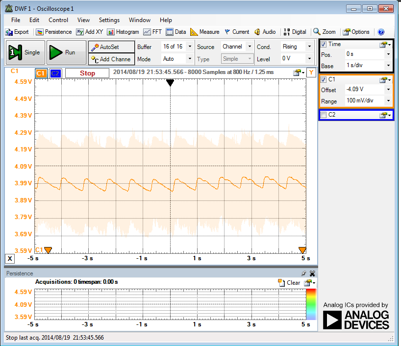
I observed the waveform of the raw pulse signal output (Vout) from fingertip on my PC using my Analog Discovery tool from Digilent. The pulse signal waveform has amplitude of a few millivolts as shown below. This waveform was generated by wearing the sensor on my index finger.
![]()
-
Sensor selection
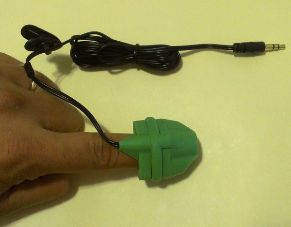
08/20/2014 at 02:16 • 0 commentsI am going to use the HRM-2511E fingertip pulse sensor manufactured by Kyoto Electronic Co., China in the prototype of this project. I have worked with this sensor before and I have found it very easy to use, and provides stable output. The HRM-2511E sensor body is built with flexible Silicone rubber material that fits nicely on the top of a finger. Inside the sensor case, an IR LED and a photodetector are placed on two opposite sides and are facing each other. The necessary connections to the LED and photodiode pins are available through a 3.5mm stereo audio connector.
![]()
HRM-2511E pulse sensor
Heart rate monitoring system
An open-source heart rate monitoring system based on the photoplethysmography principle.
 Rajendra Bhatt

