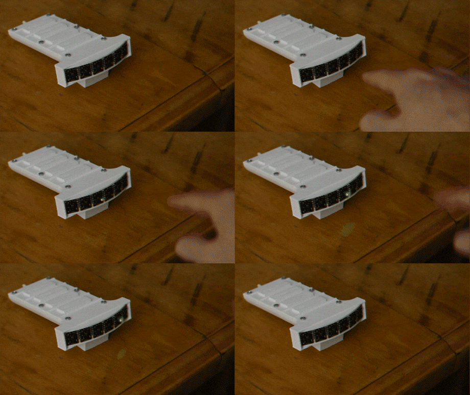
The MappyDot is part of a planned suite of enhanced sensor breakouts that offer additional measurement filtering, an easy to use I2C interface, crosstalk reduction and an automatic bus addressing scheme. This helps you integrate the sensor easily compared to its standalone counterpart, which require a complicated bus multiplexing setup, large processing overheads, a code and memory heavy API and a difficult to use I2C interface.
MappyDots provide distance measurements up to 2 meters at a non-interpolated rate up to 50Hz (or 4 meters and 100Hz for the Plus model), with a 25 degree field of view (adjustable on the Plus model). Multiple MappyDots can be chained together easily to gather multi-dimentional data about an area much like radar, without reducing sampling rate due to processing overheads. They are also calibrated out-of-the-box to within ±1mm, and can be easily re-calibrated if integrated into a commercial enclosure. The MappyDot also performs low pass filtering on the motion data that arrives from the sensor, to provide you with the clearest picture of the environment around it. While distance measurement is the name of the game, the MappyDot also offers the following features:
- Auto addressed bus scheme for chaining up to 112 devices.
- A 2.8-5V signalling and operating voltage range which will work with your platform of choice.
- A simplified I2C interface for easy integration into new or existing projects with next to zero code and processing requirements.
- Reduced device initialisation and upkeep times. Many devices can now share the same bus with the fastest possible update rates. For example, you can poll 112 MappyDots, 50 times each, every second for a total of 5600 measurements per second (depending on your host processing speed).
- Inter-sensor crosstalk reduction and measurement synchronisation to reduce measurement errors.
- Low pass, real-time filtering to reduce background noise effects.
- Automatic mode switching to get optimal measurements depending on the environment.
- More advanced features and device pass-through for complex applications.
- In-service firmware upgradability via I2C. There’s no need to disconnect already deployed and integrated devices.
- Open source sensor firmware.
- Threshold controlled, PWM or interrupt output from an onboard GPIO pin for standalone or distributed applications.
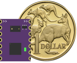
- A tiny footprint - 13x17.8mm (0.51x0.70").
- An easy to solder standard 2.54mm (0.1") pinout that can be used for either soldering directly to production boards or to header pins or wires for prototyping and breadboarding.
- A user controllable LED (PWM, threshold, measurement or manual modes).
- Device naming for easy recognition.
- Precalibration for plug and play use, as well as auto user calibration.
All this is possible, without the need for any additional processing on your platform of choice.
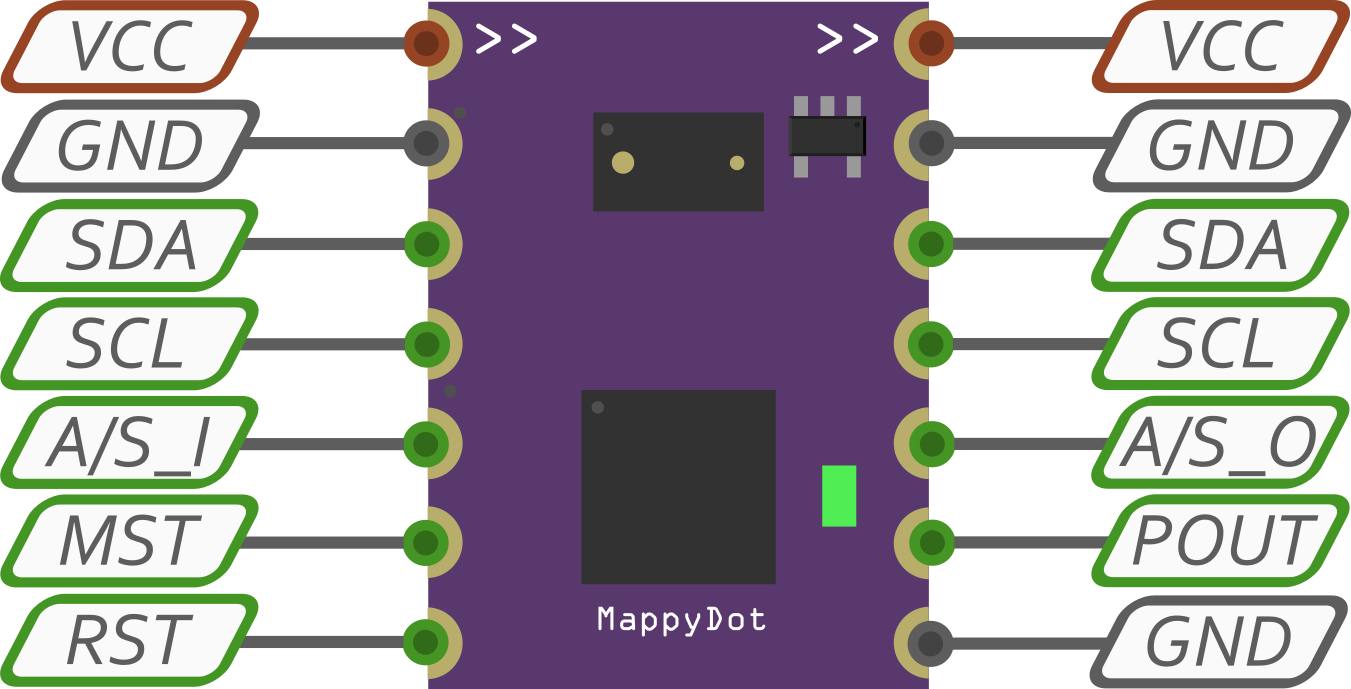 When the devices are connected to a power source (2.8-5.5V), they automatically initialise with an array of addresses, which can be easily scanned and polled to determine what is on their I2C bus from a controller. From there the devices can be read with a few lines of code.
Upon first power up, the MappyDot allows users to obtain an accurate 16bit position with two lines of Arduino code:
  Wire.requestFrom(address, 2);
  distance = Wire.read() << 8; distance |= Wire.read();
It's that simple, there's nothing else to it. No special libraries to load, just read a value from the I2C lines.
The default MappyDot firmware offers different operating modes from the MappyDot Standard mode:
- Highly Accurate - 1.2m - 5Hz
- Long Range - 2m - 30Hz
- High Speed - 1.2m - 50Hz
- VL53L0X Default - 1.2m - 30Hz
- MappyDot Standard - 2m auto switching - 50Hz
However, you can always tweak and update the firmware as you please via the I2C bootloader.
All MappyDot code, documentation and design on these project pages are licensed under the GNU General Public License (GPL) unless otherwise stated.
 Blecky
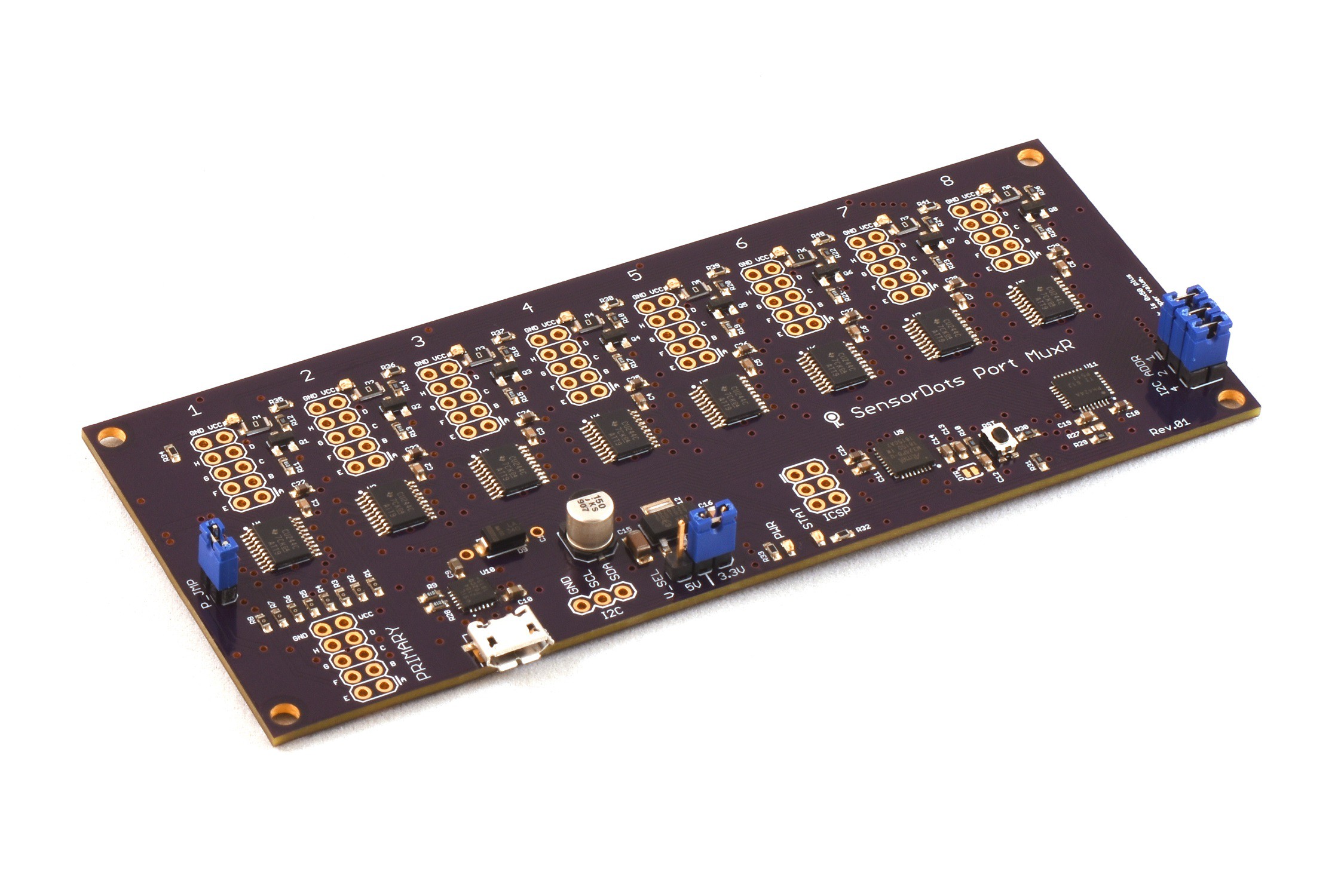
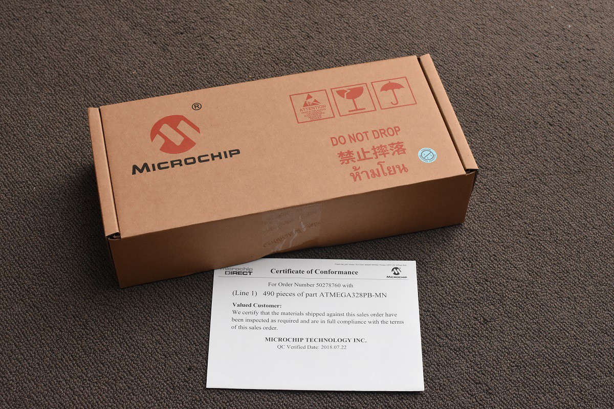
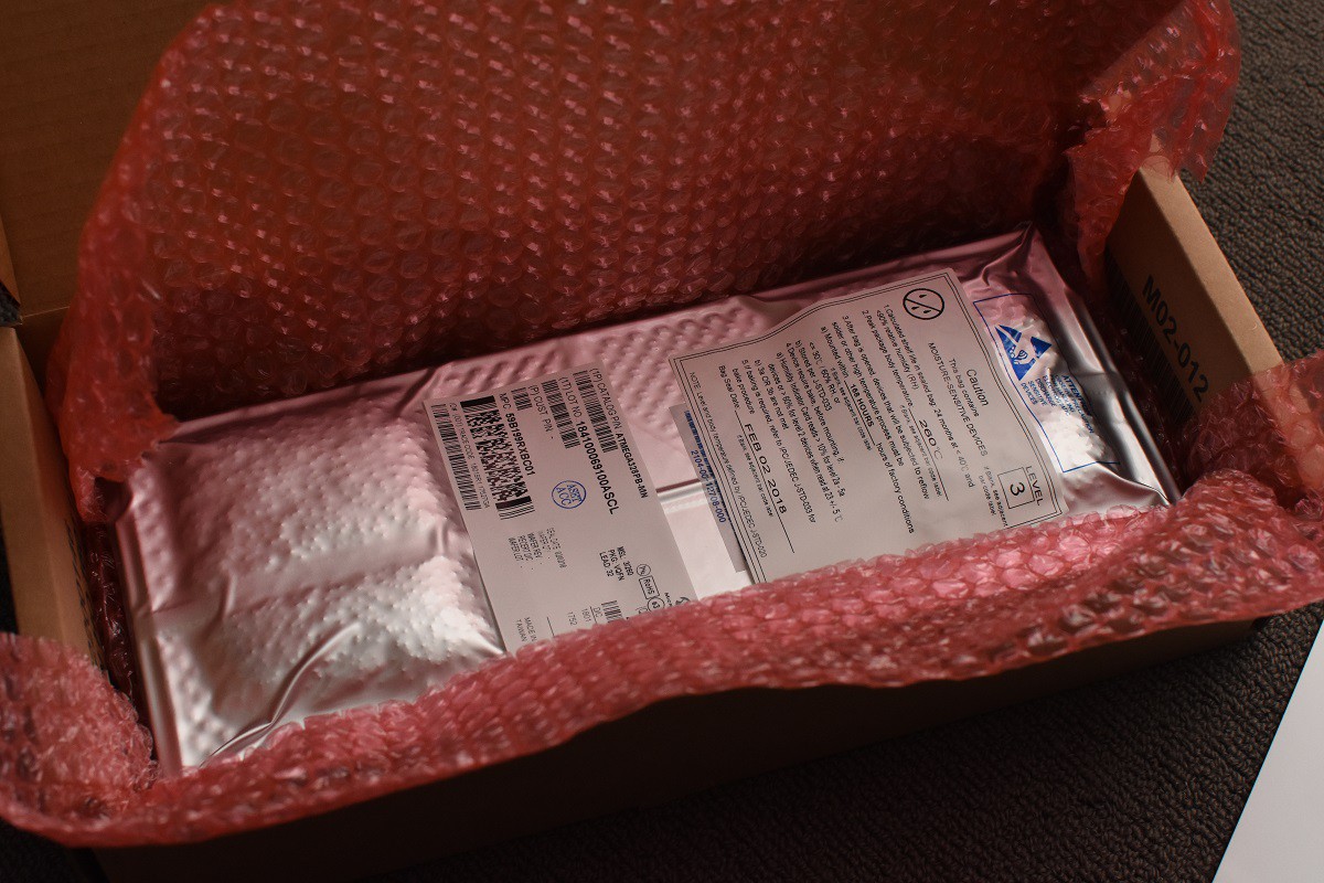
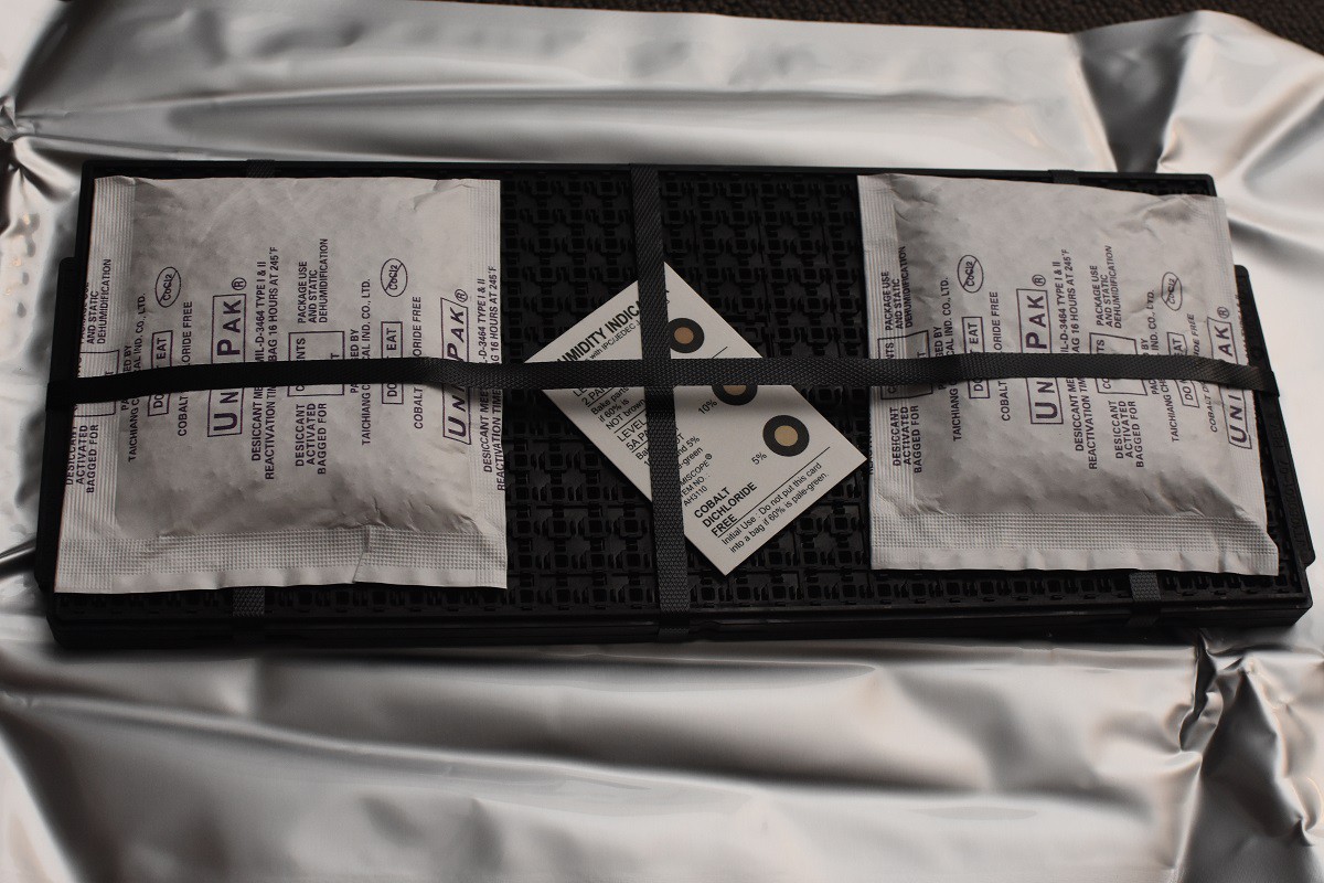 And here are the microcontrollers on the tray:
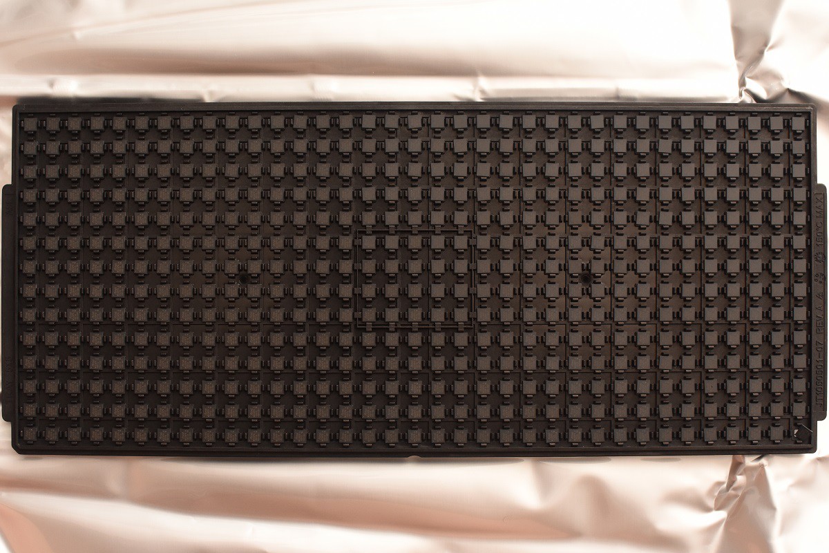
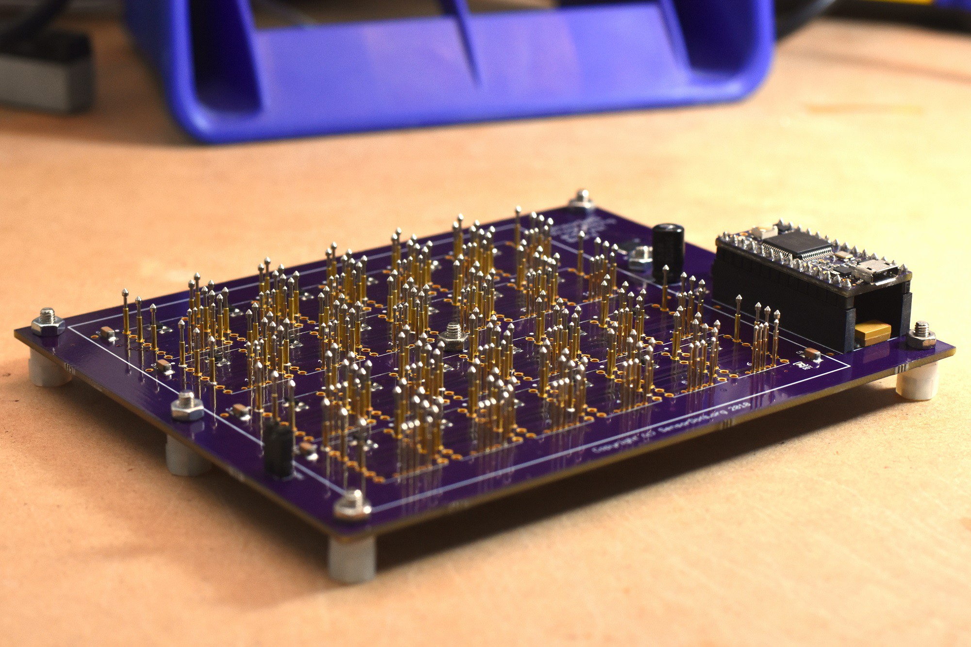
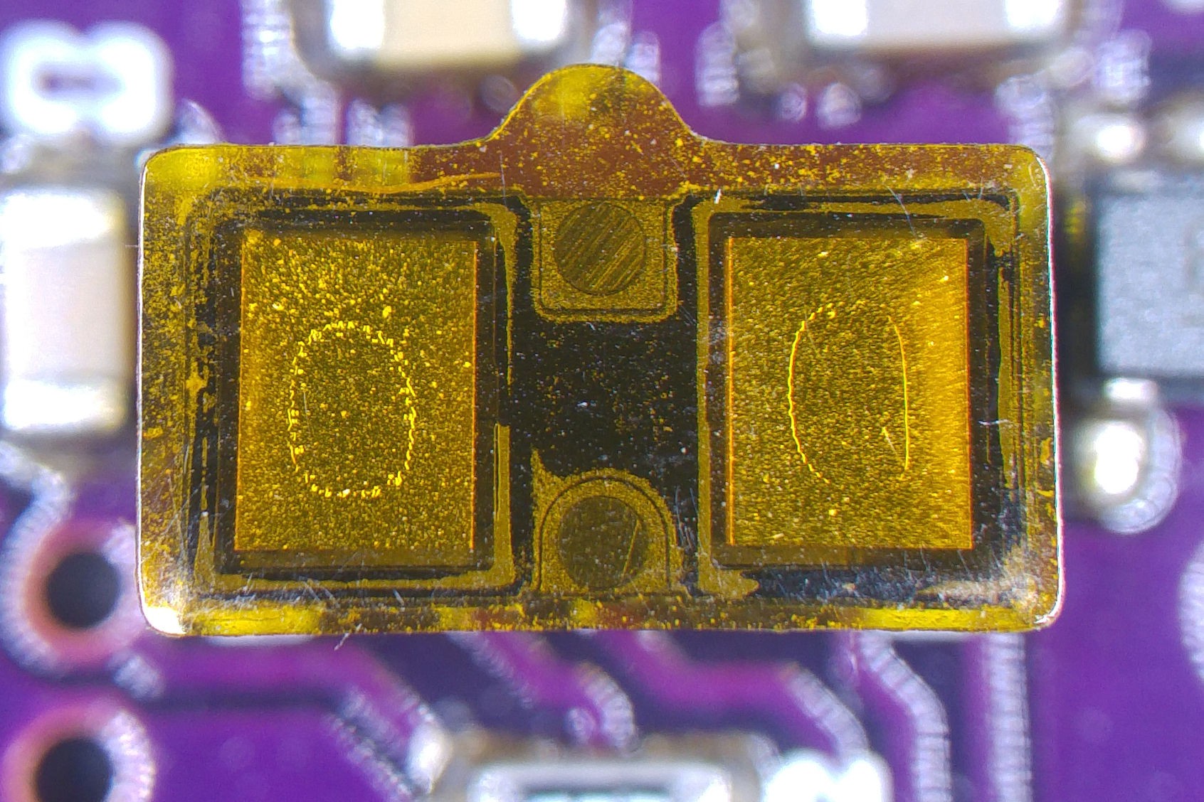
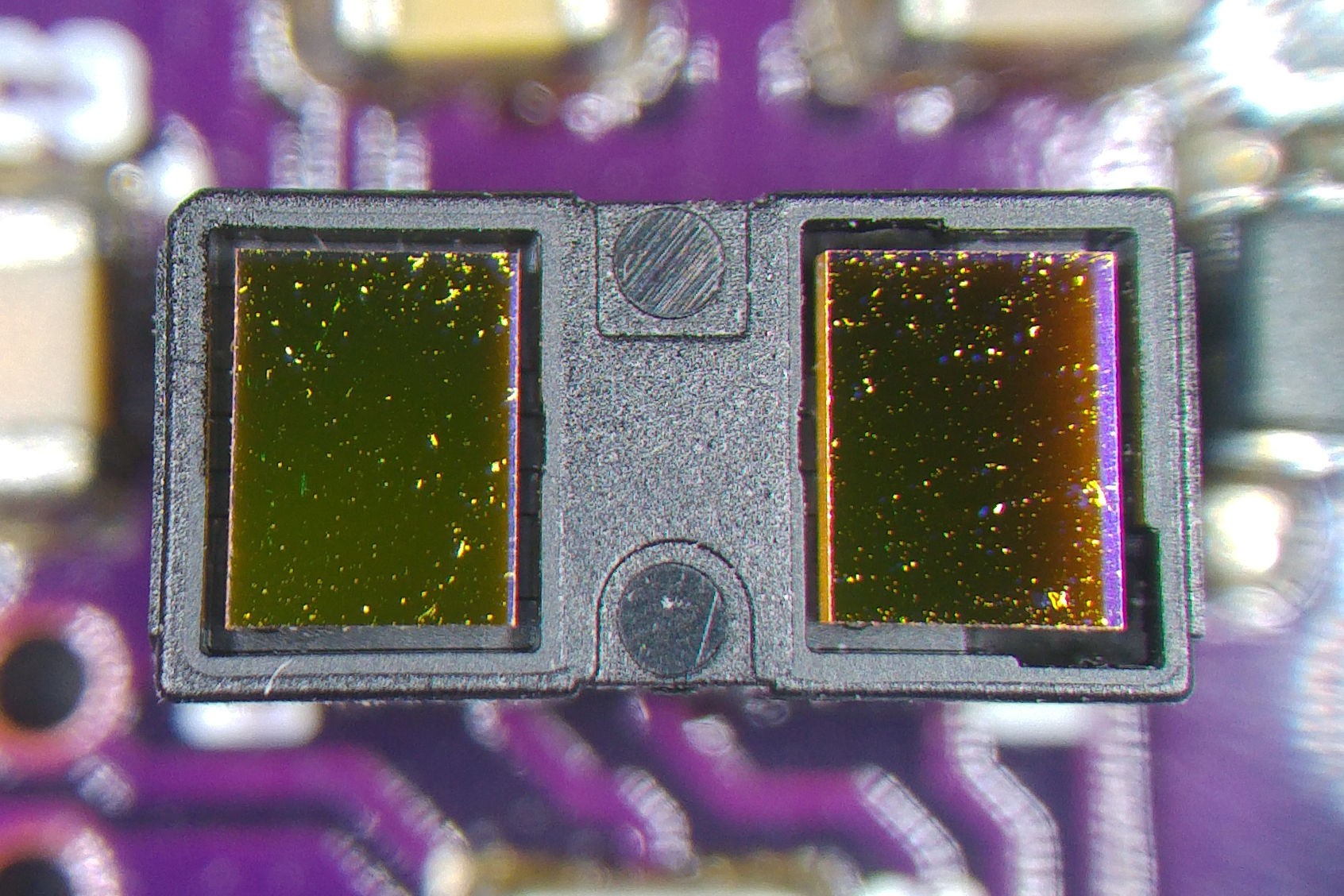
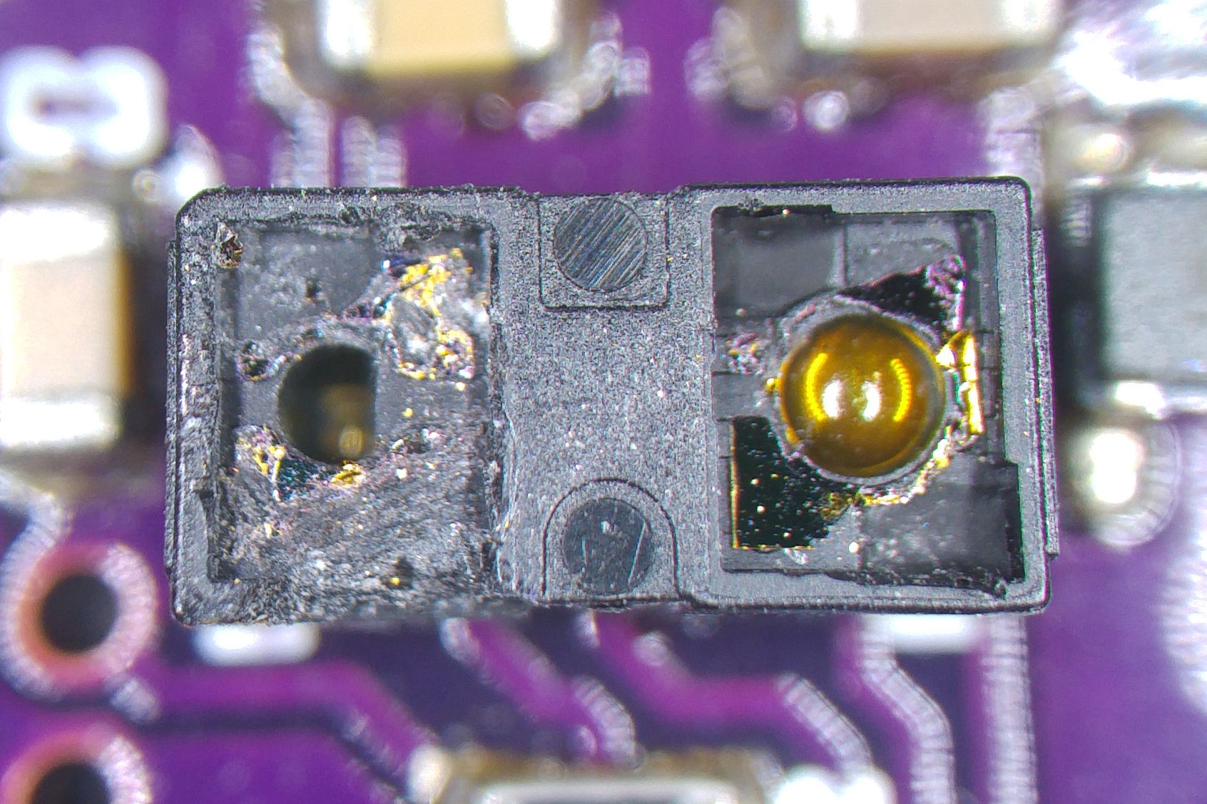
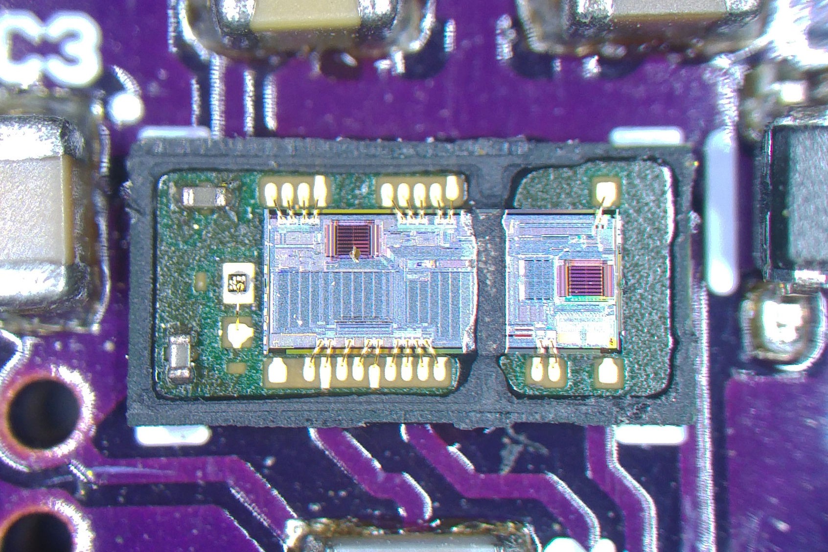
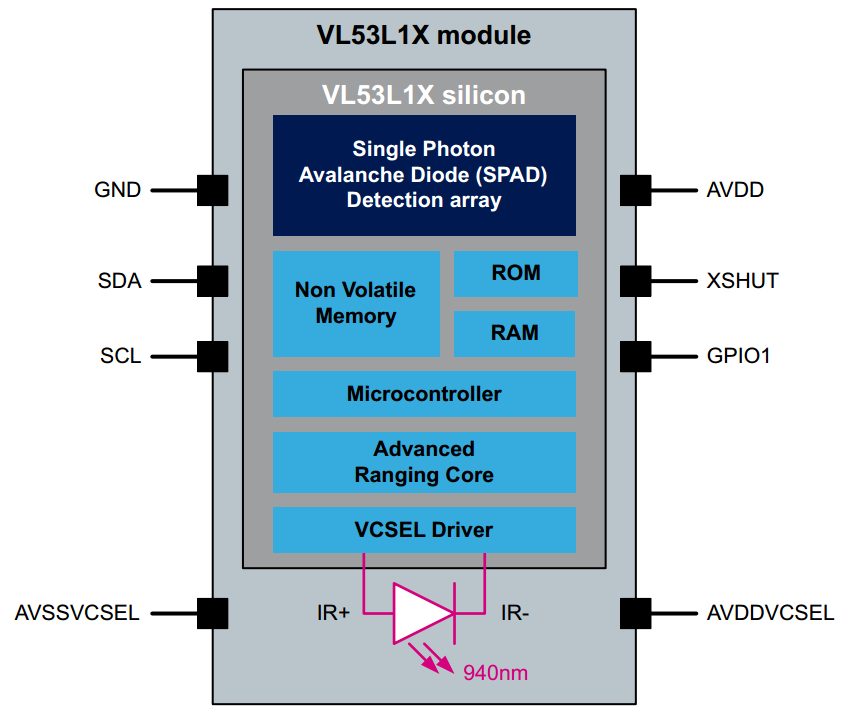
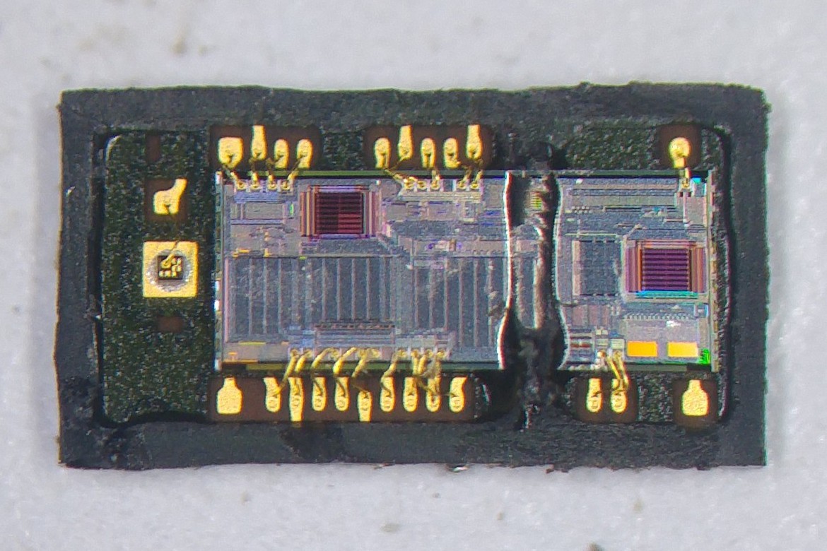 Now it makes sense that the footprint on the VL53L1X is identical to the VL53L0X.






 Tim Wilkinson
 Alastair Young
U stated the various settings, inc Hi accuracy... how hi?