Blecky
-
The Importance of Stencils
07/09/2017 at 08:44 • 2 commentsSo I had a bit of spare time today and decided to go about soldering a MappyDot by "hand".
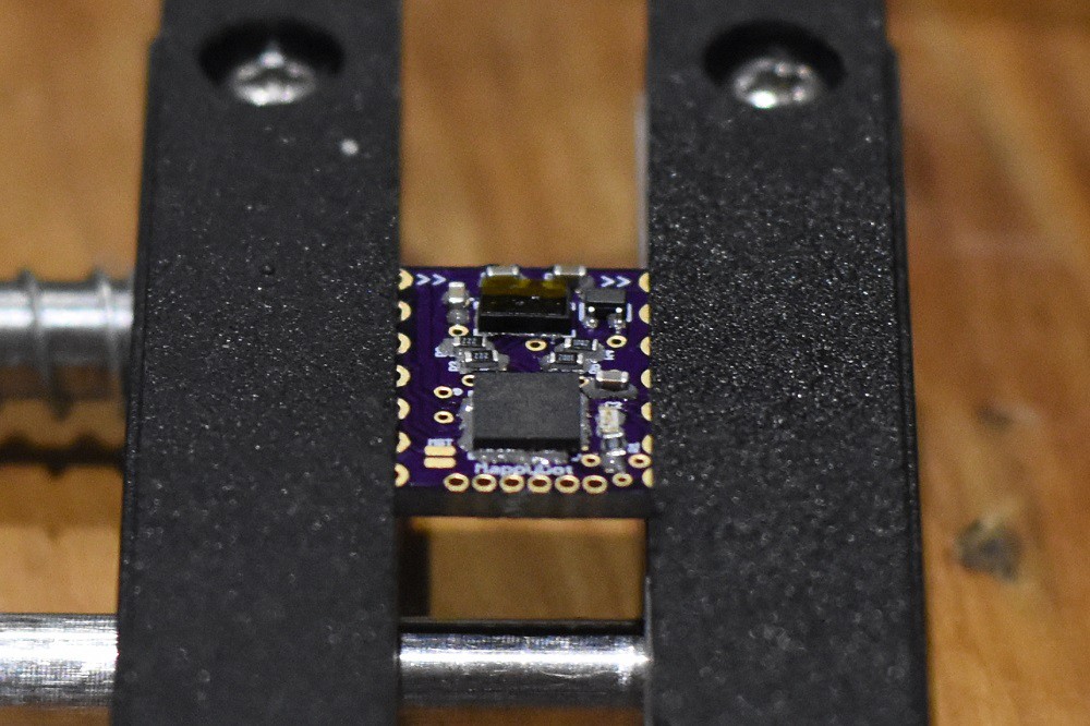
Just bung on a bit of solder paste, place the components:
![]()
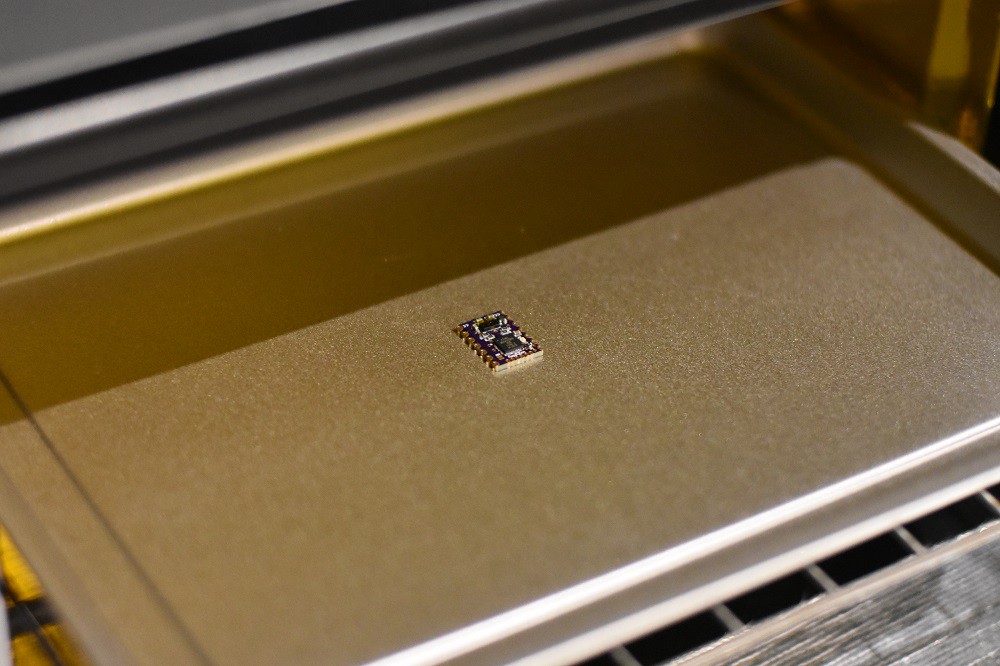
Place in the reflow oven:
![]()
Fire that sucker:
![]()
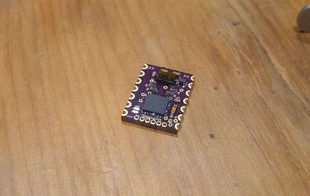
Bish bash bosh:
![]()
Oh wait....
Well that didn't go too well. A couple of components have jumped pads (bottom right) and the VQFN is bridged. A bit of hand soldering and a microscope will fix this no problems, but that's a pain.
The reason all this doesn't go to plan so easily is that excess solder will flow and displace everywhere when it has nowhere to go, causing solder bridges and components to move.
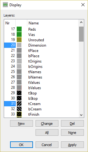
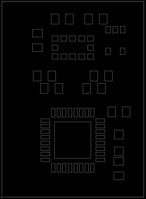
So in comes the solder stencil to get the right amount of solder per pad. In Eagle you can export a solder stencil to a laser cutter by editing the document to show only the dimension and cream layers:
![]()
Then change the tCream layer's fill style:
![]()
Since this is a single sided board, we just show the tCream layer, which will net (hehe) something like this:
![]()
You can then print this straight to a laser cutter, or export to DXF which can be used to cut with. Unfortunately this will have to wait until later in the week as I don't have the wife approval to splurge on a laser cutter. In the meantime, I will fix this board up under the scope and get it running.
-
PCB Delivery
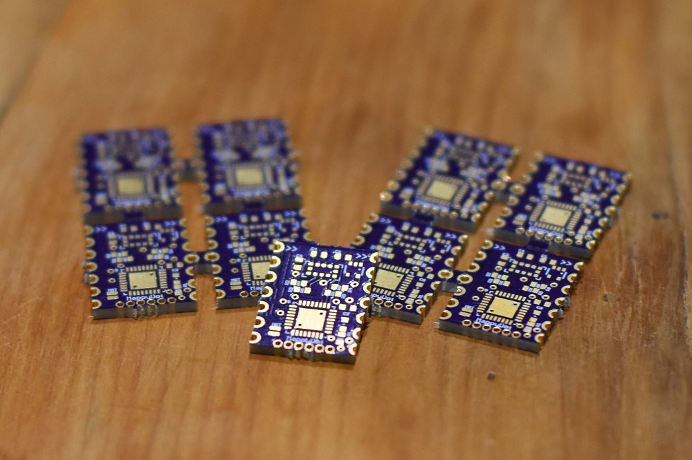
07/04/2017 at 12:20 • 3 commentsThe PCBs have arrived from OSHPark! They are so tiny.
![]()
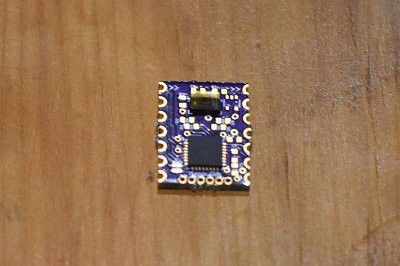
And a test fit:
![]()
The through hole coating on the cut side pins seems decent enough, however I will have to test the strength of it to see if it holds up. It looks to have bonded well enough however.
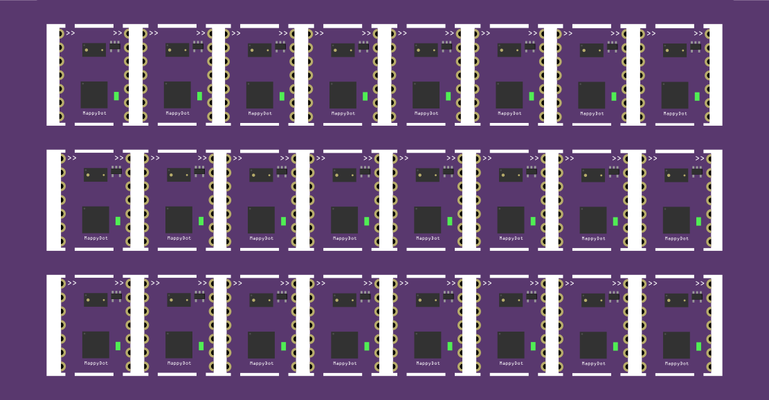
The plan is to panelise these boards in such a configuration so prevent damage to the pins:
![]()
-
Parts Delivery
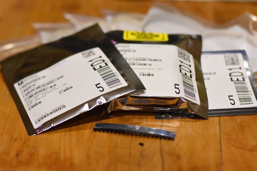
06/28/2017 at 11:03 • 0 commentsThe parts for the first batch of prototypes arrived:
![]()
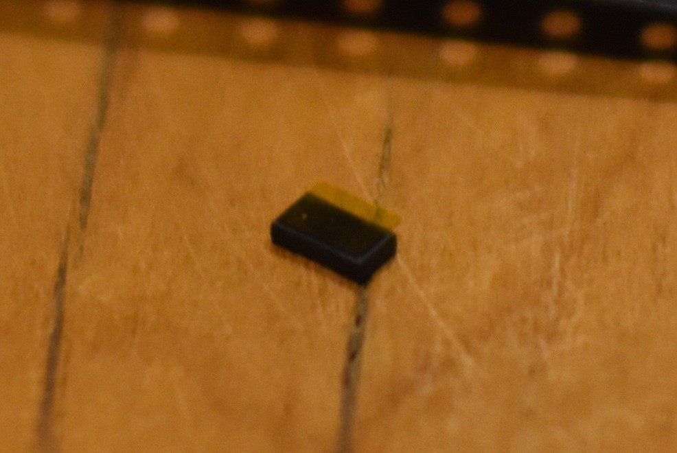
The ST VL53L0X is tiny tiny tiny:
![]() Enhance:
Enhance:![]()
-
How is the MappyDot Different to a Breakout Board?
06/24/2017 at 14:38 • 2 commentsThe MappyDot is based on the ST VL53L0X and provides an i2c interface for access to each device. So you might be asking why wouldn't you just use something like the Adafruit VL53L0X breakout board?
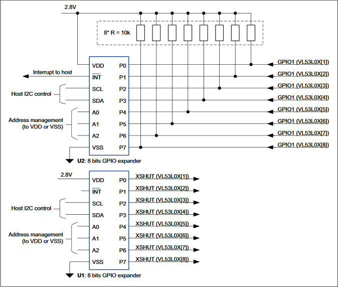
Well the MappyDot is more than just the VL53L0X sensor on a board. For starters, the VL53L0X itself is a 1D measurement, i2c device with a single fixed address. So you would need multiple i2c transceivers on your microcontroller to run more than one VL53L0X sensor for full spherical environment measurement or building an air piano. Alternatively you could use an i2c bus multiplexer or follow ST's app note, but this requires additional addressing pins or separate i2c control commands. However, multiplexing adds a lot of complexity to designs, only operate up to 8 devices each, makes it difficult to integrate into a long bus, and it also adds undesirable device switching and control/measurement delays.
![]()
ST's App Note for connecting multiple VL53L0X sensors.
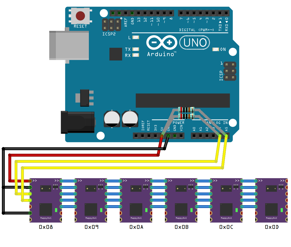
The MappyDot overcomes this by using onboard logic that auto-configures a different i2c address for each device in a chain, which makes them accessible from a single i2c master. This allows you to address up to 112 devices on a single bus:
![]()
MappyDots easily enable multiple devices in a chain with unique addressing. MappyDots also enable constant measurement and (optional) averaging functions which reduces distance setup and read latency, while increasing accuracy and measurement speeds at no additional processing cost.
Each MappyDot is easy to set up. There's no special libraries to import or functions to program, all you need to do is perform an i2c read on the address/device you require and it will give you the distance measurement instantly as a two byte value. This is perfect for integration with existing robotics or autopilot hardware with minimal fuss or program storage requirements. The default operating mode also switches automatically to the optimal parameters required for different environments.
If you require more advanced configuration options, the MappyDot also gives you access to all the low level operating modes and control for the VL53L0X sensor. So it's great for more advanced applications.
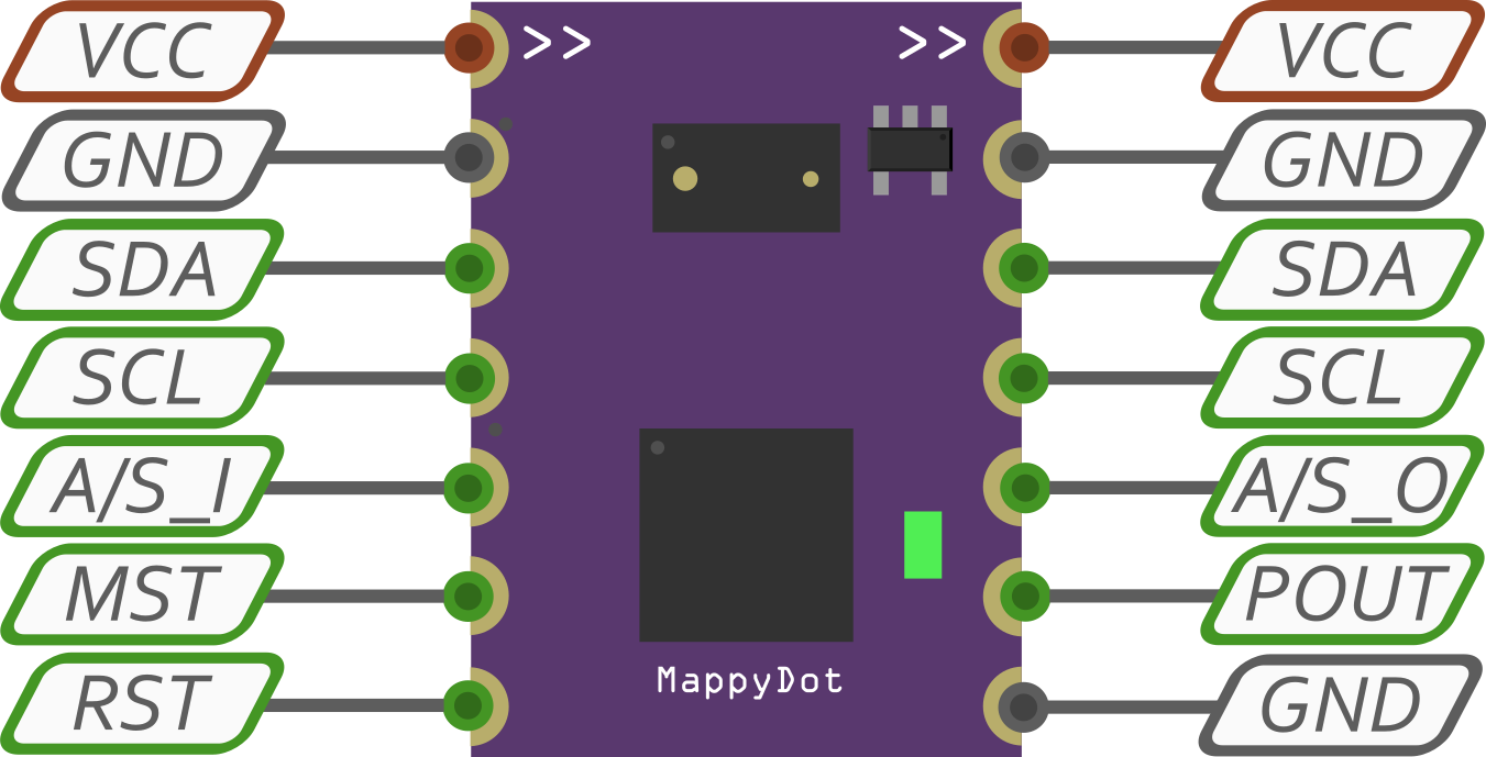
The MappyDot is a tiny module only 12.70x17.48 mm (0.50x0.69 inches) in size. It provides standard 2.54mm (0.100") header locations which can accommodate either pin headers or SMD soldering for integration into new or existing hardware designs. MappyDots operate between 2.8 and 5.5V, so there's no need to worry about whether it will work with your platform of choice.
![]()
There's also an onboard LED which can be configured to light up when certain threshold values are reached, when the MappyDot is read for sci-fi cred, or manually controlled to identify each sensor.