 Dennis
-
1Starting the build
It’s always nice to receive a Digi-Key box. It means more toys. Also, the first parts for the new build.
![]()
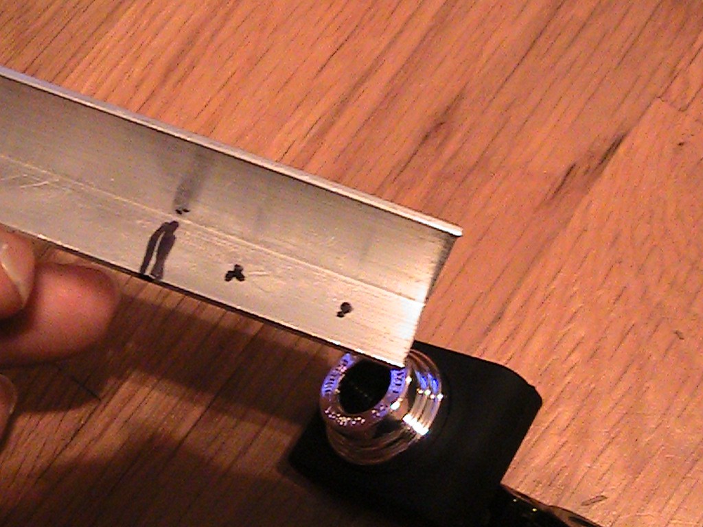
I’m using an aluminum L bar to make the camera mount. This one is a 1/2” x ¾’. I measured and mark a 1 ½” length and also mark the mounting holes around ¼” from each side. Drill 1/8” mounting holes and cut the 1 ½” length. I like to file off any burrs and round the edges.
![]()
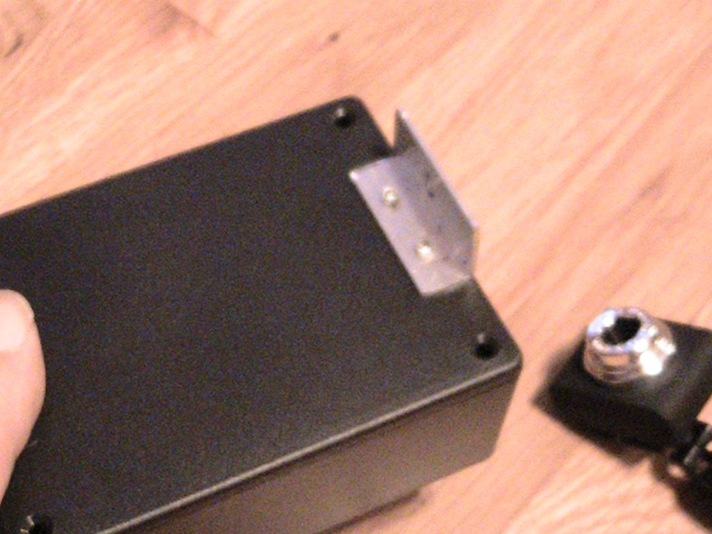
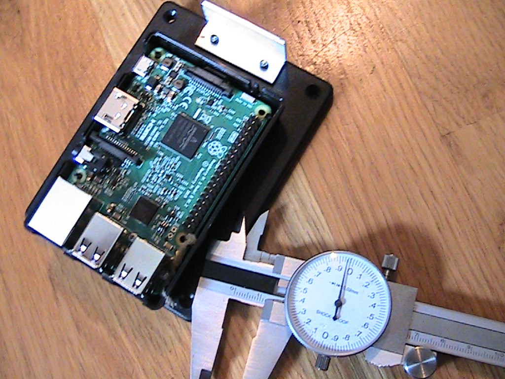
Next, center the aluminum mount on one side of the top of the box and drill the 1/8” holes. I pop riveted the mount on the cover, but machine screws will work also. The low definition USB camera should clip easily on the mount![]()
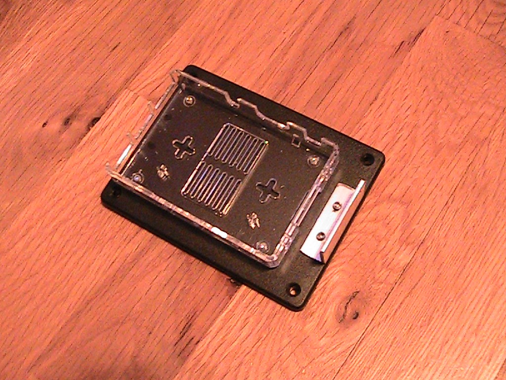
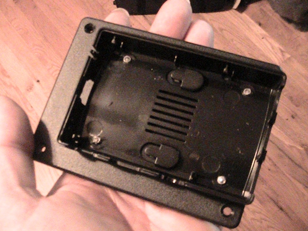
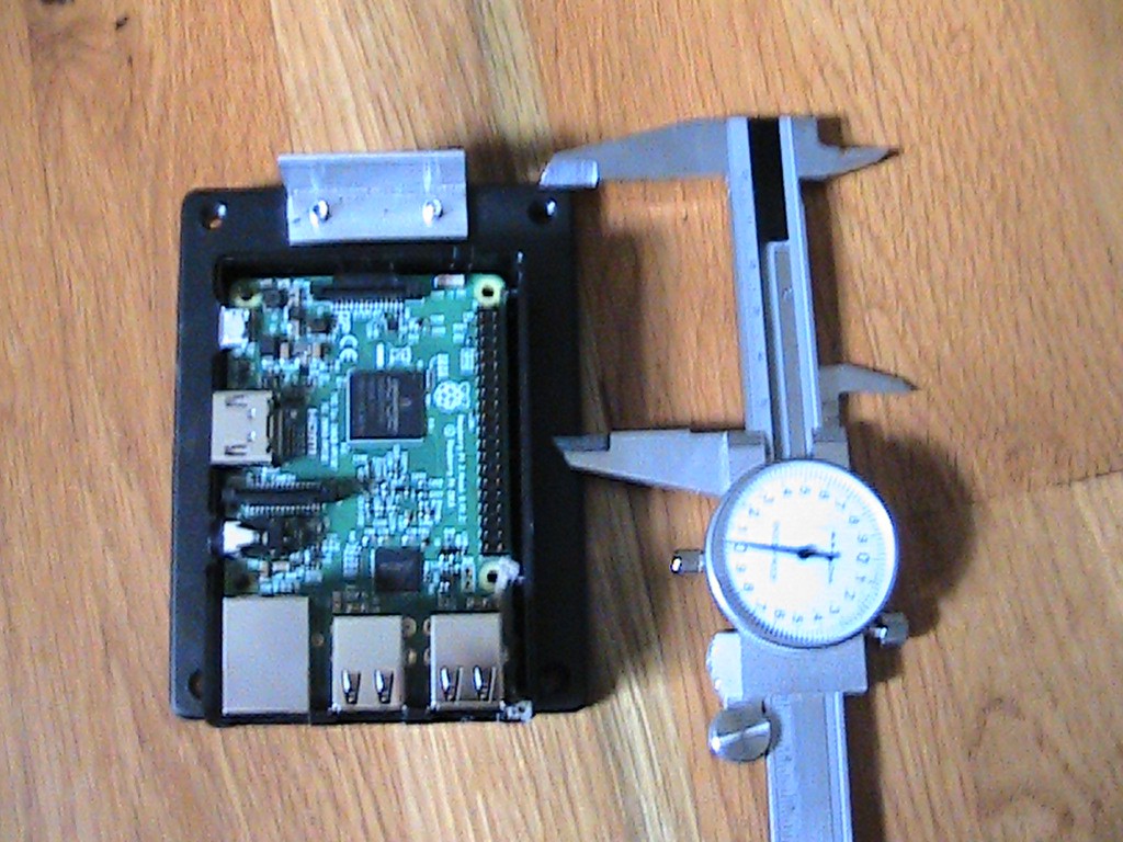
Next, take the bottom of a Raspberry Pi case and drill four 1/8" holes on the feet.
Place the bottom of the case on top of the box centered behind the camera mount and drill 4 small holes. I used 4 1/8" pop rivets to secure the Raspberry PI case to the box.
![]()
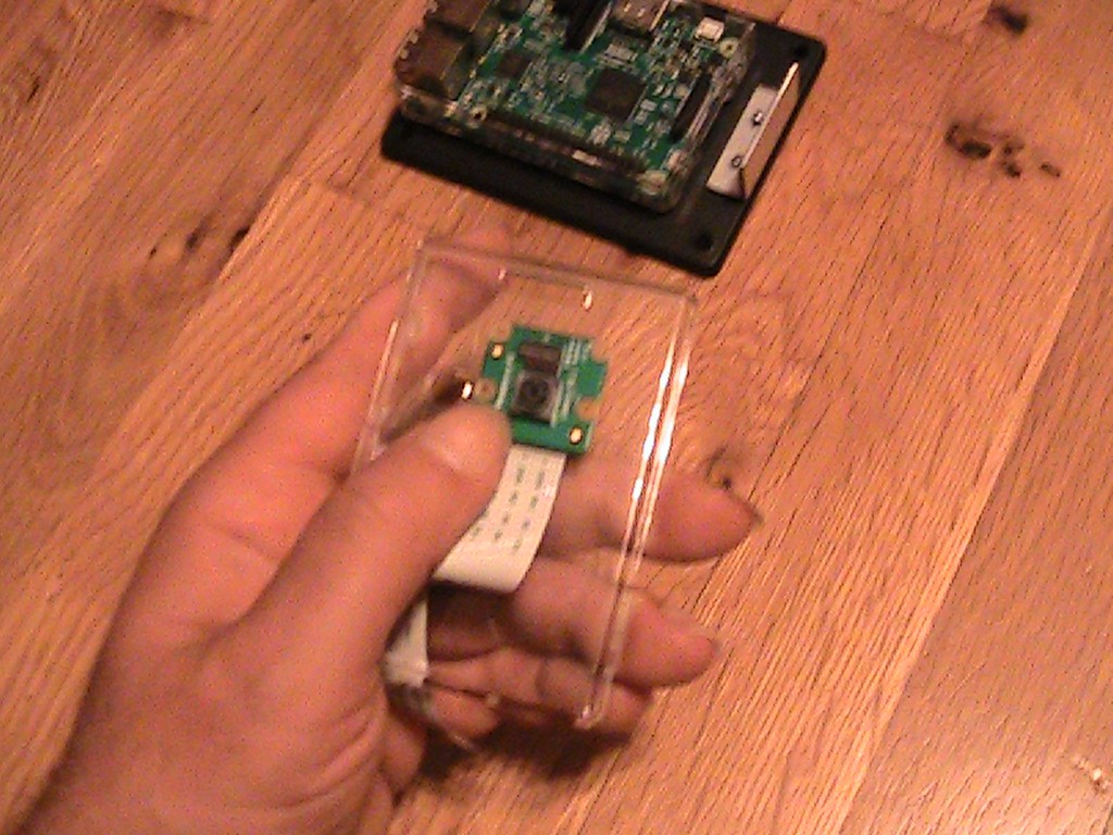
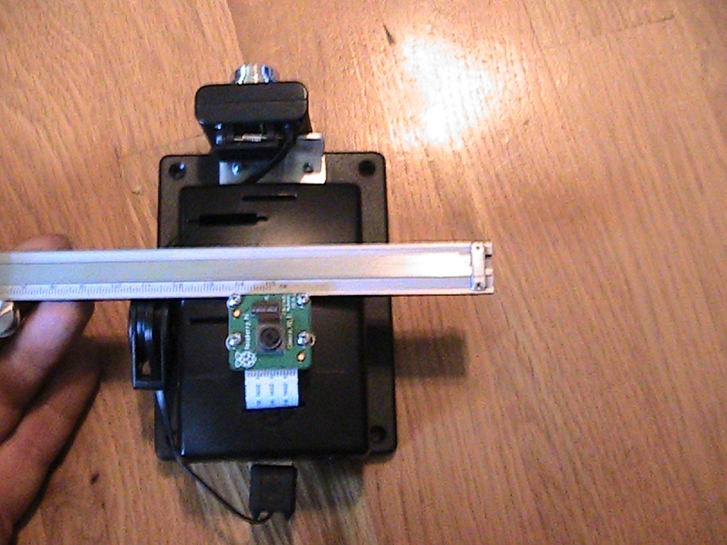
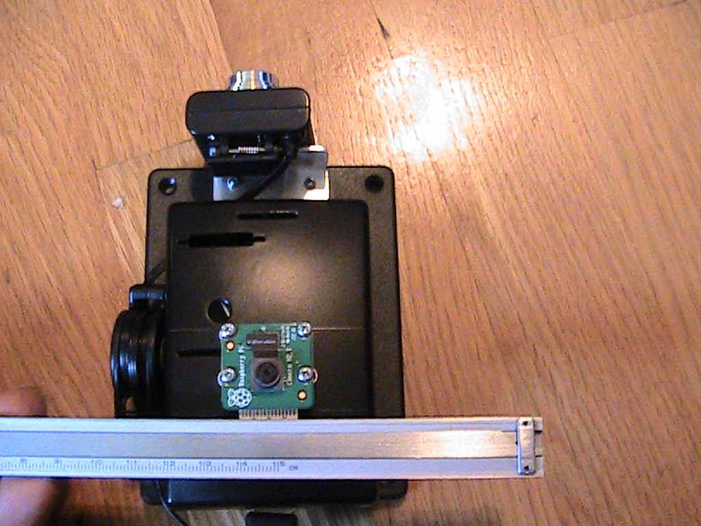
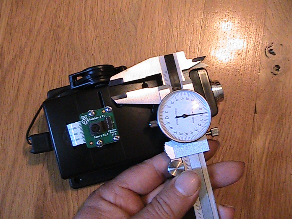
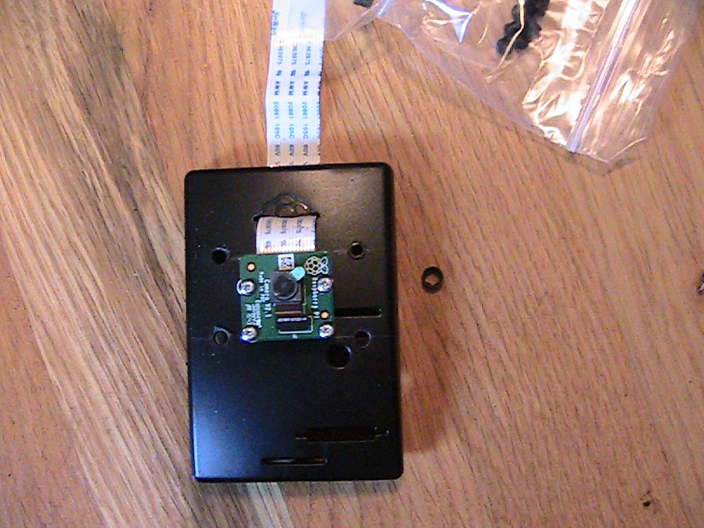
On the top of the Raspberry PI case, I positioned the Raspberry PI camera and drilled 4 small holes to mount the Raspberry PI camera.
![]()
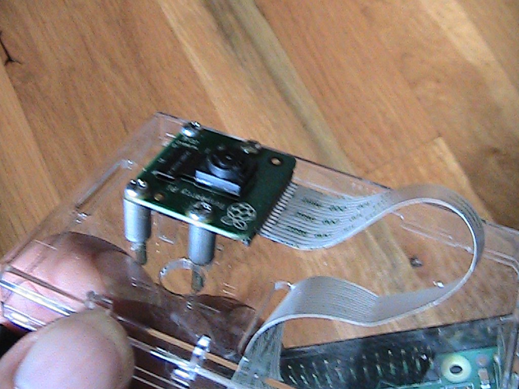
With 4 screws and four ½” stand offs, I connected the cameras to the top of the Raspberry PI case.
![]()
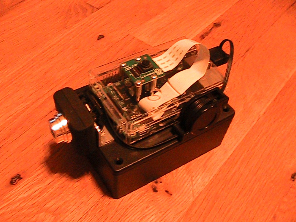
Next, plug everything in and snap together the parts and the top of the bot is assembled. I haven’t gotten the gearhead motors yet, but hopefully soon.
![]()
-
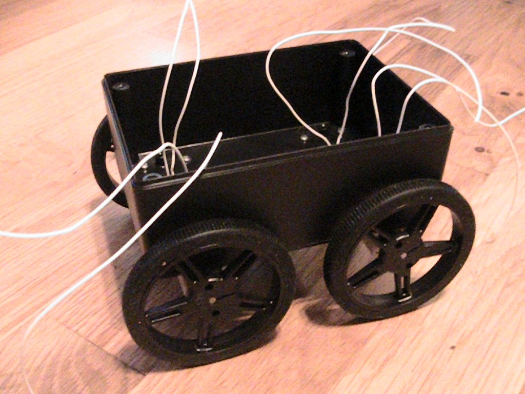
2Mounting the wheels and gearhead motors.
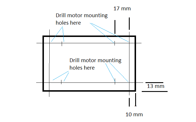
Below is a diagram showing the measurements I came up with for mounting the gearhead motors. The blue lines point to where the mounting holes need to be drilled.
![]()
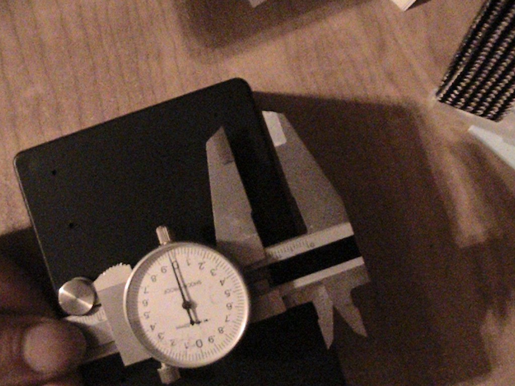
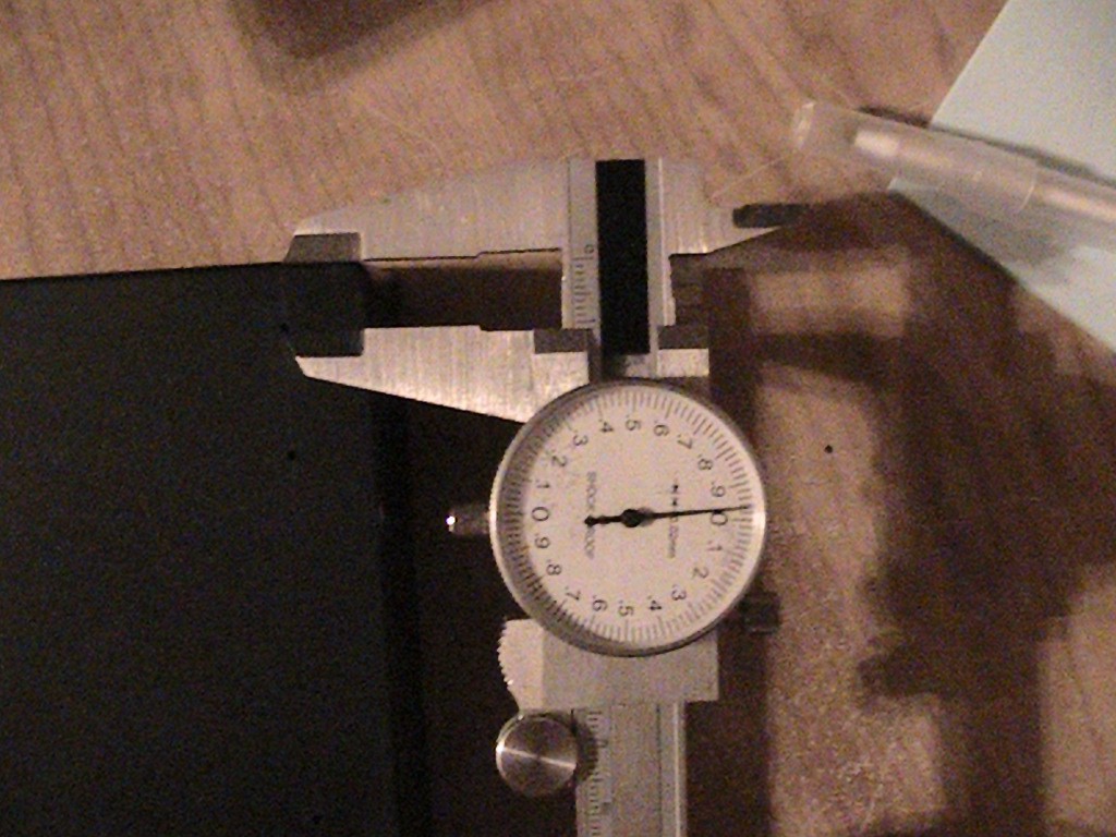
With a set of calipers, I scratched a line 13 mm from each side and also a line 10 mm from the front of the box and also 10 mm from the back of the box.
![]()
![]()
Then, I measured 17 mm from the location where the 4 lines cross towards the inside of the box and drilled 0.086” mounting holes. The mounting brackets come with #2-56×7/16" screws.
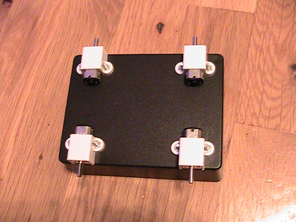
I then placed the gearhead motors in the mounting brackets and bolted them to the box.
![]()
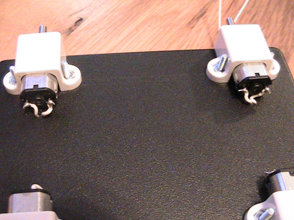
Then, I soldered wires to each motor, drilled holes near the base of each motor and carefully routed the wires into the box.
![]()
After that, I placed a drop of glue inside of the center hole of each wheel and pressed them on the motor shafts. Be careful not to glue the motor shaft to the motor
![]()
And that completes the motor and wheel mounting.
-
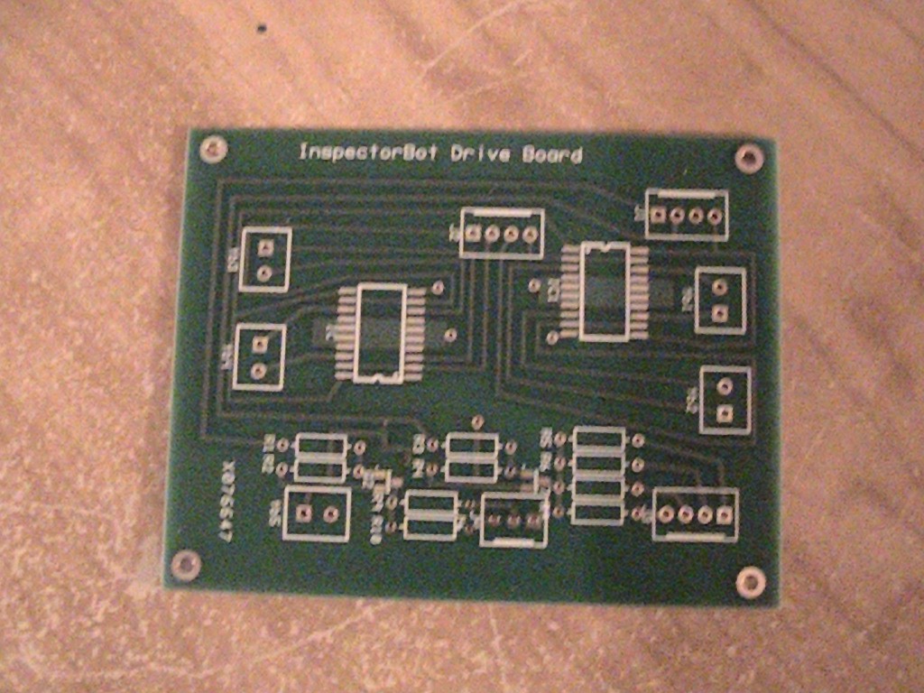
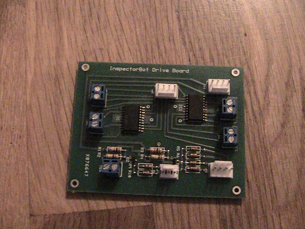
3Solder the components on the motor drive board.
I got the new drive motor boards, so it’s time to solder the components on. There are only 4 surface mount components to solder, 2 dual h-bridges and 2 transistors. The rest of the parts resistors and connectors are all through hole. The boards are fairly easy to populate.
![]()
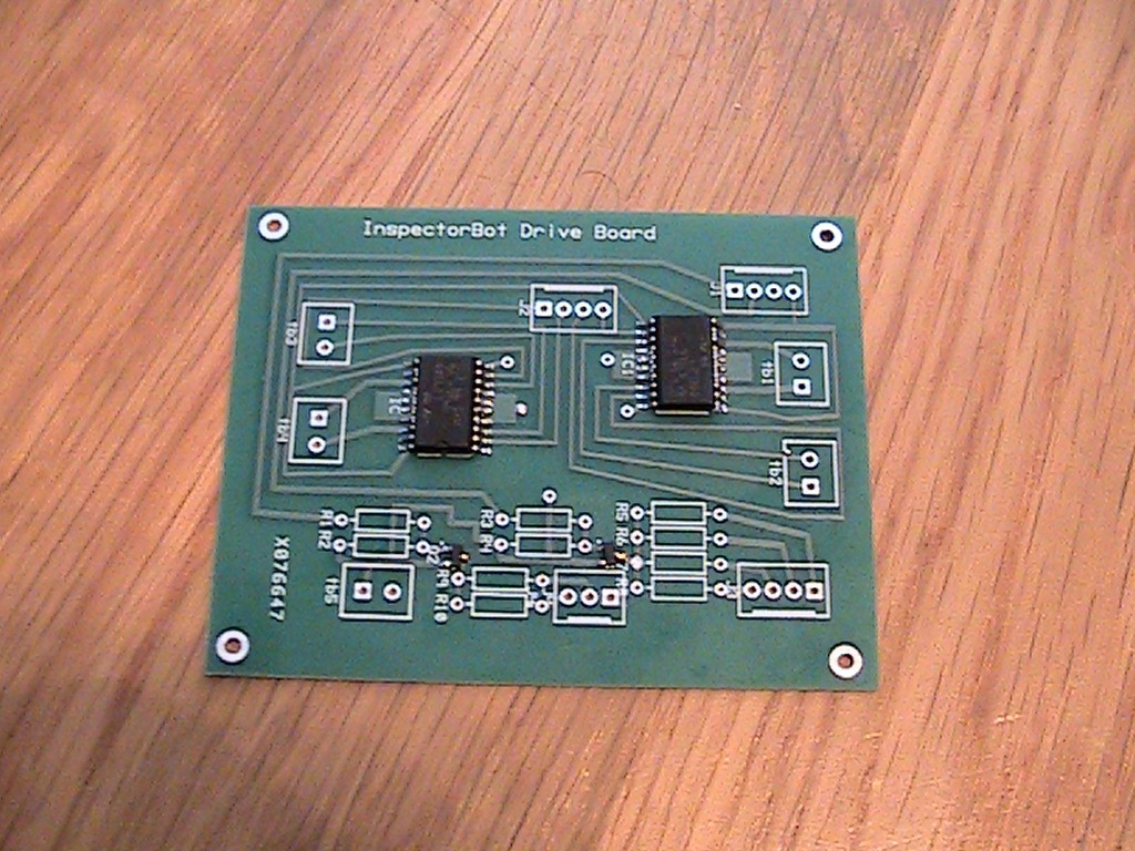
I always solder the surface mount components on first. The transistors can be a little tricky. Make sure pin 1 on the h-bridge chips are in the right place. It is always frustrating to solder a chip on a board and latter find out the chip is soldered on backward. :(
![]()
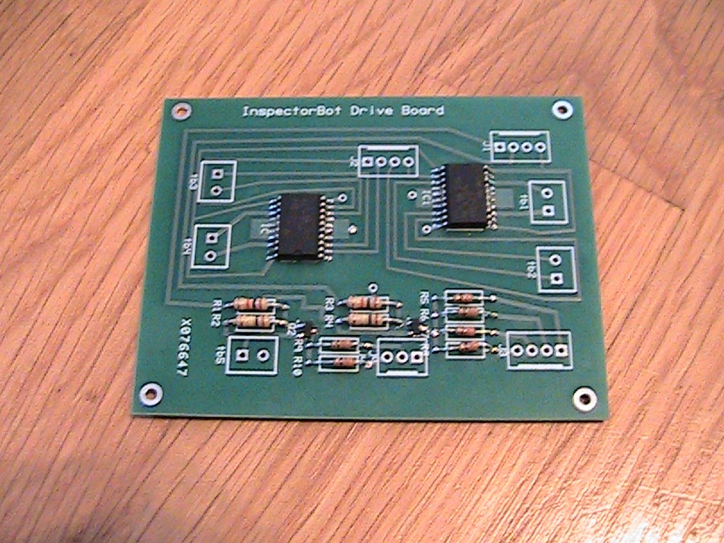
Next solder on the resistors.
![]()
And last all of the connectors.
![]()
The finished motor drive board. Not too difficult.
-
4Adding the board and upward pointing LEDs to the build.
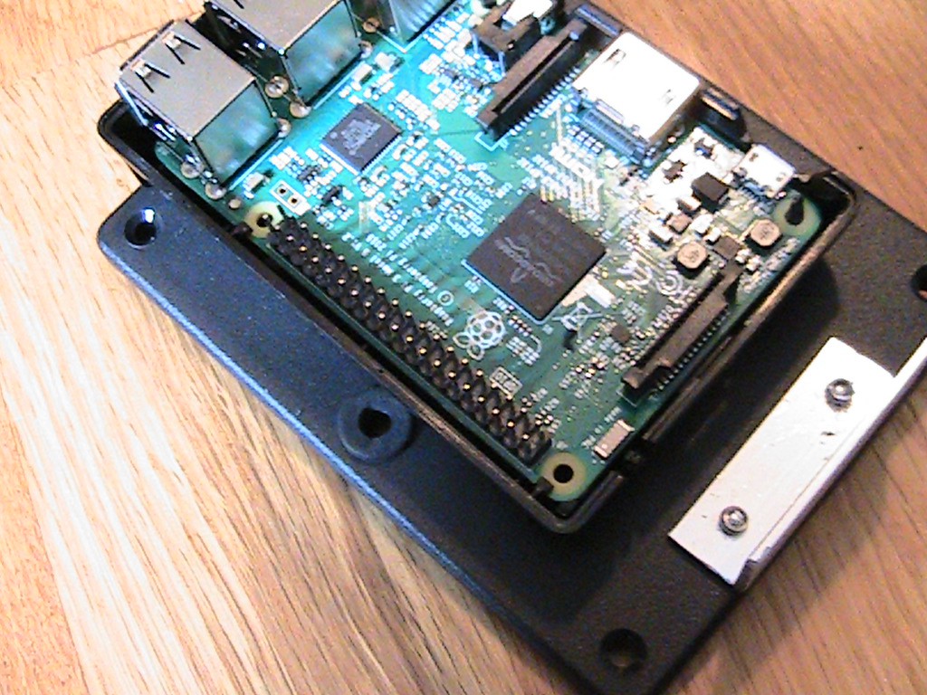
This is InspectorBot sporting its new black Pi case. First, we will need some holes to mount the LED holders and route the wires from the PI to the drive board.
![]()
First, on the top of the Pi case, mark 2 lines across the top cover using the camera as a reference.
![]()
![]()
Then, measure and mark a line 1 cm from the sides on the lines we just made.
![]()
Drill four 5.7 cm holes on the marks.
![]()
Next, we need a hole to route the wires from the Pi to the drive board. On the right side of the box cover beside the bottom of the Pi case, measure and mark a line 5.5 cm from the front of the box cover.
![]()
Next, measure and mark a line 12 mm from the side.
![]()
Drill a ¼” hole and insert a grommet.
![]()
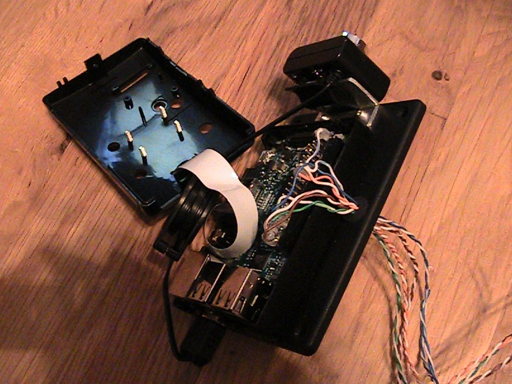
Route eight wires through the holes. I’m using 24 gauge solid wires and cutting longer than needed lengths so they can be cut to size and soldered in place. Solder one end of the wires on a header plugged into the PI. I also hot glued the connections to add a little protection. I left the unused pins not glued to allow future expanding.
![]()
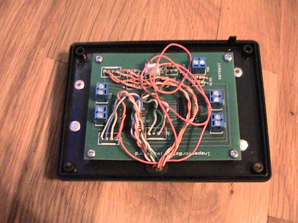
Solder the wires to the drive board. I took the connectors off to get a little more room.
![]()
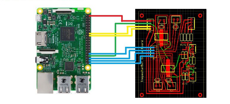
Below is a wiring diagram to show the connections.
![]()
-
5Finish the mechanical build.
Insert five additional wires through the grommet on the top cover of the box. I cut over-sized wires so I can cut them to size later. The colors do not matter, but I like to have one red wire for the positive connection. On the top cover of the Raspberry PI case, insert the LED with holders in the four 5.7mm holes. Connect all of the anodes together and solder the red power wire to the anode connections. Solder a wire to each of the four cathode connections on the LEDs.
![]()
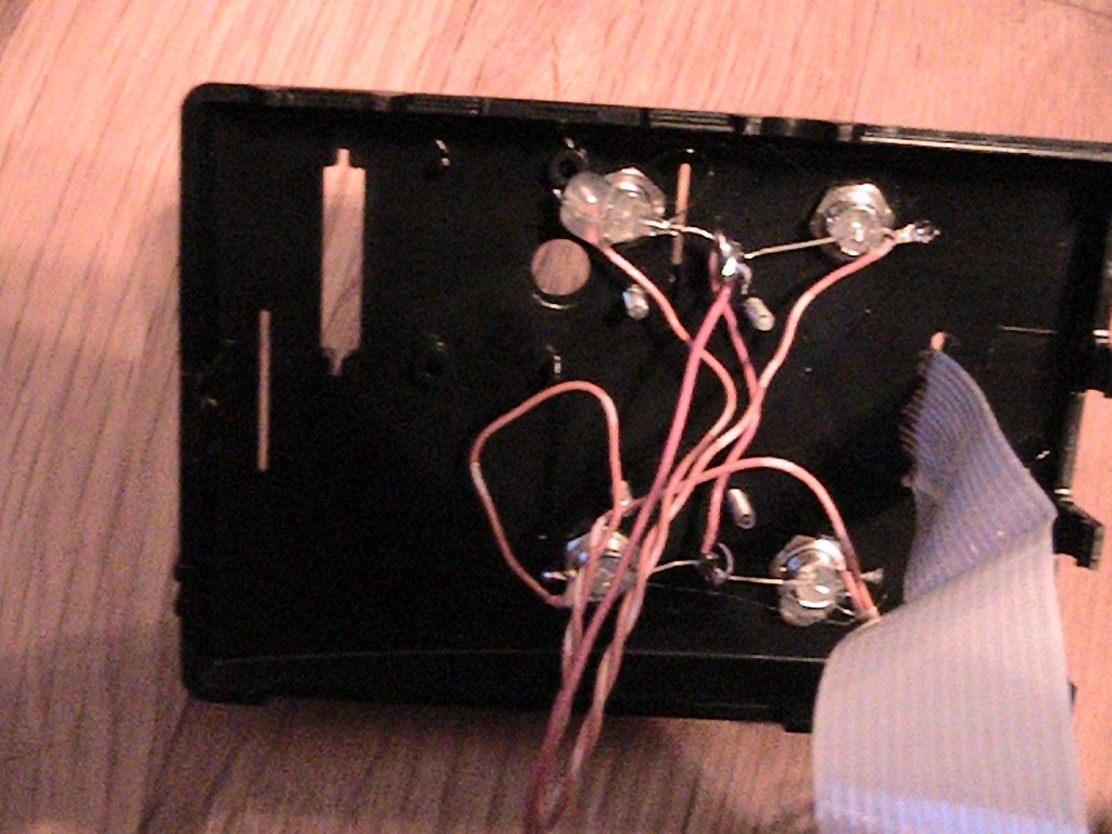
On the bottom side of the box top, solder the four cathode wires to “J3”. It does not matter which wire goes to which pin. Leave the red anode wire loose for now.
Bottom battery plate and charging port:
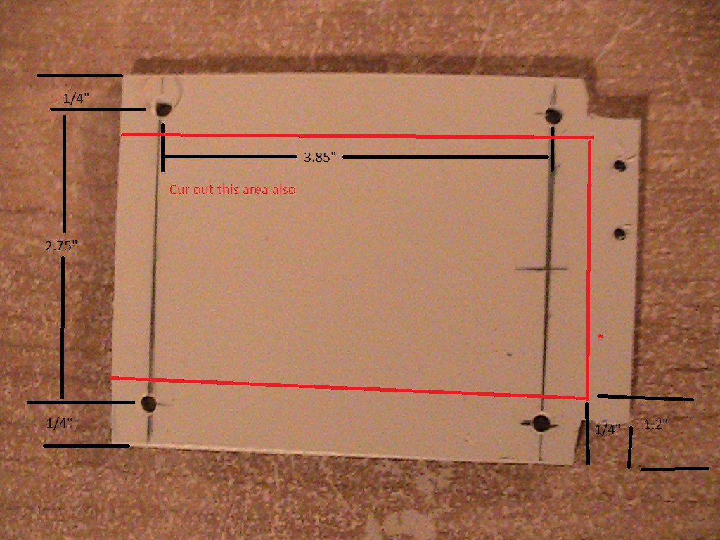
Use a small sheet of plastic and cut out a plastic square. For a plastic sheet, I used the bottom of an old keyboard (I never throw anything away…just ask my wife). Cut and drill to the dimensions below.
![]()
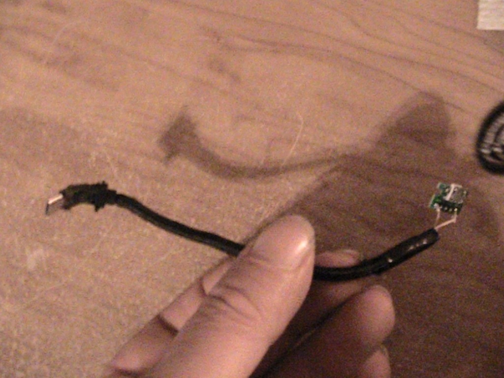
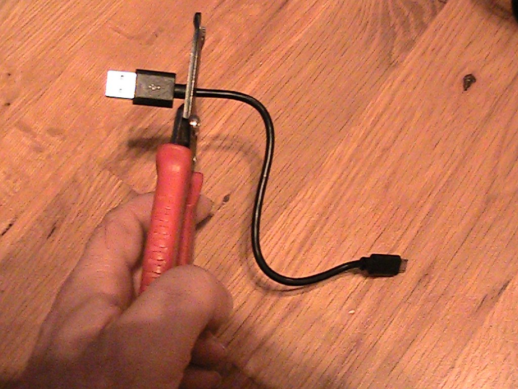
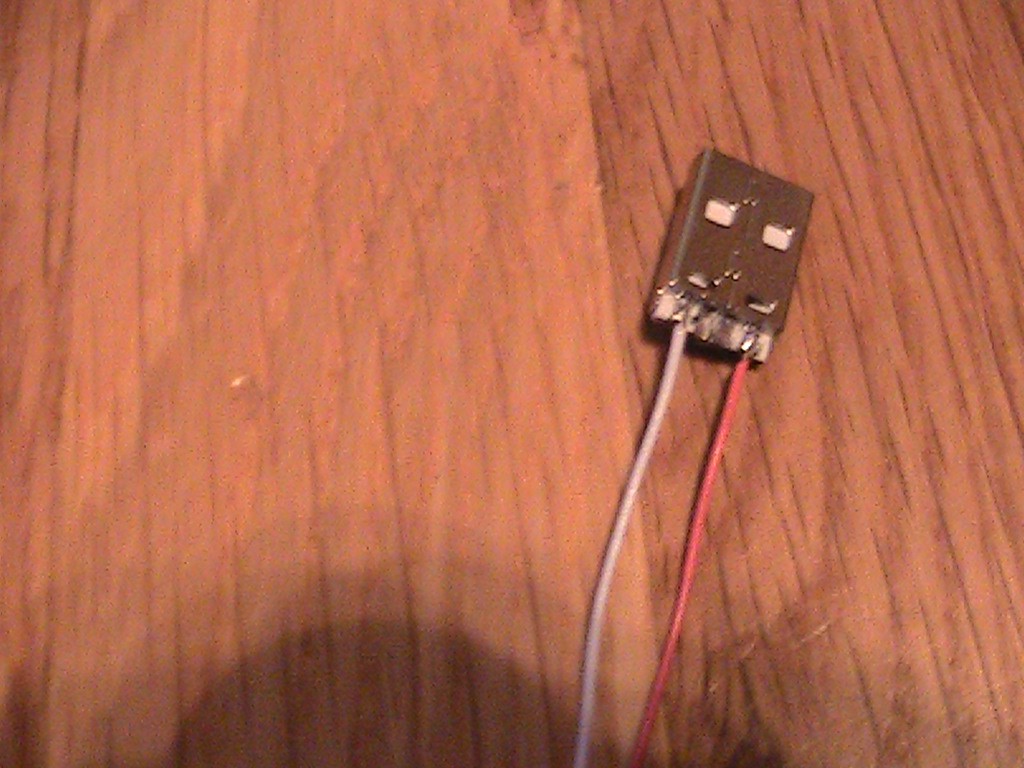
Take a USB charging cord and cut off the USB “A” end. Strip and solder the cut end to a USB Micro B break out board.
![]()
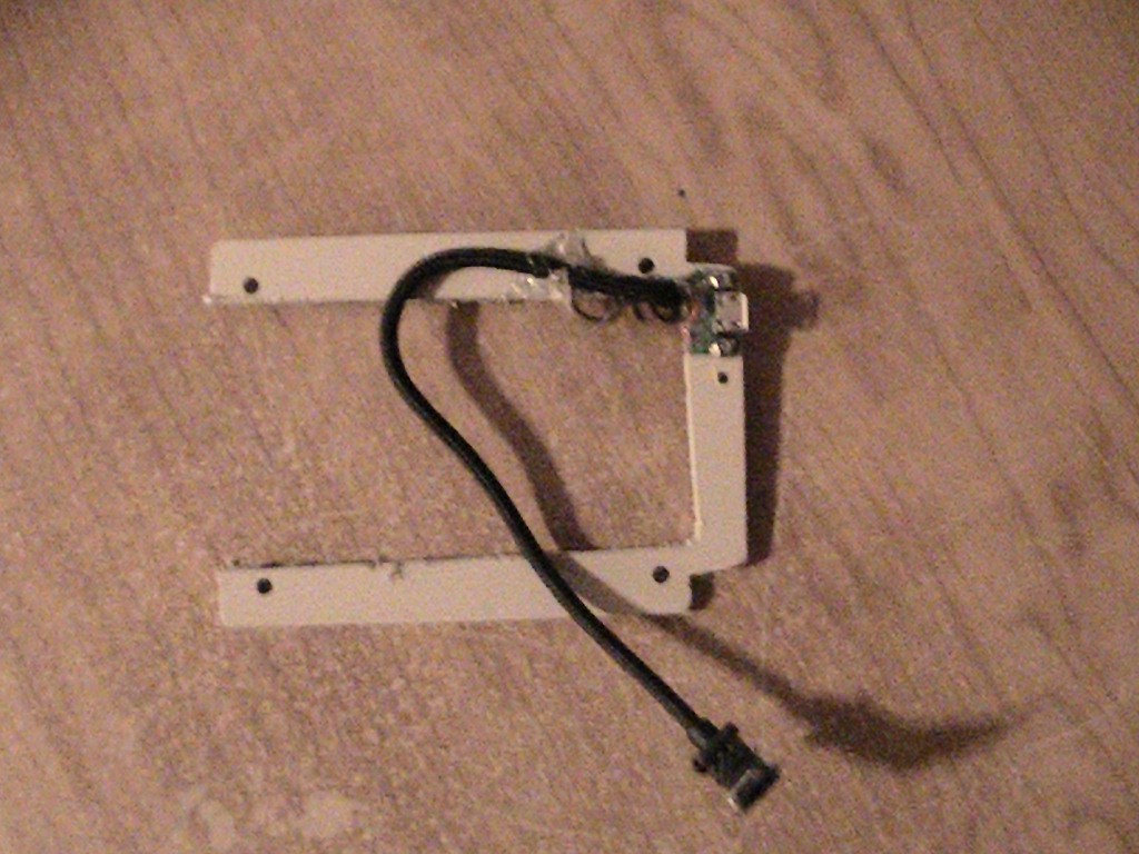
Mount the USB Micro B break out board to the plastic plate.
![]()
LC PI filter:
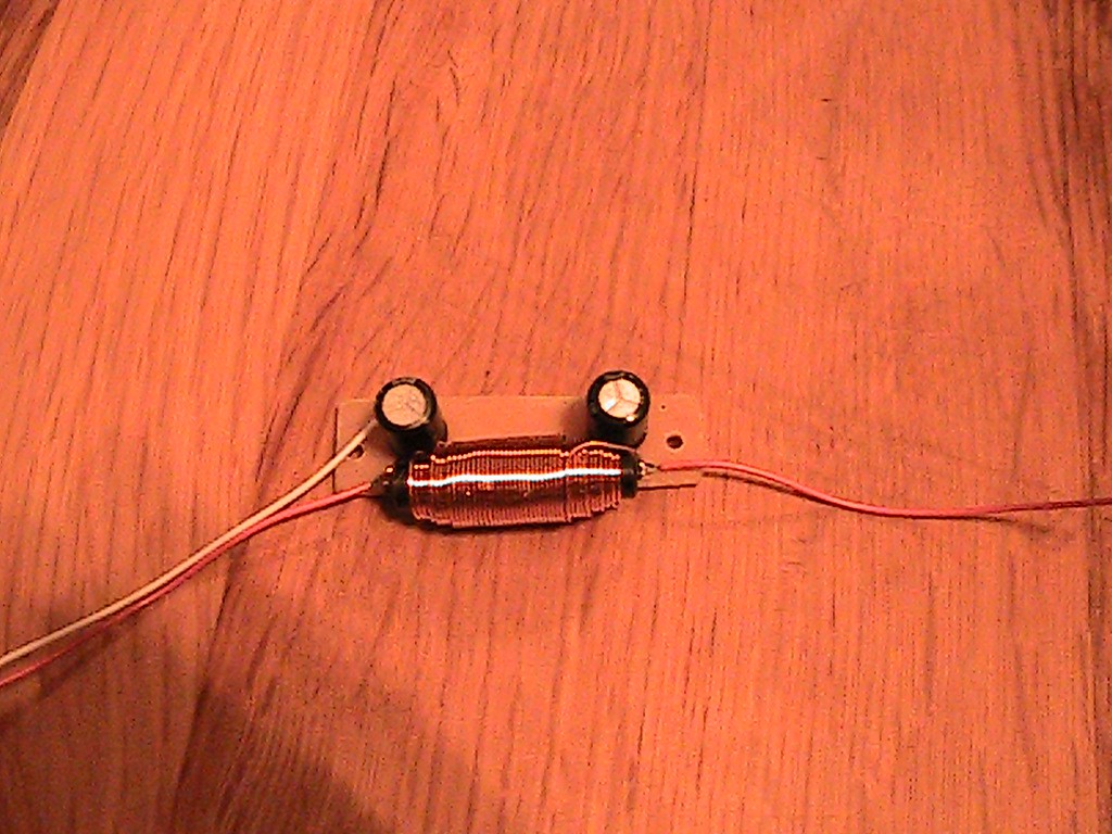
I home printed a board from the Gerber file located in “files” and located in the GitHub repository. Solder the two 47uF capacitors and the .1uH Inductor on the board as indicated on the below image. Also, solder two red wires to the two top terminals and a white wire to one of the common terminals.
![]()
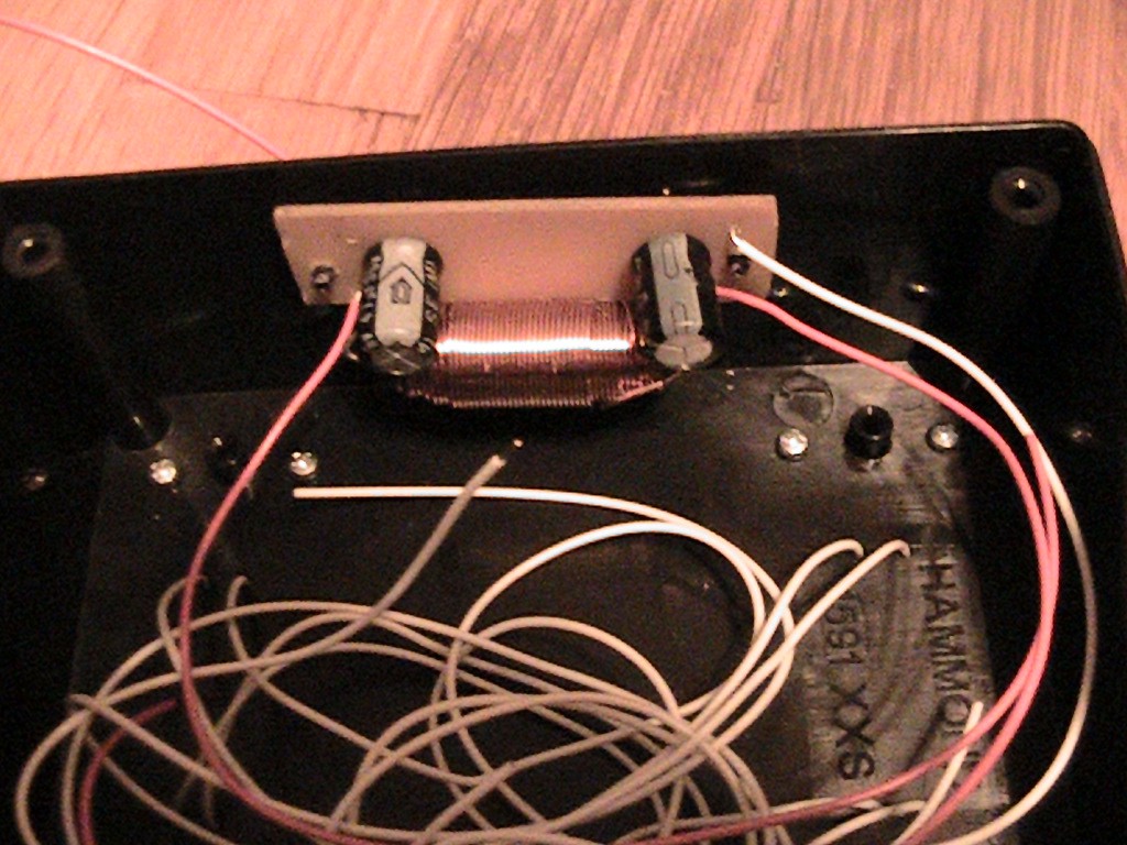
From 1.5 cm from the top of the right side of the box and 5 cm from the front of the box, drill a 1/8” hole in the box. Drill a second 1/8” hole 1.25” further back from the front hole. Carefully mount the LC filter board inside the box with two 1/8 x1/4” self-tapping screws as in the below image.
![]()
Power connections and forward pointing LEDs:
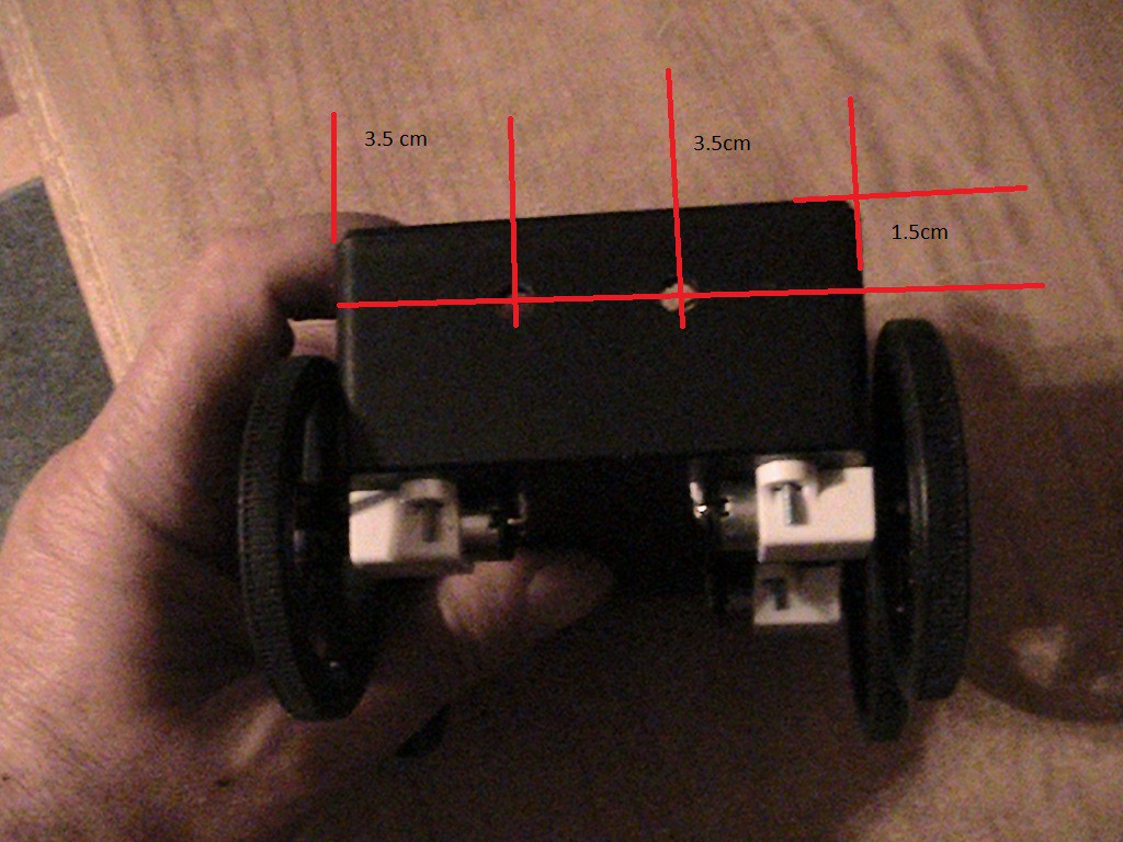
Drill two 5.7mm holes in the front of the box at the below dimensions. On the back of the box, drill a ¼” hole 2 cm from the left side and 1.5 cm from the top. On the right side, cut a slot for the charging port 1.2 cm from the bottom and 1 cm from the left side.
![]()
Mount the plastic plate into the mounting holes at the bottom of the box. Cut the “A” connector off of a USB cable 6” from the micro ”B” side. This cable will power the Raspberry PI.
![]()
Route the wire from the top through the ¼” hole and grommet on the box top drilled in an earlier step. Strip the cut end to expose the wires. Tape up the green and white wires.
On a USB “A” connector, solder a red wire to the positive terminal and a white wire to the negative terminal.
![]()
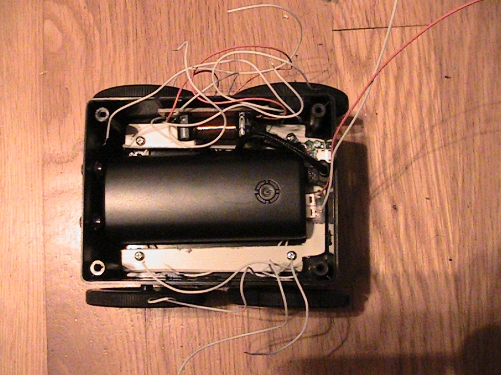
Insert the USB “A” connecter into the battery. Also, insert the micro USB charging cable into the battery that was prepared earlier. Press the battery into the bottom of the box. It should fit firmly in the plastic plate. Mount the power switch in the switch hole on the back on the box. I’m using a single pole double throw switch, but a single pole single throw switch will also work. The assembly should look like the one below.
![]()
Solder the red wire from the battery to the armature of the switch. Solder one of the red positive wires from the LC PI filter, the red wire from the USB cable the routed through the box top to the other switch terminal. With a small wire nut, connect the negative wire from the battery, the negative wire from the USB cable routed through the top of the box and the white wire from the LC PI filter together. I soldered them together then put the wire nut on just to ensure a good connection. Next, connect the second power wire from the LC PI filter and the red wire from the upward pointing LEDs together in TB5.
Insert two LED holders and LEDs in the front of the box. Solder the two anodes together with a red wire. Solder a white wire to each of the cathodes. Connect the positive wire to a Molex female connector pin. Connect the two anode wires to the other two pins, it does not matter which one goes to which pin. Plug the Molex connector into the Molex connector on the motor drive board.
Motor connections
Connect each of the two motors on the left side of the bot to the two TB3 and TB4 on the motor drive board. Again, it does not matter which motor connects to which TB. They will be working in tandem. Connect the two motors on the right side of the bot to TB1 and TB2.
Next, turn the power on the InspectorBot and copy the program Motor_test.py from the files section of the page to the Raspberry PI. This program will test the motors and the LEDs. It will first turn on all LEDs and turn on all motors in the forward direction. It will then turn the LEDs off and turn the motors to pan the robot right, then left and last reverse. If any of the motors rotate in the wrong direction while the LEDS are on, then switch the wires for that motor at the TB on the motor drive board. If and LED or motor does not come on, double check the connections.
Put the top of the box on the bottom and that concludes the mechanical build!
-
6The Software
Starting at this step, I am assuming there is already a Raspberry PI loaded with an operating system and the PI is connected to WIFI. I am using “NOOBS” and WinSCP to load files to the PI. You will also need access to the terminal and VNC. In VNC, go into configuration and enable the camera. InspectorBot is controlled through a built-in Webpage so you will need to load the following:
First, get the latest version In terminal:
sudo apt-get update
sudo apt-get upgrade
Load:
Apache2
sudo apt-get install apache2
PHP5
sudo apt-get install php5
Motion
sudo apt-get install motion
Motion will need the following changes in its config file In terminal:
sudo nano /etc/motion/motion.conf
Make sure 'daemon' is ON.
Set 'framerate' 100
Change 'Stream_localhost' to OFF.
Change 'webcontrol_localhost' to OFF.
Set 'width' & 'height' to 640 & 480
At the bottom find #thread1 and #thead2 and remove the “#” from both.
In terminal, allow access etc/motion
sudo chown -R pi / etc/modules
Copy thread1.conf and tread2.conf from files on this page and with WinSCP, copy them to etc/motion. This will allow InspectorBot to stream both cameras at the same time.
Allow access to www/html
In terminal, allow access to www/html
sudo chown -R pi /var/www/html
After installing Apache2, there will be an index.html file located in www/html. Copy the index.html file from files in this webpage and with WinSCP replace the index in www.html with the one from files. Add two new folders to www/html. Name one “commands” and one “AJAX.” Copy the following files from files on this webpage, and copy them in the folder named “commands.” “floff.php, flon.php,forward.php, left.php,right.php, reverse.php, slow_left.php,slow_right.php, uploff.php and uplon.php” These are the server side PHP script to control the motors and the LEDs. Copy this file “jquery.min” from this webpage and copy it in the file named “AJAX”. This allows the buttons to work.
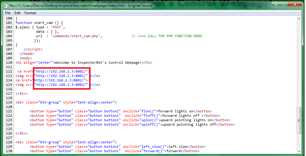
The index.html will also need the following field’s changes to the IP address that the PI is connected to.
![]()
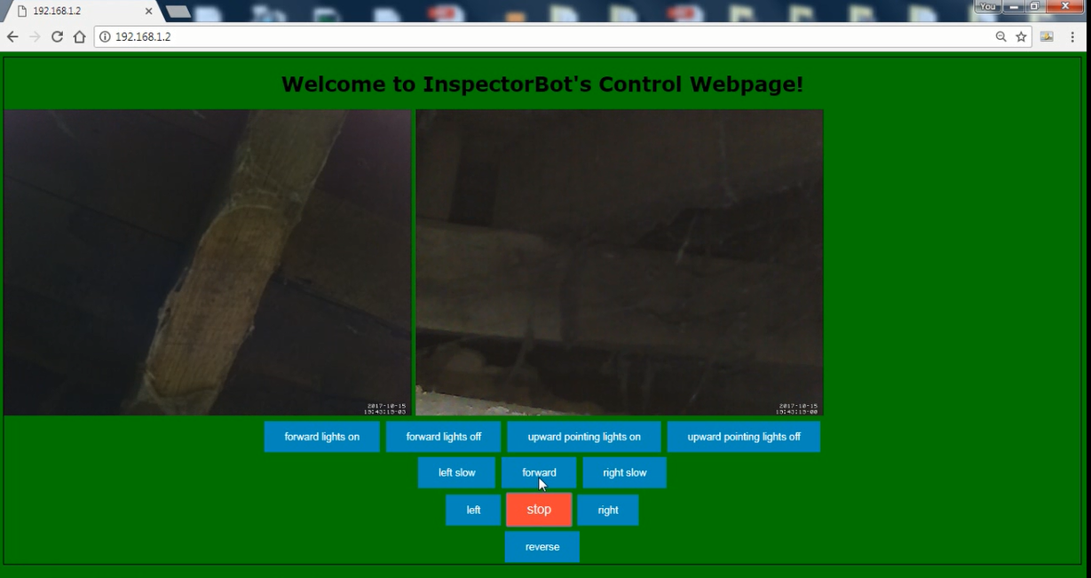
This is where the InspectorBot’s webpage streams the two cameras. After completing these steps, open a browser, preferably Chrome or Firefox, and enter the IP address the PI is connected to, and you should get the below webpage.
![]()
The control buttons are very straight forward. When you press “forward”, the bot will move forward until you press “stop”. The only exceptions are “left_slow” and “right_slow”. These buttons will cause the bot to rotate for ½ second. To rotate the bot slowly, just keep tapping one of these buttons.
Congratulations! Now you have a working InspectorBot!
InspectorBot
An open source robot to inspect under vehicles, crawl spaces and any other dark dirty space you need to take a look at.
Discussions
Become a Hackaday.io Member
Create an account to leave a comment. Already have an account? Log In.