-
High Definition pics inside and out
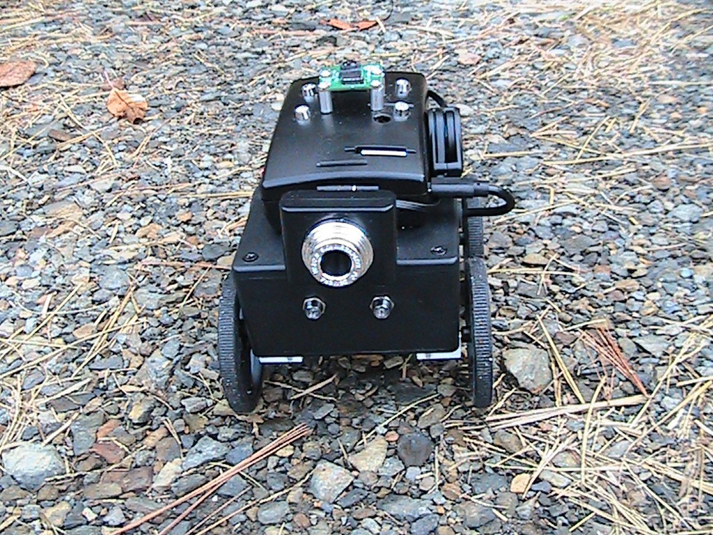
10/21/2017 at 04:58 • 0 commentsFront view of low definition camera and forward pointing LEDs
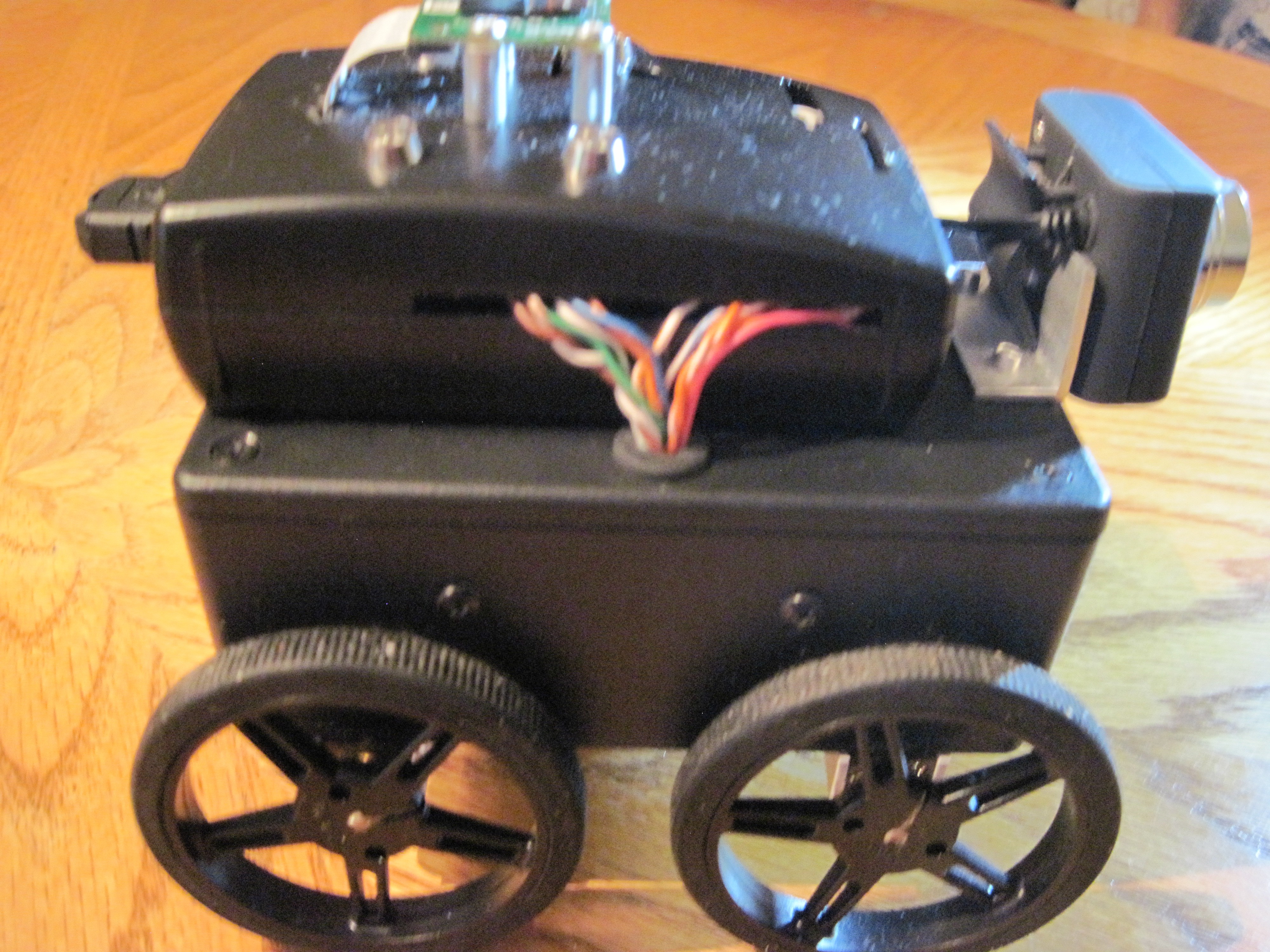
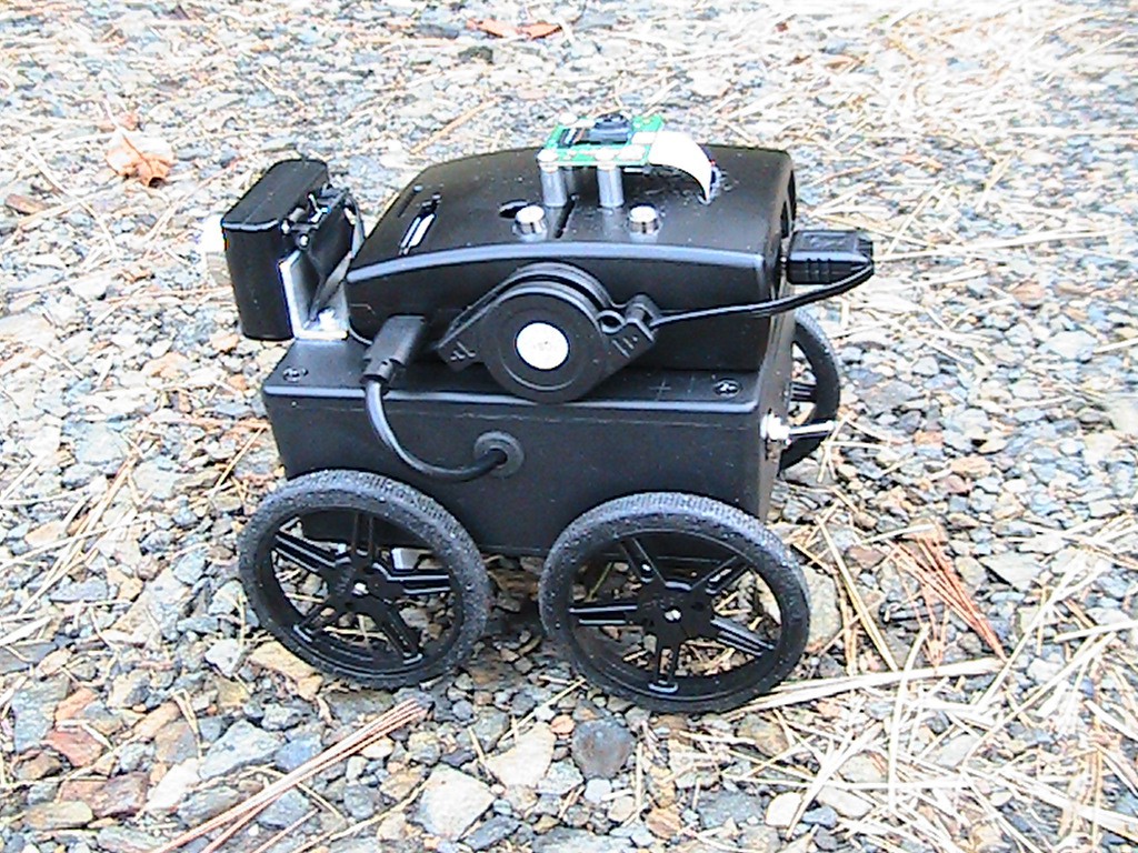
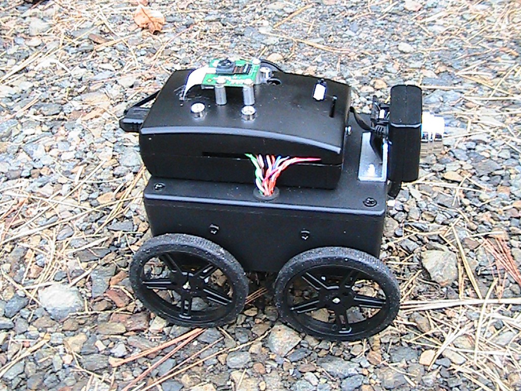
Both sides.
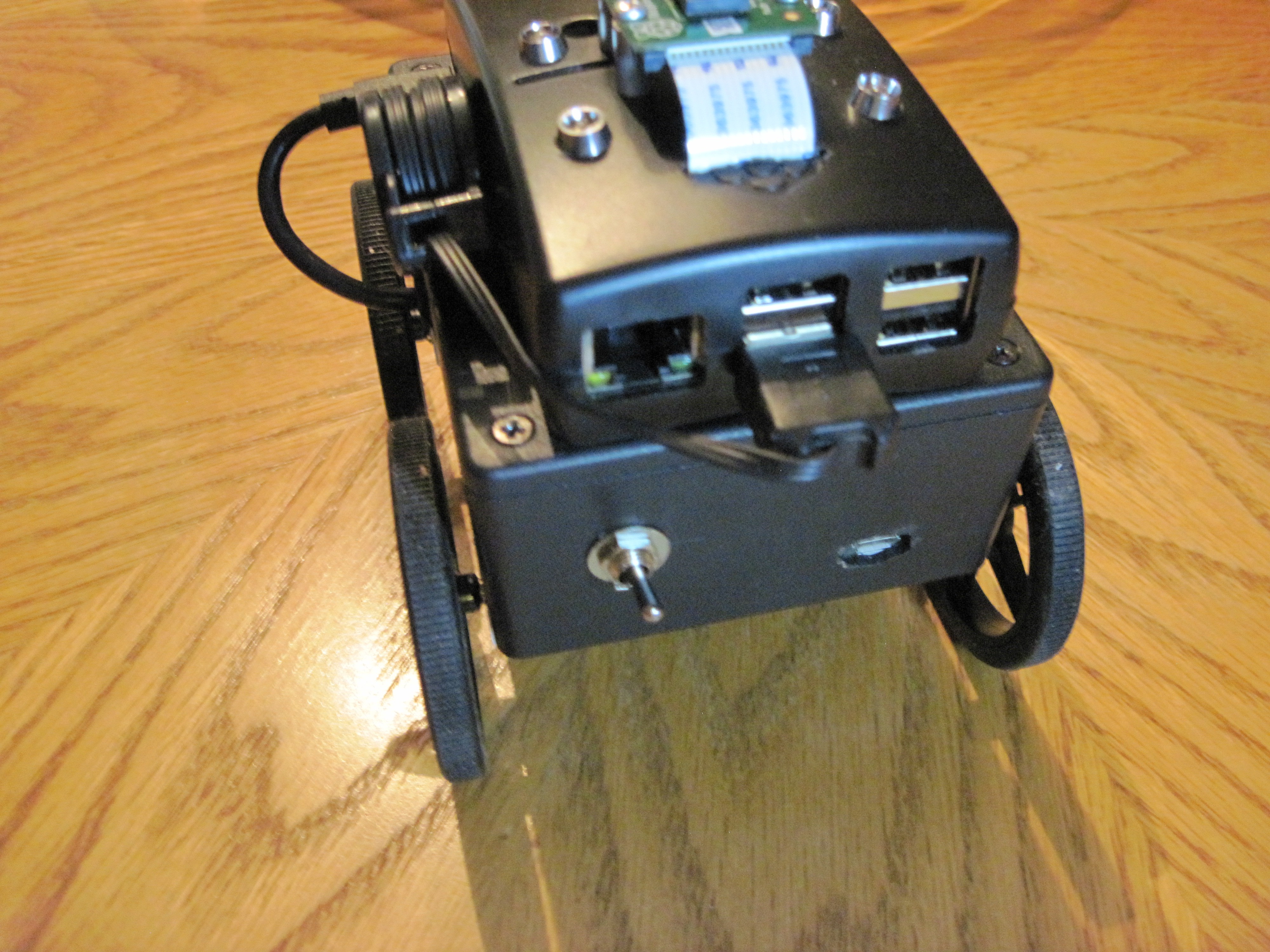
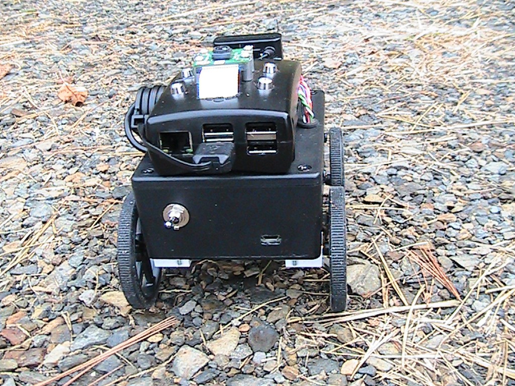
Rear showing power switch and USB charging port.
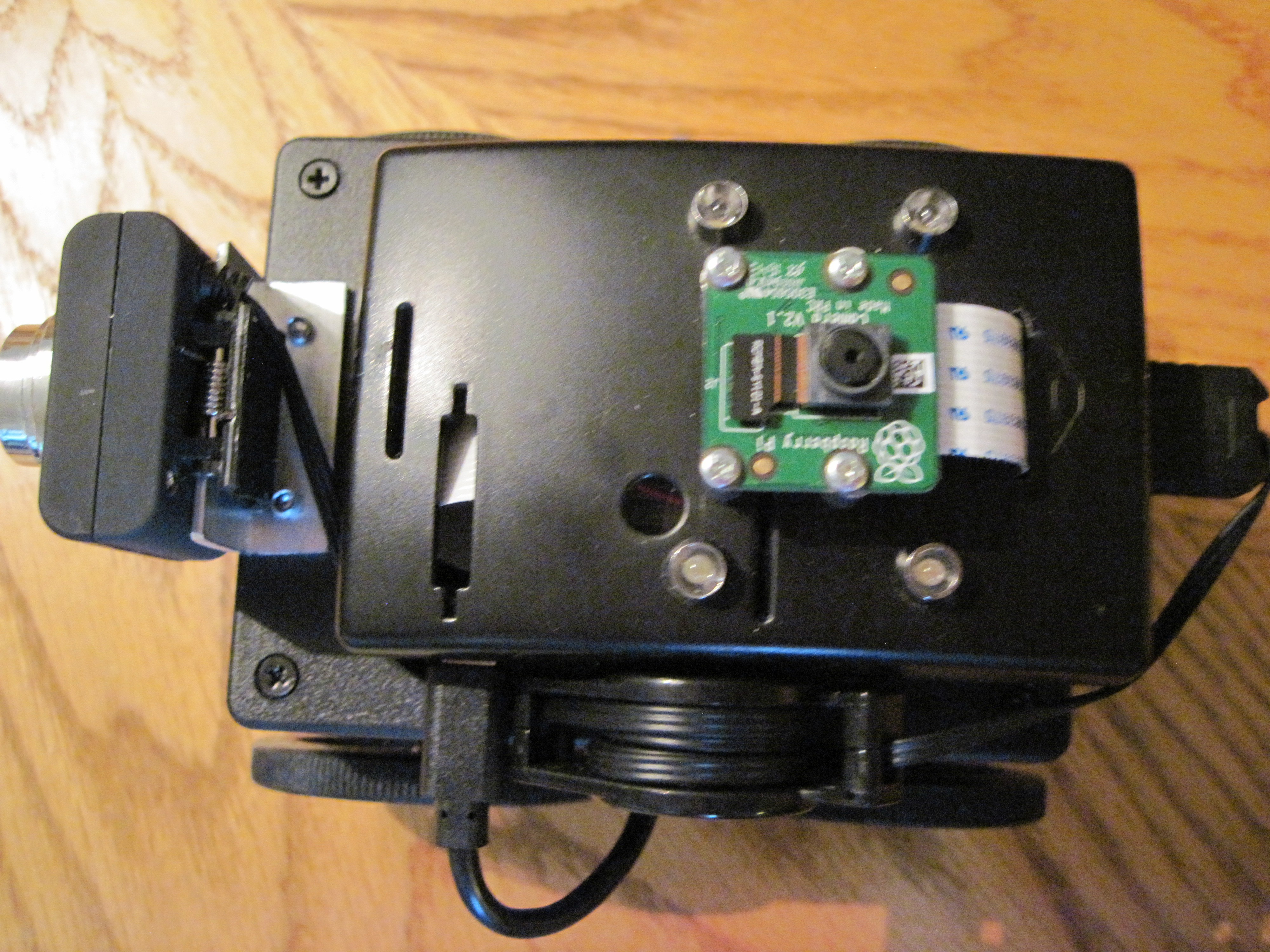
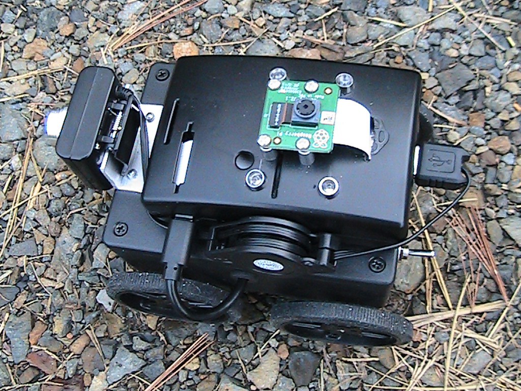
Top view showing High Definition Camera and upward pointing LEDs.
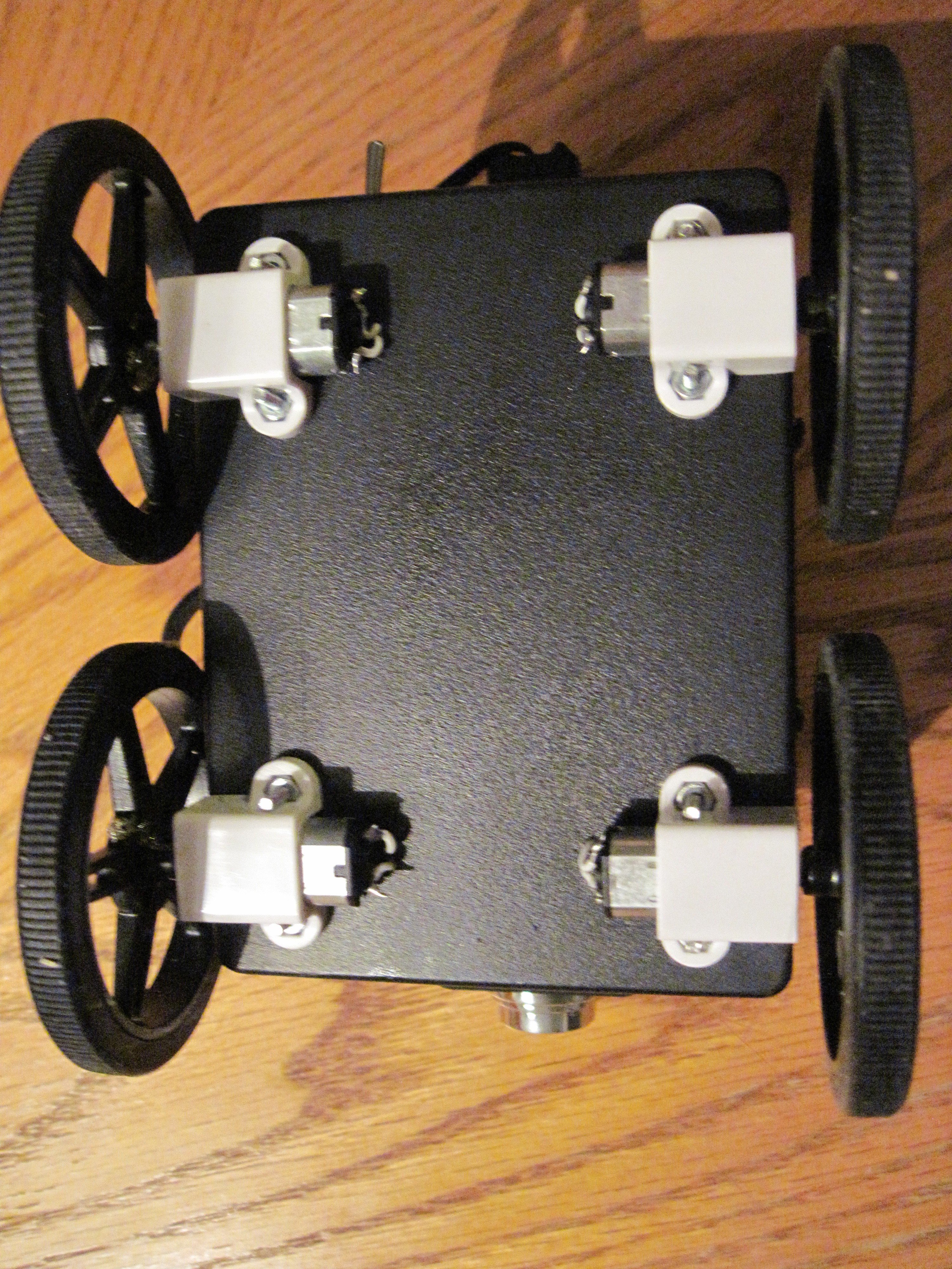
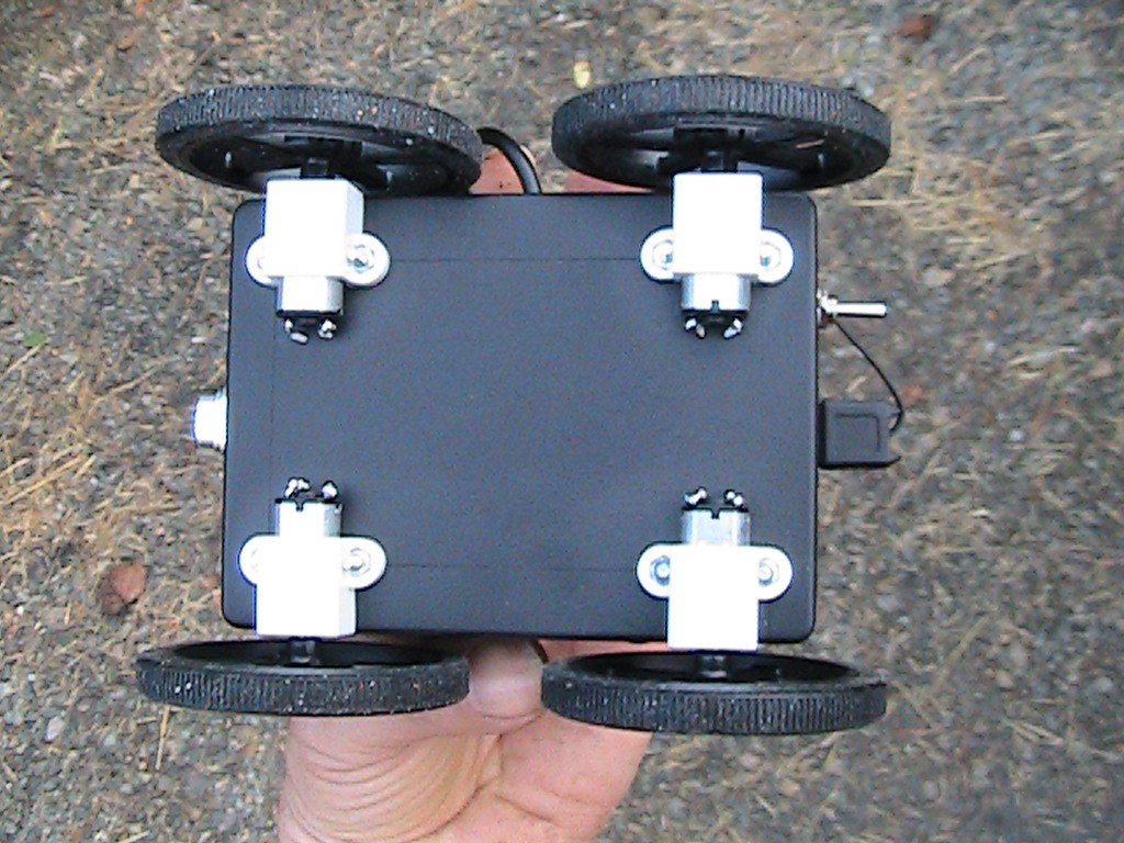
Bottom view showing m20 gear-head motors.
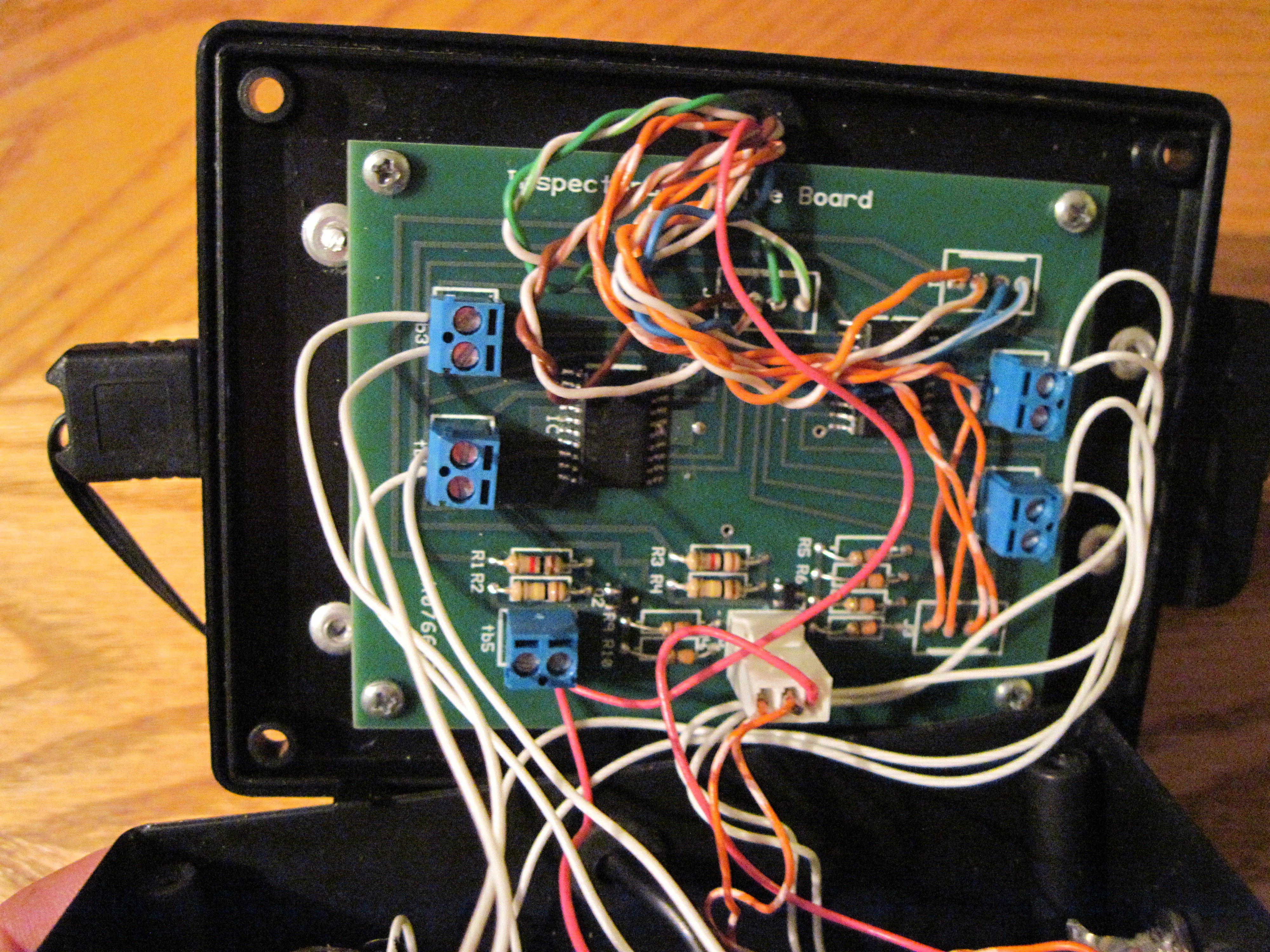
motor drive board.
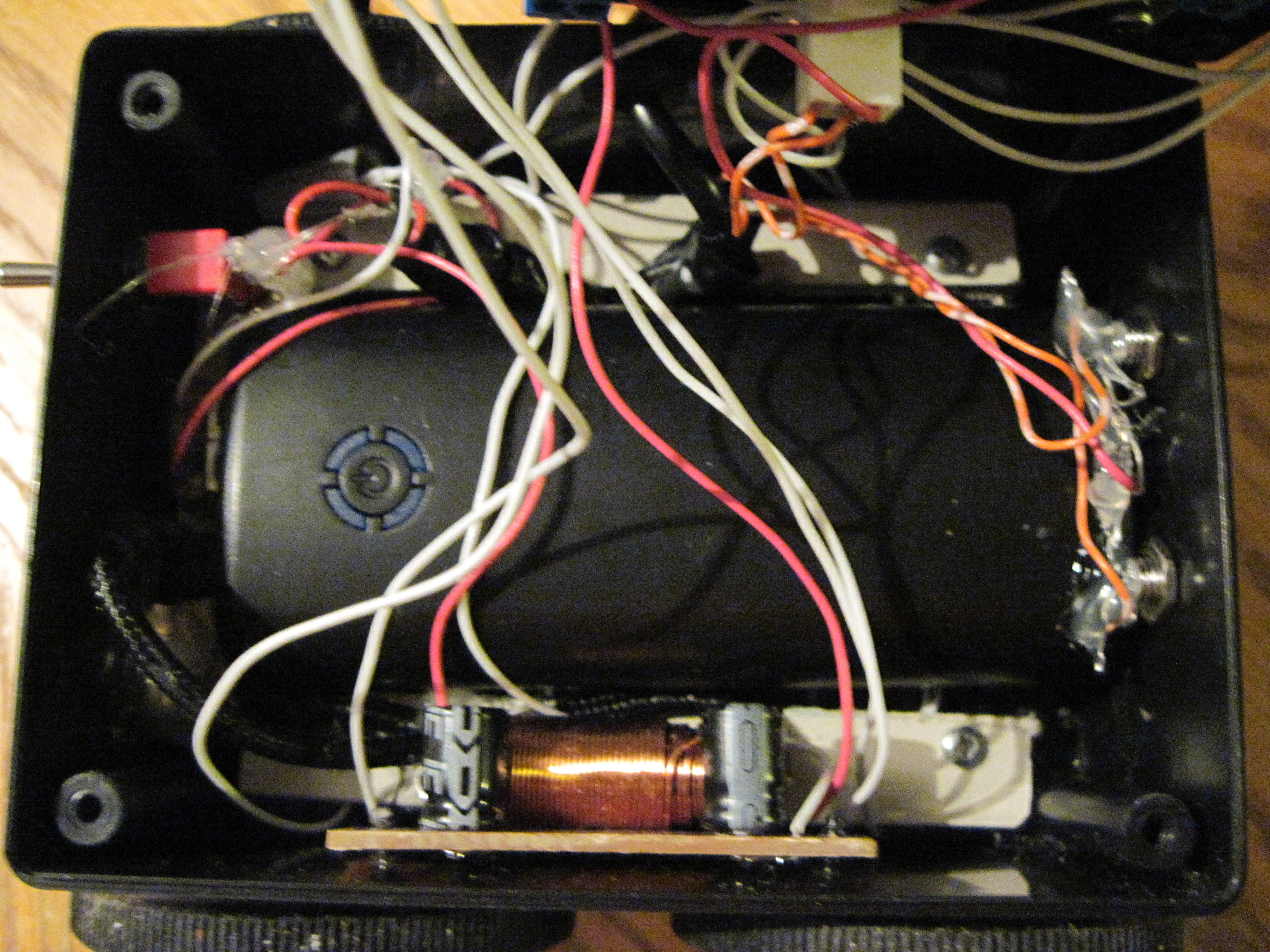
Inside the box.
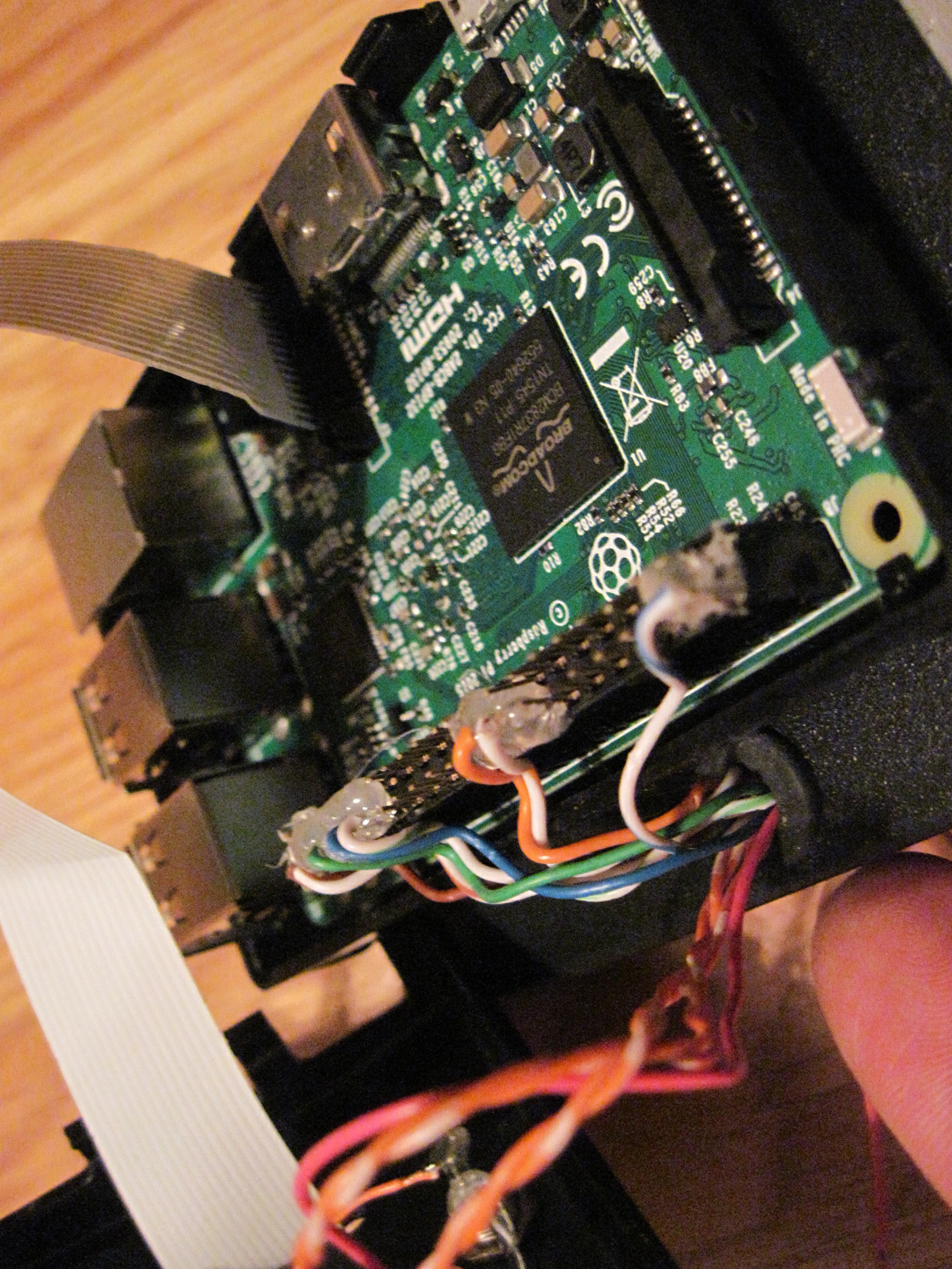
Inside the PI case.
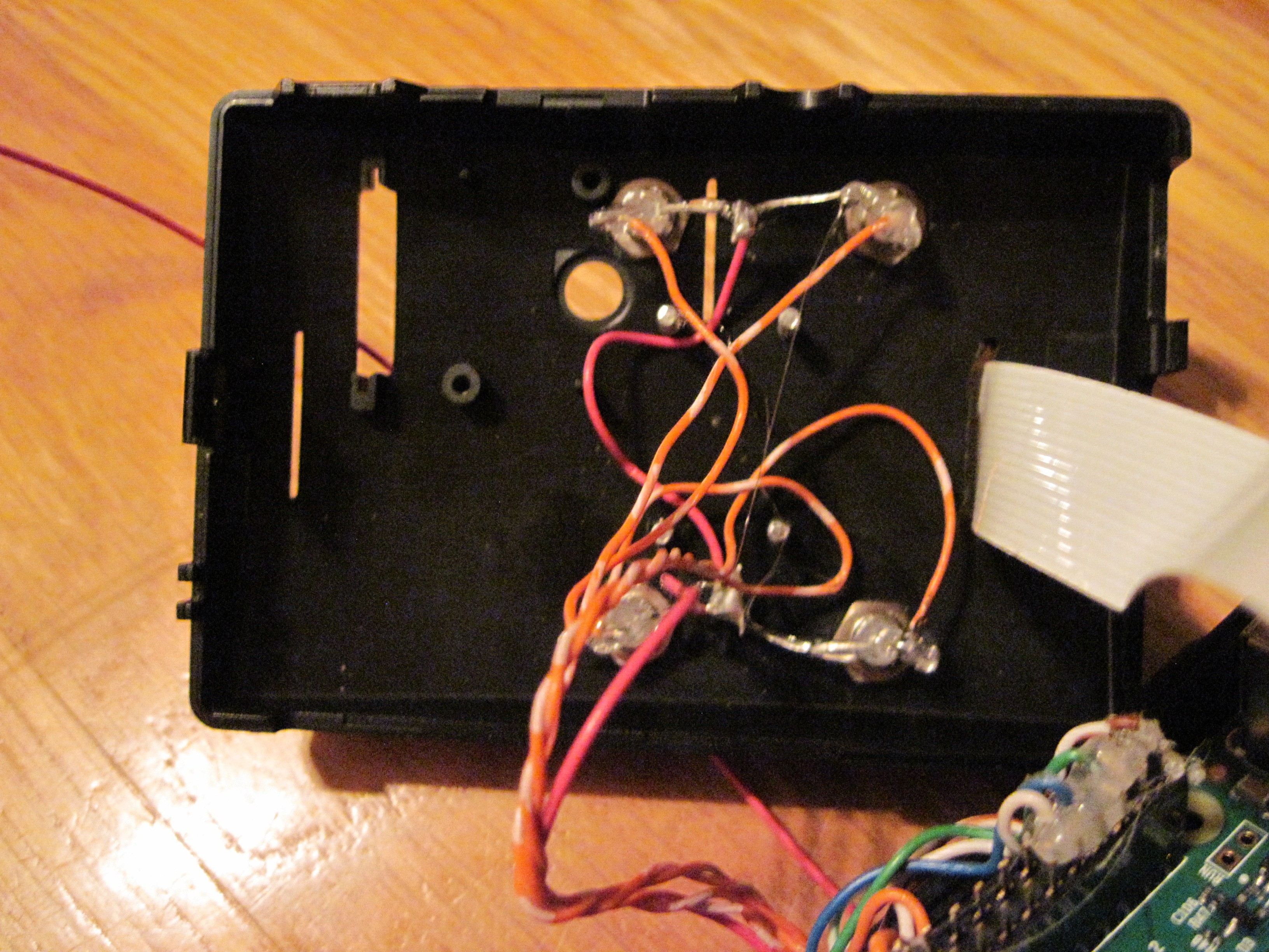
Inside the top of the PI case showing the upward pointing LEDs.
-
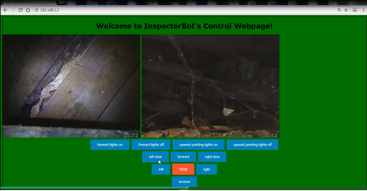
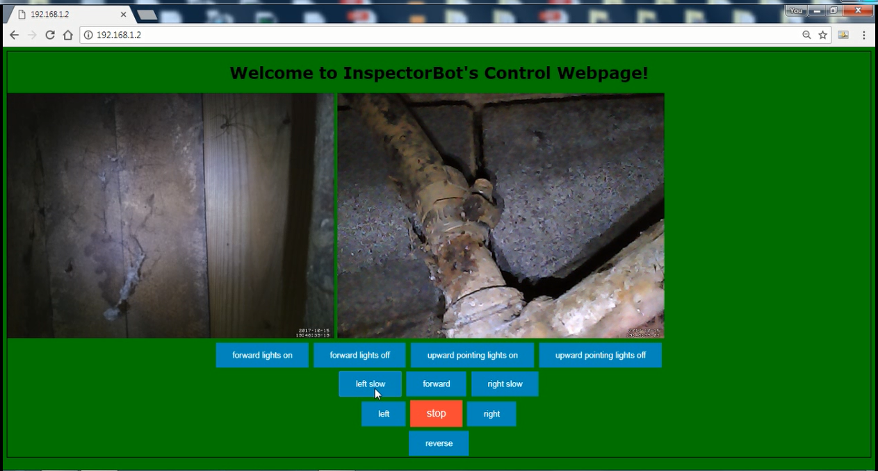
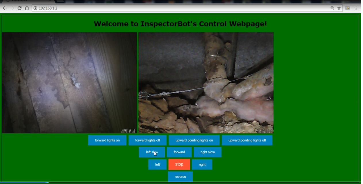
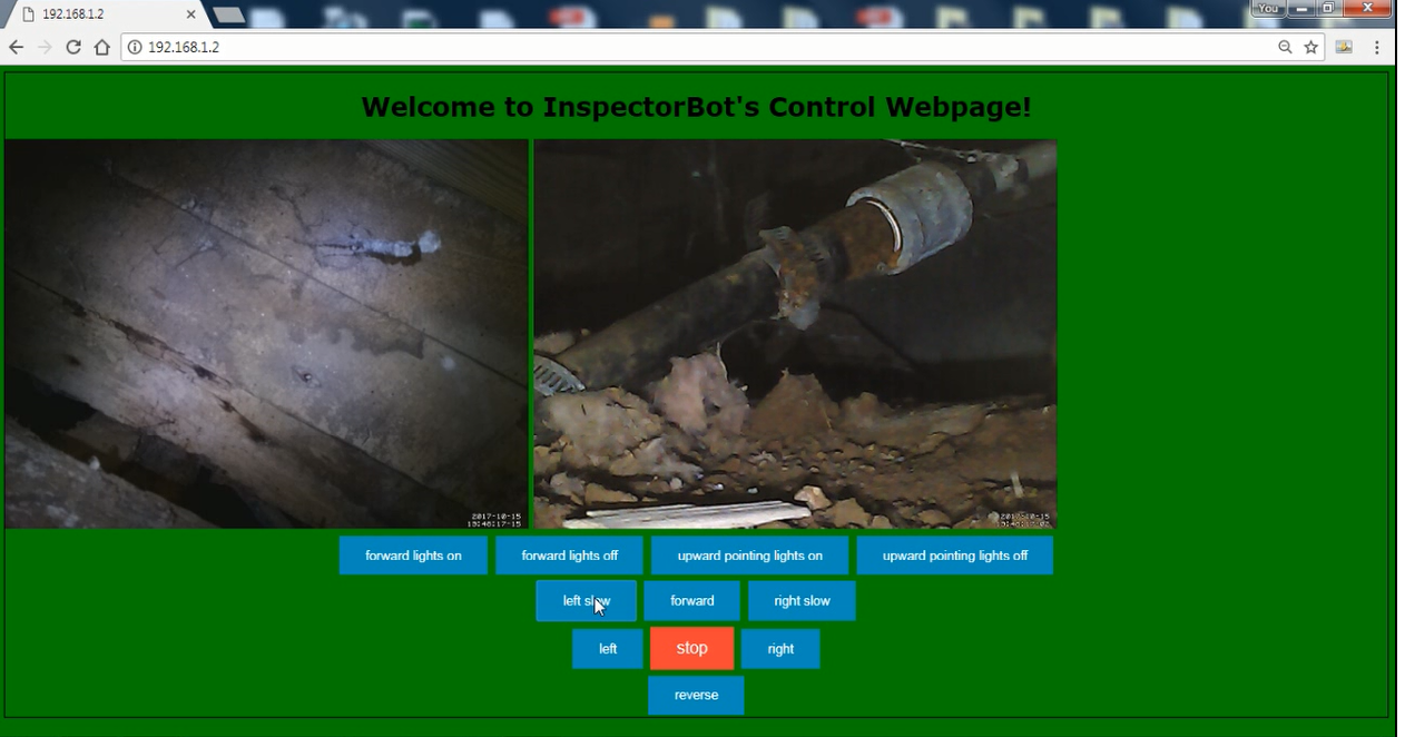
Shots from under a house.
10/18/2017 at 10:20 • 2 commentsImportant note! When exploring under your Moms house, it may not be good if she is watching. Especially when you come across a snake skin! This is also a great reason to send the InspecrorBot first.
![]()
A few pictures of questionable pipes and sub-flooring
![]()
![]()
![]()
-
The finished InspectorBot!
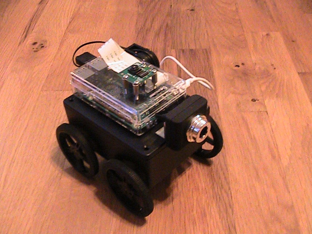
10/15/2017 at 12:55 • 0 commentsHere are a few pictures of a finished InspectorBot. Sorry for the bot being a little dirty. It has been out for a few test drives. I have found it is amazingly fun to drive.
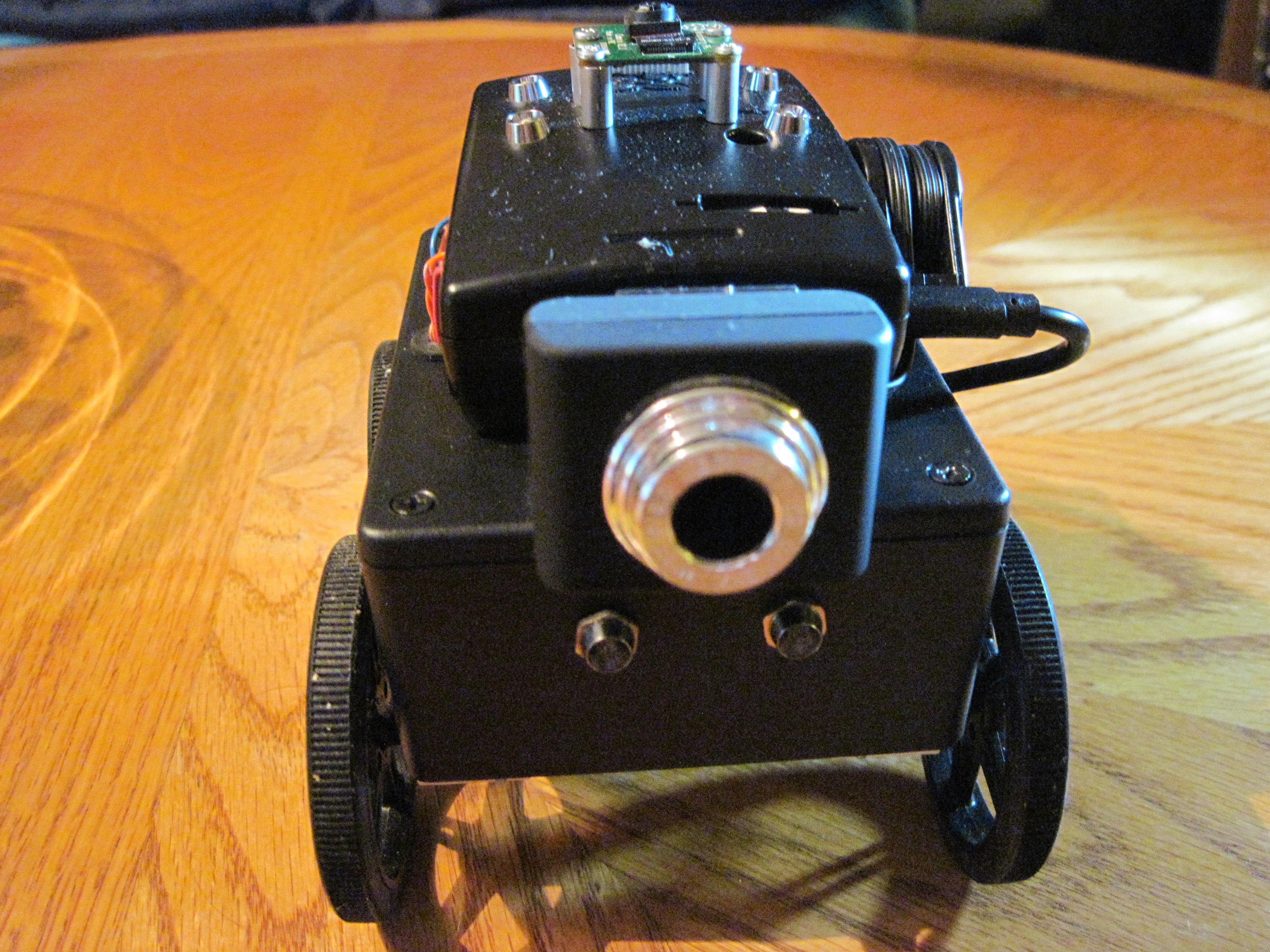
The below picture of the front end shows the low definition camera and the forward pointing LEDs.
The top view shows the High definition camera and the upward pointing LEDs.
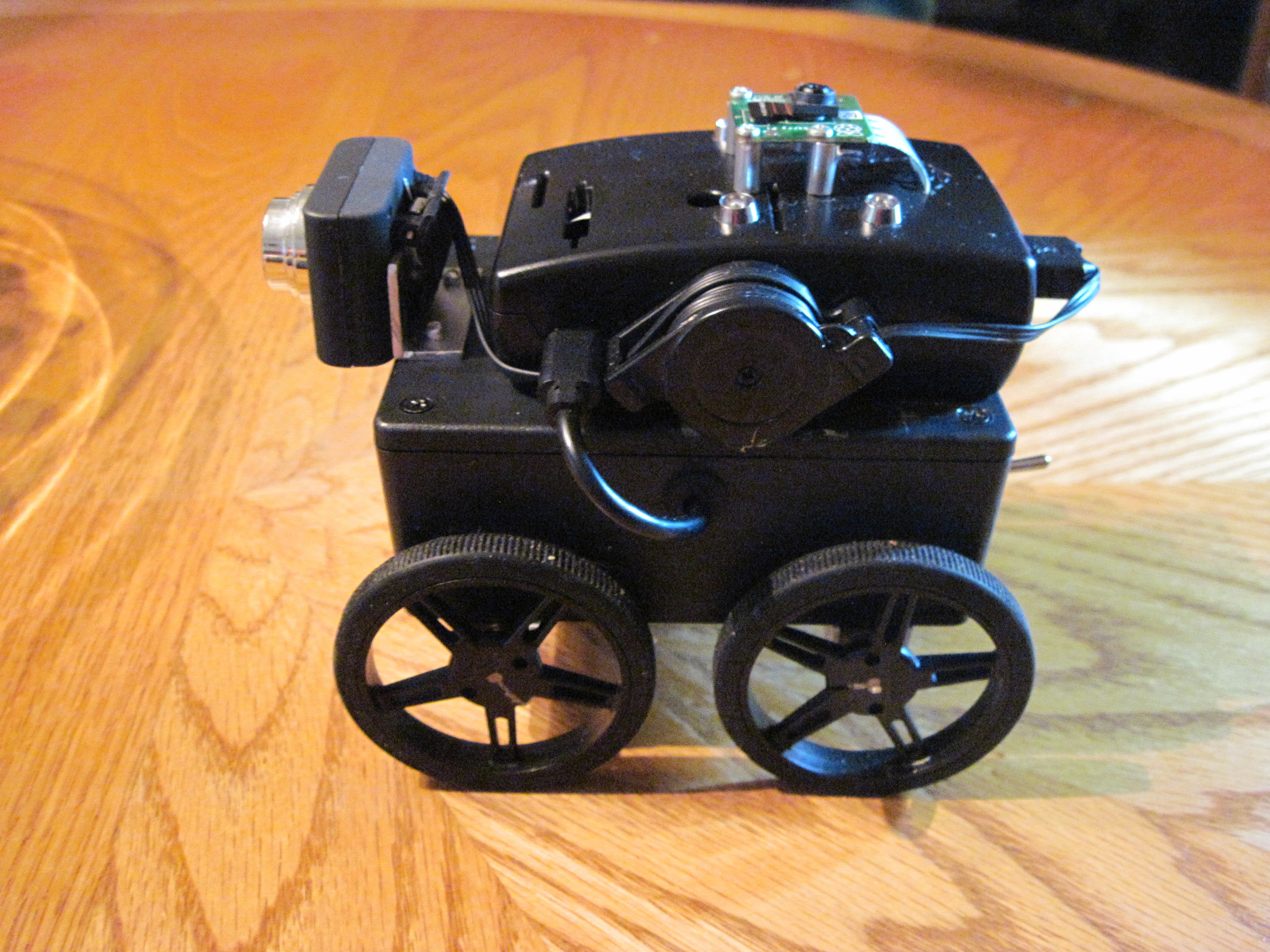
The side views.
The rear view shows the power switch and the USB charging port.
And last, the bottom view showing the four motors.
-
Power filter
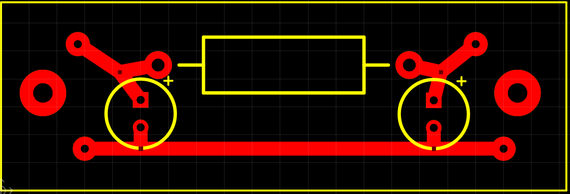
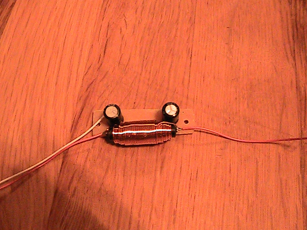
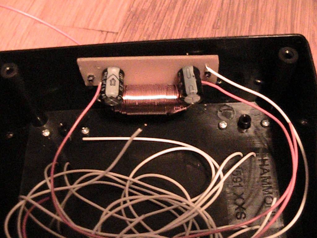
10/08/2017 at 17:52 • 0 commentsWhen both the motors and the controller board are powered from the same battery, motor noise can cause lots of problems for the controller. One of the best ways I’ve found to clean up the motor noise is an LC pi filter. Here is a quick easy filter to clean up the noise. To save time, I printed the boards. I added the Gerber files to both files and repository to make it easy to reproduce. It just has three components: two 47uF capacitors and one 1mH inductor. Wires are soldered directly to the board. An input power from the battery switch, an output power connected to the motor board and a common.
![]()
![]()
Below is how the board looks and also mounted in an InspectorBot.
-
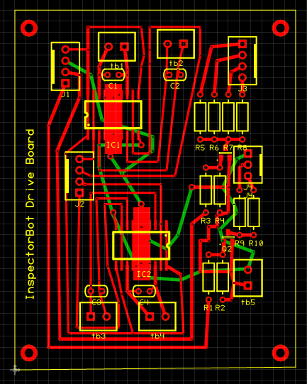
Adding Gerber Files for InspectorBot’s Motor Drive Board.
09/14/2017 at 15:56 • 2 commentsThe Gerber File for InspectorBot’s Motor Drive board is now in the repository and under files in a ZIP format.
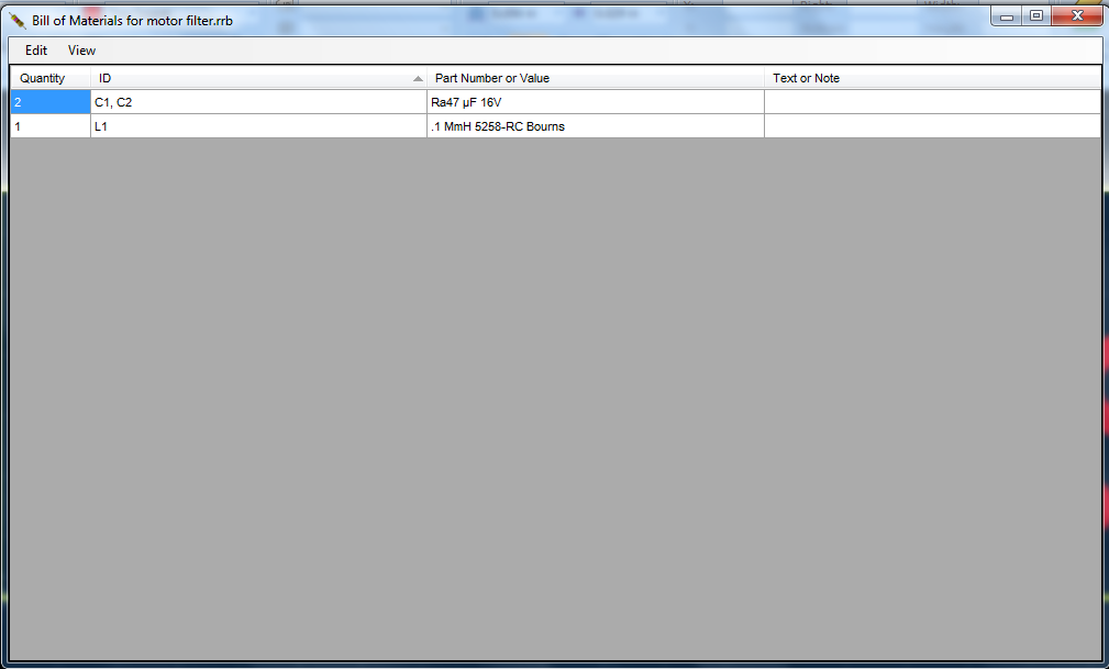
Below is an image of the board and the BOM for the board.
![]()
![]()
-
Adding the gearhead motors and wheels.
09/10/2017 at 02:08 • 0 commentsI decided on the m20 gearhead motors for InspectorBot. They are small but still generate a comfortable level of torque to move the bot. The m20 I’ve selected run at 50 RPMs at 6 volts. The wheels I’ve selected have a 60mm diameter or around a 2.36” diameter. That’s a circumference of 7.4” or 18.8 cm, so at 50 rpms, the bot will travel around 6 “per second or 15.2 cm per second. That is a comfortable speed to control a small bot.
I also wanted to find an easy way to attach the m20 gearhead motors to the robot’s box. I found the Pololu Micro Metal Gearmotor Extended Bracket worked nicely. I’ve added the measurements to the build instructions. Below is how the Bot looks with the new wheels.
-
InspectorBot’s motor drive board
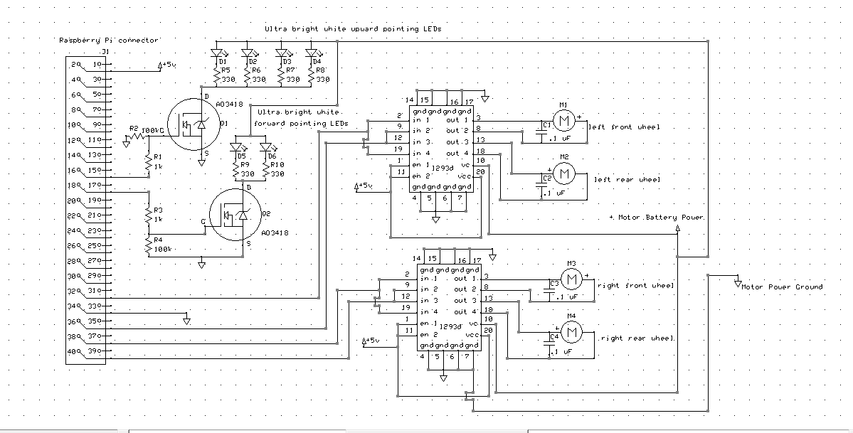
08/15/2017 at 02:13 • 0 commentsInspectorBot’s motor drive is based on the L293d dual h-bridge. As a 4-wheel drive robot, InspectorBot has four gearhead motors--one for each wheel. The motor drive board contains two L293d h-bridges. One L293d drives the motors on the left side of the bot, and the other L293d drives the motors on the right side of the robot. This allows each gearhead motor to have its own independent driver. The L293d has built-in diodes to shunt the back EMF from the motors, but I still prefer to add .1 micro farad capacitors across the motor leads to reduce motor noise. The board also contains two HEXFET transistors. One HEXFET drives four upward pointing LEDs to light up the area above InspectorBot to allow the upward pointing high definition cameras to take better pictures. The second HEXFET drives two forward pointing LEDs to allow a user to see in front of the robot in dark spaces, such as crawl spaces.
![]()
-
Forward pointing and upward pointing cameras running at the same time.
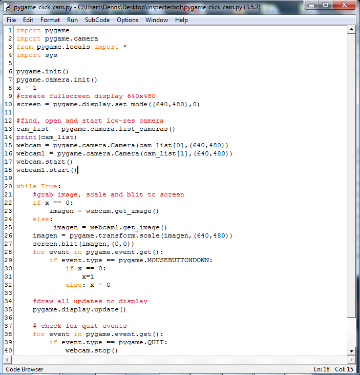
07/24/2017 at 01:18 • 0 commentsHere’s a short python program to test if both cameras can be operated at once. The program sets up and starts both the low definition forward pointing USB camera and the high definition Raspberry PI V2 upward pointing camera. The program uses a “MOUSEBUTTONDOWN” event to tell the program to switch the display between the cameras.
![]()
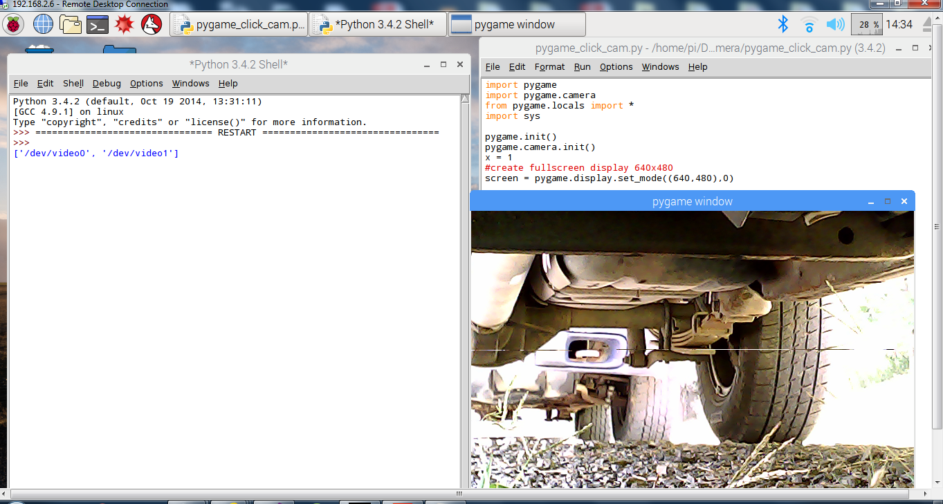
Below is an image of the program displaying the forward pointing camera from underneath a vehicle.
![]()
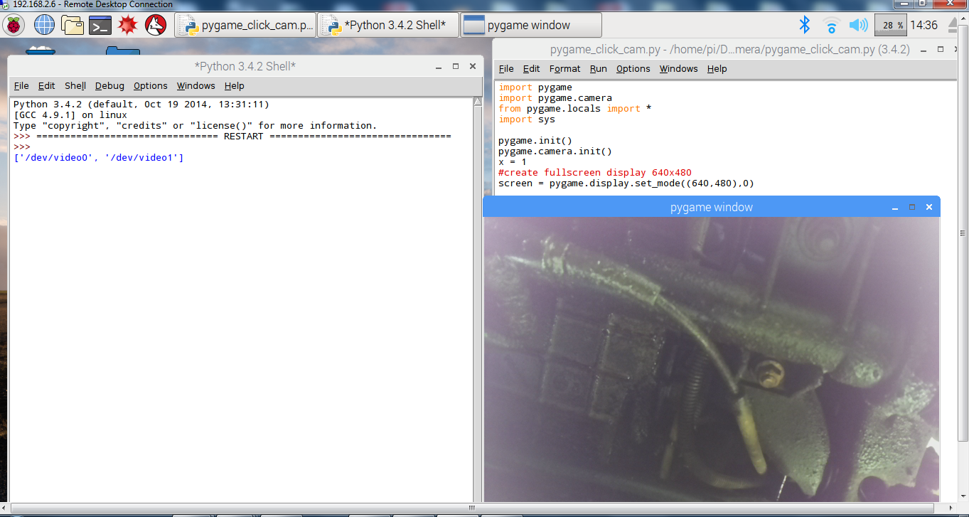
After clicking on the image, the display switched to the upward pointing camera. I will need to add lighting LEDs to get better upward pointing images and also forward pointing LEDs for driving around in crawl spaces.
![]()
After clicking the image several times, the image switches back and forth between cameras without a problem. The good news is it works! :) The bad news is I have an oil leak. :(
-
Raspberry pi camera v2
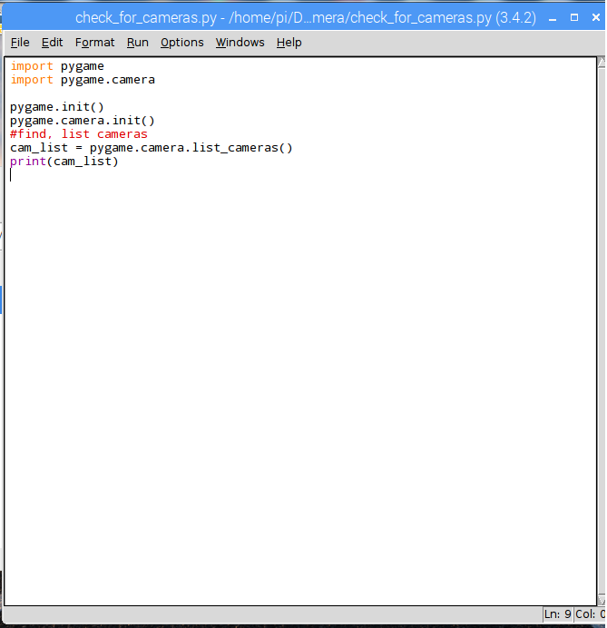
07/06/2017 at 00:07 • 2 commentsFor the time being, I wanted to work with pygame to access and display the cameras. Pygame makes it easy to add a USB camera, but a little more challenging to add the second High definition Raspberry Pi camera v2. Below is a short program to display the cameras attached to the RPI that are detected by pygame. I gave it the original name of “check_for_cameras”. The USB camera is plugged into a USB port and the Raspberry pi v2 camera plugged into the camera port.
![]()
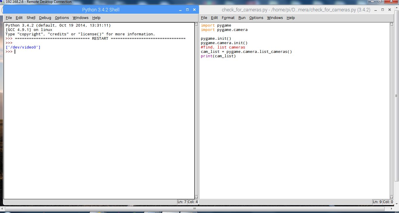
Now run the program.
![]()
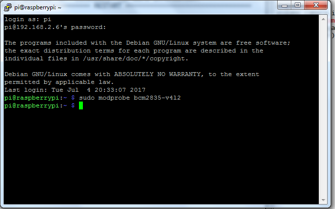
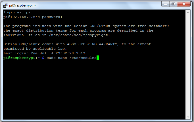
The program shows the problem. With the USB cameras plugged in and the Raspberry pi camera v2 plugged into the camera port, the program only displays the USB camera. To be able to access the Raspberry PI camera with pygame, we need a driver. Open the terminal and enter the command “sudo modprobe bcm2835-v4l2” like the below picture and run the program again.
![]()
![]()
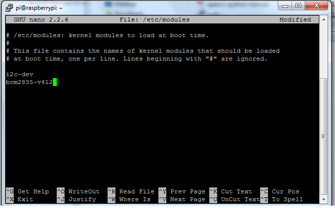
***I edited this section on Radomir Dopieralski advice and placed bcm2835-v4l2 in /etc/modules instead of /etc/rc.local. Thanks Radomir it works GREAT! ***
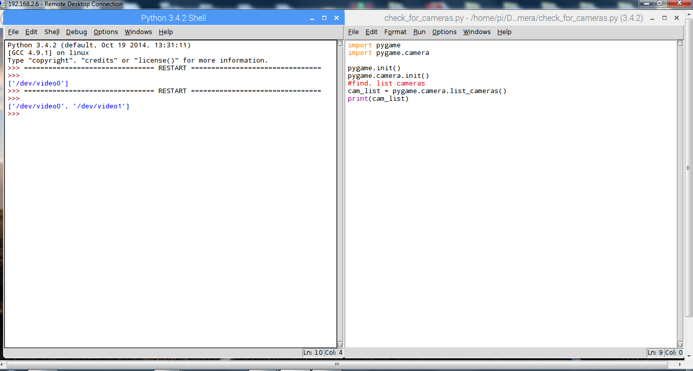
It worked! We can see both cameras. The next problem is it will only work until we reboot the Raspberry Pi. To get around this, we will need to run “sudo modprobe bcm2835-v4l2” at start up. To run the command at start up, open terminal and enter “sudo nano /etc/ modules” then add “bcm2835-v4l2” in the following window. Like the two pictures below and save the change.
![]()
Finally reboot the Raspberry PI and run the program, and both cameras should be detected.![]()
-
Low Resolution Camera
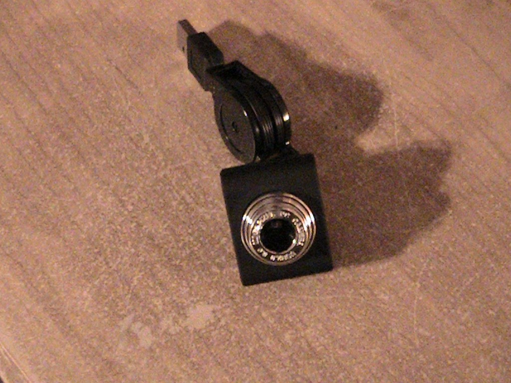
06/26/2017 at 01:34 • 0 commentsInspectorBot will need a forward facing low resolution camera so the user will be able to drive the robot when the robot is in an area such as crawl spaces where the user cannot see the robot. I found a cheap mini USB camera on ebay. Below is the camera.
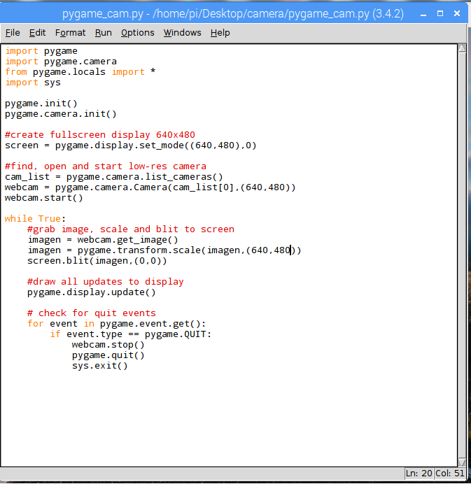
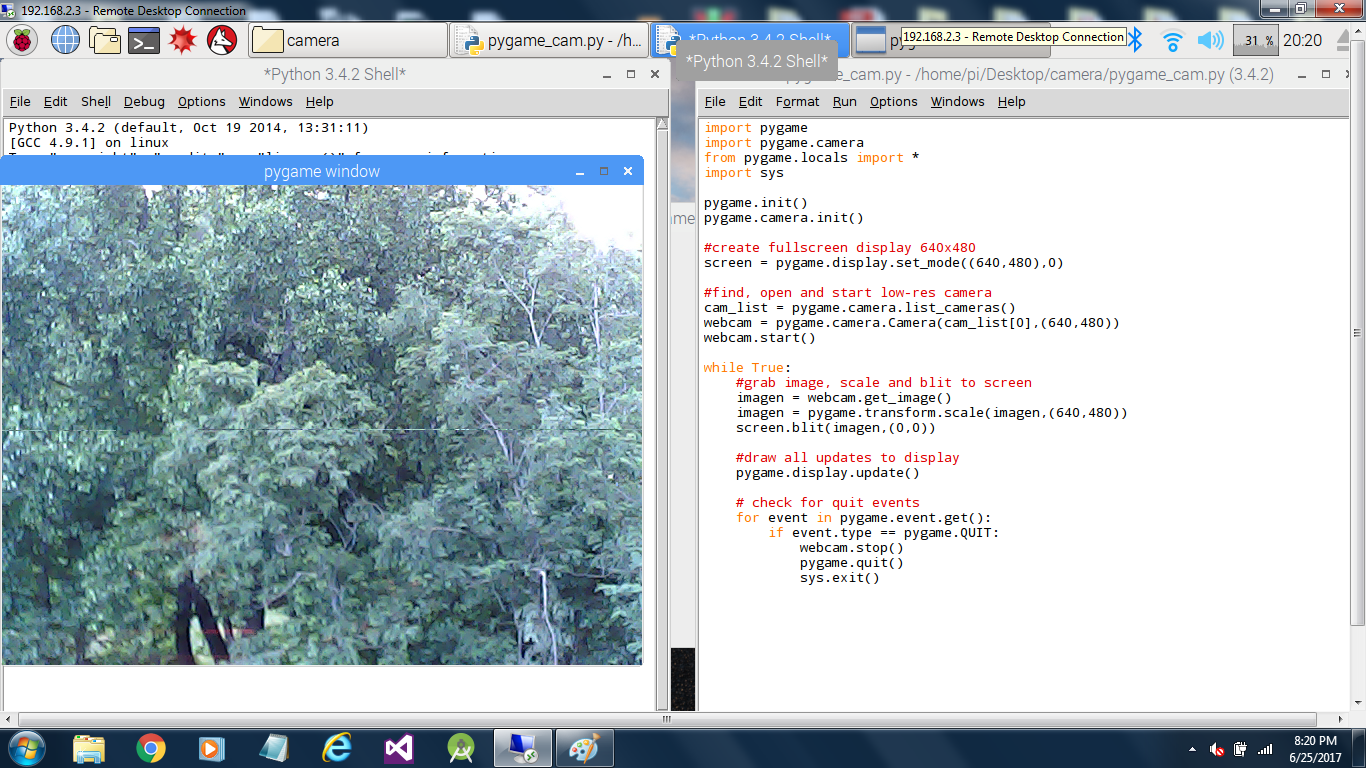
I wasn’t sure if the camera would work with a Raspberry PI so I wrote a short program using Pygame to test it. Below is the program and an image of the program running with the mini camera plugged into one of the Raspberry PIs USB ports. It works well with a Raspberry PI.
![]()
![]()
InspectorBot
An open source robot to inspect under vehicles, crawl spaces and any other dark dirty space you need to take a look at.
 Dennis

 I wasn’t sure if the camera would work with a Raspberry PI
so I wrote a short program using Pygame to test it. Below is the program and an
image of the program running with the mini camera plugged into one of the
Raspberry PIs USB ports. It works well with a Raspberry PI.
