Close
0%
0%

ATtiny45 EverLED

ATtiny45-based Ripoff of Ted Yapo's TritiLED

Similar projects worth following
I bump around in the dark. Putting a lighted beacon on the corners of things would help.

Ted Yapo made these great TritiLEDs.

I didn't have any of his parts, but I thought I'd try anyway. Result? A pretty dark LED that uses only 10 uA of current, including the ATtiny45. That's 2 years+ on a coin cell. Success!

Check out the TritiLED project. It's an inspiring feat of over-engineering. Among other things, it prompted Ted to build an automated LED brightness-measurement rig to calculate the optimal current to drive the LEDs.

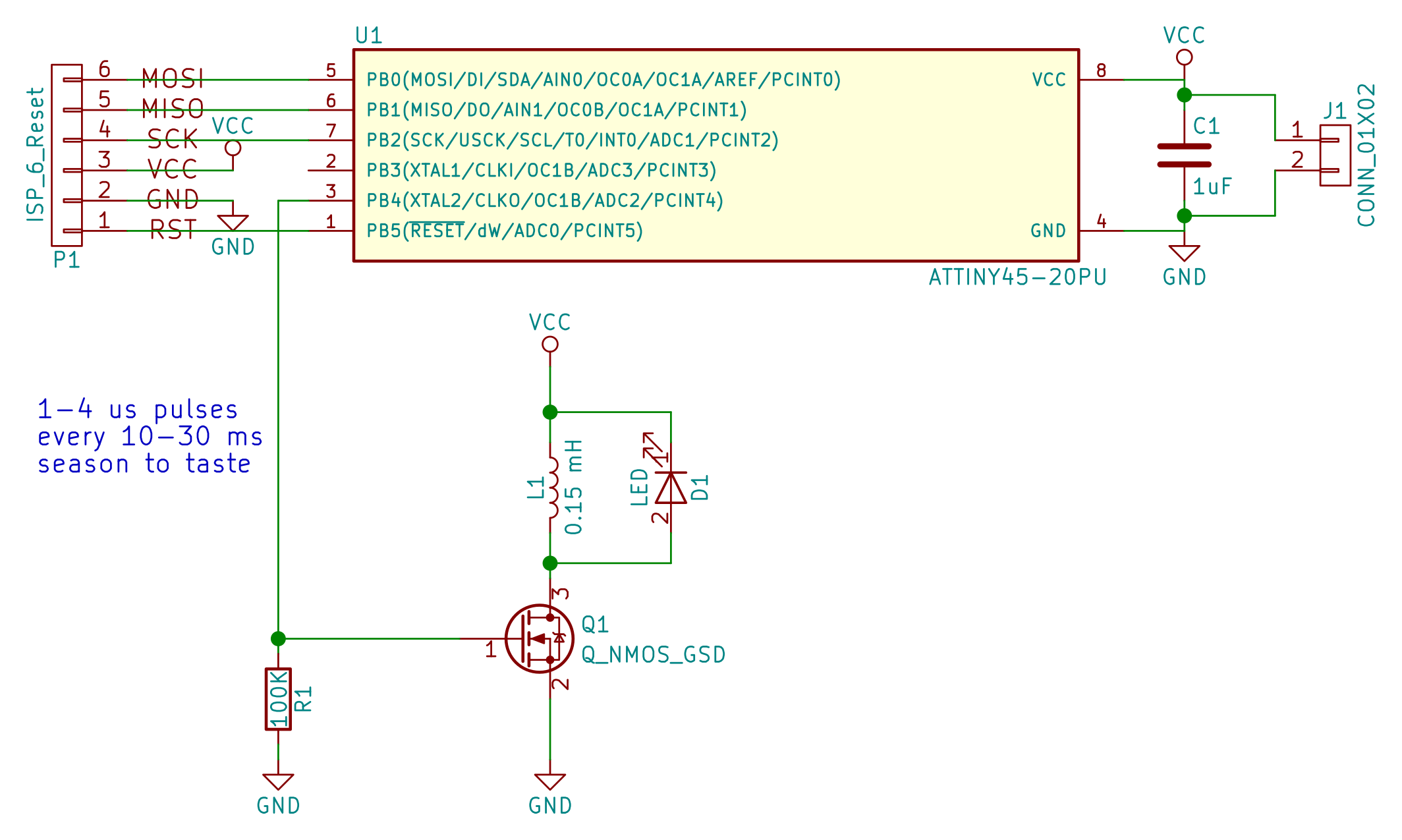
Now here's my take using whatever was on hand: an "ultra" brightness amber LED, a 0.15 mH low resistance inductor, a small logic MOSFET, an ATtiny45, and a capacitor on the power rail.

Same topology as Ted's design: the FET pulls the inductor down to ground, and the LED is wired across it, where you'd normally put a flyback diode.

I'm pulsing on for around 1 microsecond, on-off with no delay for a 1 MHz AVR. The pulse rate is once every ~16 milliseconds, because that's the default value for the watchdog timer.

For details, see the code (in a Gist) or read on.

  • PCBs and Code on the GitHubs

    Elliot Williams06/26/2017 at 21:00 0 comments

    I've had a good time playing around with LEDs. I've even made up a couple of experimental PCBs. And now I've dumped it all to the EverLED project's GitHub.

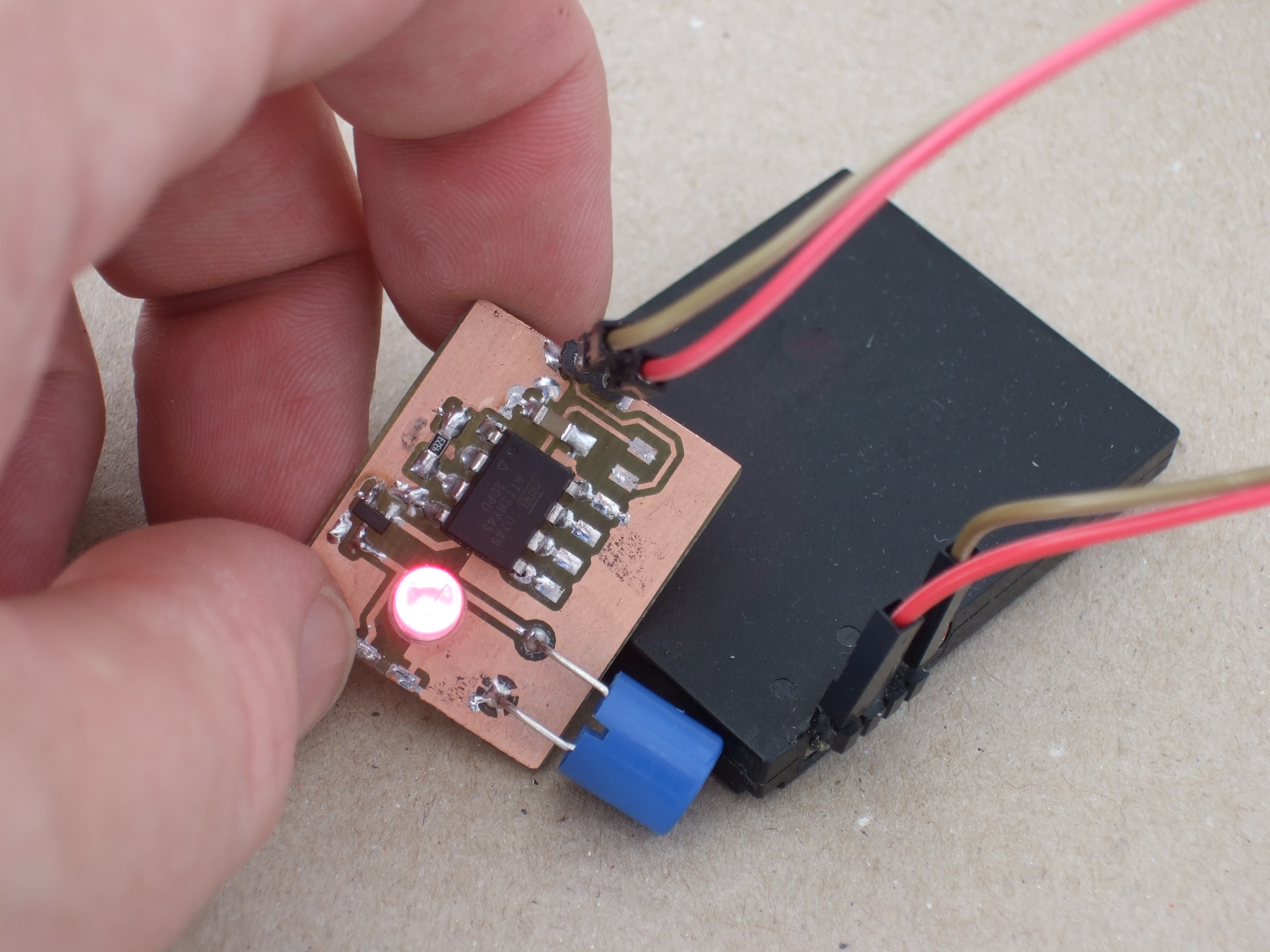
    The PCB has an inline ISP programming "port" that I use sometimes: Reset, GND, VCC, SCK, MISO, MOSI from top to bottom. It's easier to route into a one-sided design than the 2x3 standard configuration. You might want an adapter, or to change the PCB yourself. :)

    If not, there's a PDF suitable for laser-printer toner-transferring (it's mirrored already) and there's a .hex file suitable for flashing.

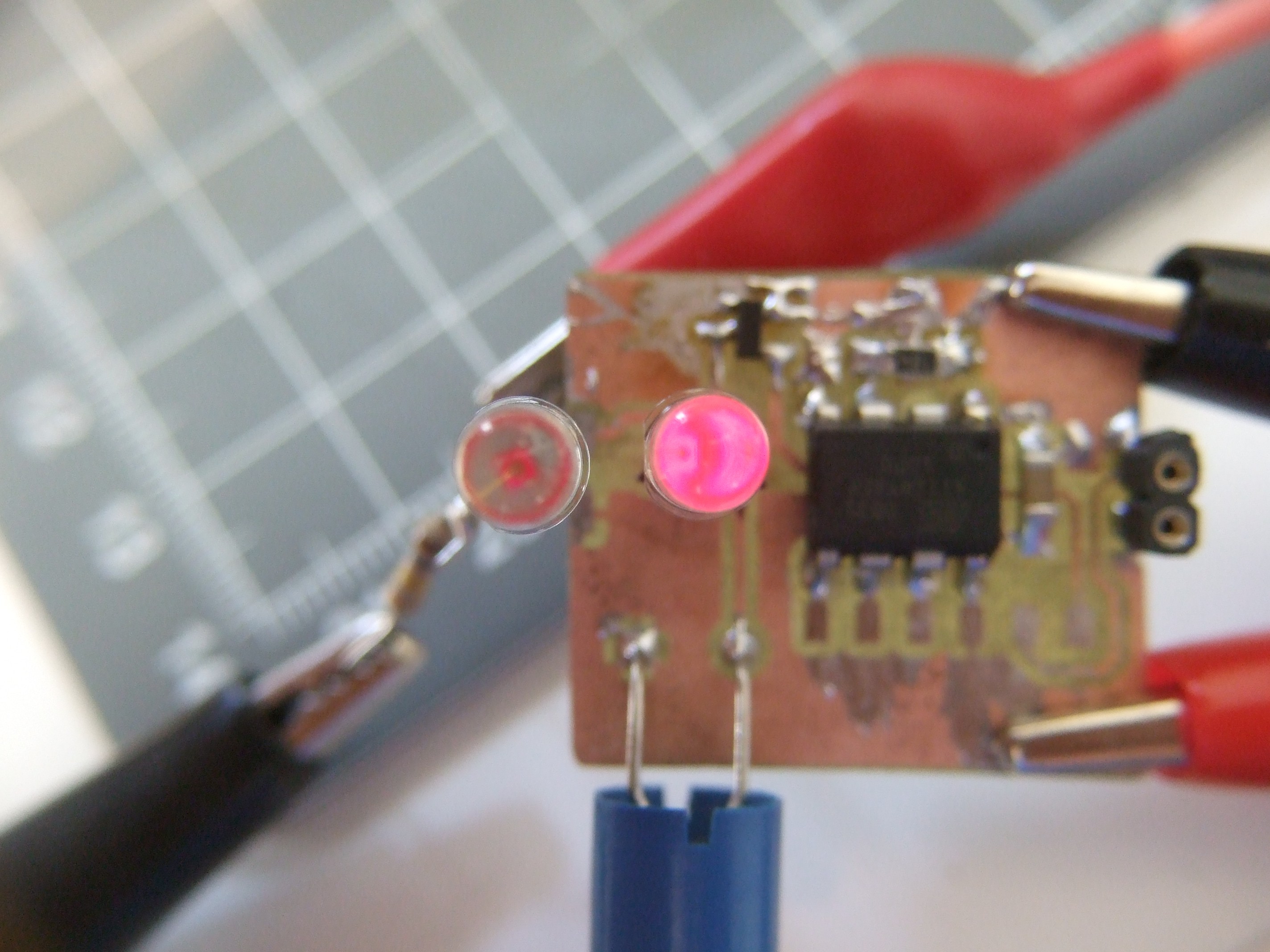
    Thumb and fingers for scale.

    The ultra-bright red LED shown here is pretty bright when looking directly at it, but almost invisible from the sides. I'm cheating here and pointing it at the camera -- it's a lot dimmer when it's diffused.

    Needless to say, the 900 mAh LiIon battery show here is just for testing. In theory, that's 10 years' worth of dim LED. In practice, self-discharge and sheer boredom will dominate, and something smaller makes more sense.

    What's next? With an application that only needs 10's of microamps, it makes power harvesting look interesting. I'll probably also make a small, finished version of the PCB, with a SMD ATtiny and everything compacted up. Or maybe a pushbutton...

    But if you're interested in playing along, go to it! Everything in the GitHub is tested and works for me. Let me know if it doesn't work for you.

  • Current and Inductors

    Elliot Williams06/26/2017 at 13:31 0 comments

    Built a couple more of these over the weekend, and even whipped up a quick and dirty PCB. I'm thinking of pouring something permanent and waterproof around them, like clear epoxy resin for fiberglass or something, and we'll see if they get the two year's runtime.

    I still hadn't really answered the question of how long a pulse is too long, other than by "feel". So I added a resistor (1,775 ohms -- it was in the box) between the light's ground and "real" ground and scoped out the current flowing through the circuit.

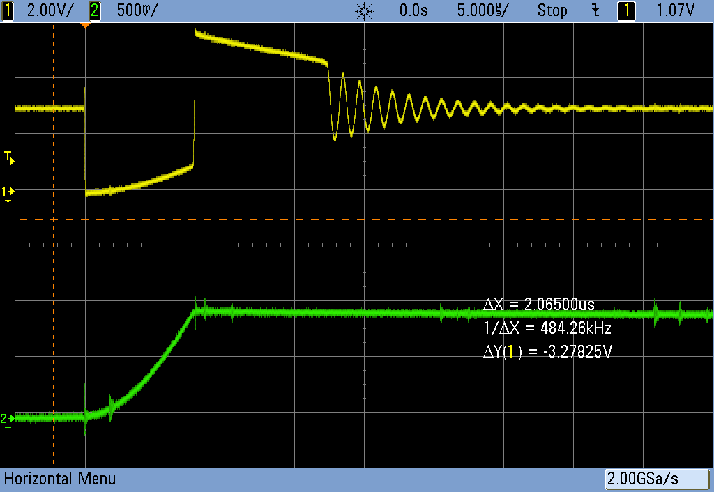
    Running for 8 us, you can see the inductor "charging up" in the green trace, and you can also see the power line starting to sag as the "ground" gets pulled up during the transistor's on time in the top graph.

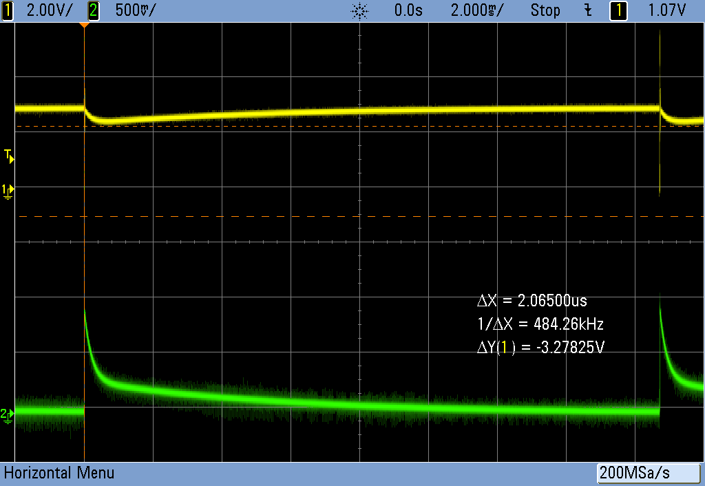
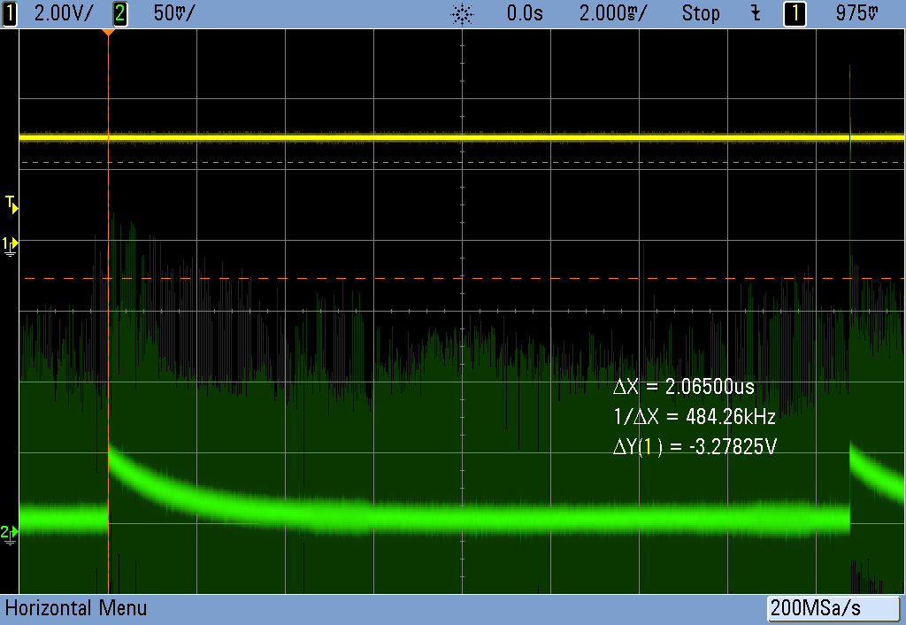
    On a cycle-length timescale, changing the yellow trace to the 3.3 V input supply, you can see it getting pulled down and slowly recovering over time. In current (green), the quick peak is the inductor loading up, and the rest is the on-board decoupling capacitor re-charging.

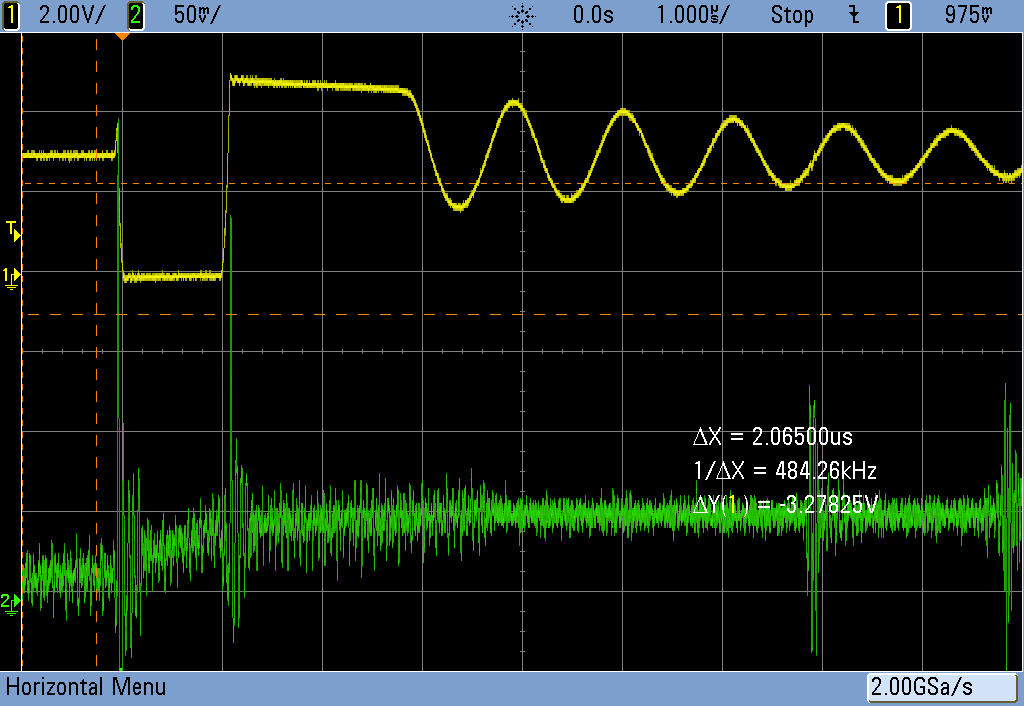
    Meanwhile, with 1 us pulses, everything is basically well-behaved again. The current just begins to ramp up before it gets turned back off, storing a relatively small amount of energy, but also not pulling down hard on the voltage rails -- evidence is the flat bottom to the LED voltage (yellow) curve.

    On this scale, the CPU's spikey power demands are visible, and you can also see that it's nowhere near the "fully loaded" zone. That's where I'm running it, and that's about 10 uA total average current draw.

    On the cycle time scale, you can see that the voltage rail (here in yellow) doesn't really sag all that much, and that the buffer/decoupling cap on the board charges back up to nominal fairly quickly, leaving only the small, constant draw from the microcontroller.

    The conclusion? With these inductors (labelled 0.1 mH) something in the 1-3 microsecond range looks about "right" and drives nearly any LED dimly, with a current consumption of 10-15 uA. I guess I knew this before, but it's reassuring to see measurement match intuition.

    Think of the inductor in this circuit as a time-dependent resistor. When you pulse on, it has maximum "resistance", and this decreases as it charges up its mag field. So if you use a larger inductor, you can store more energy while still staying in the high-resistance part of the curve, but you'll have to leave the pulse on longer. Or vice-versa: if you want to pass more energy, and don't want to draw excessive current pulses, you'll want a larger inductor.

    Anyway, now I'm probably actually done with this circuit. 10 uA is sufficiently low that it'll run for years on a coin cell, and bright or dim enough with the choice of the right LED. The AVR will run up to 6 V, and doesn't seem to crap out until around 1.2-1.4 V, so power is not a problem. Energy-harvesting, anyone?

    If you mess around with the code and find a modulation mode that you like, let me know in the comments?

    I'll post up my (KiCad) PCB files in a GitHub just for completeness, although there's not that much to these things.

    Enjoy!

  • Schematic

    Elliot Williams06/23/2017 at 21:33 1 comment

    The only interesting part of the project is the FET, inductor, and LED. The rest is just making pulses while using as little power as possible. This is not much of a circuit. Values are what I used, but are probably only really good as a starting point.

    Capacitor on the power rail is very necessary. When you crowbar the power rail through the inductor, it makes a predictable sag. I ran it for a while without, and the chip reset with every pulse. Doh!

    Also necessary is the pulldown on the FET. If it opens for more than a few microseconds, the inductor acts as a short to ground and it gets very hot. In your hand. As you're trying to program the darn thing.

    Anyone wanna bet on how much more/less power a CMOS oscillator and pulse-shaper would use than the AVR?

  • Build First, Think Second

    Elliot Williams06/22/2017 at 20:46 1 comment

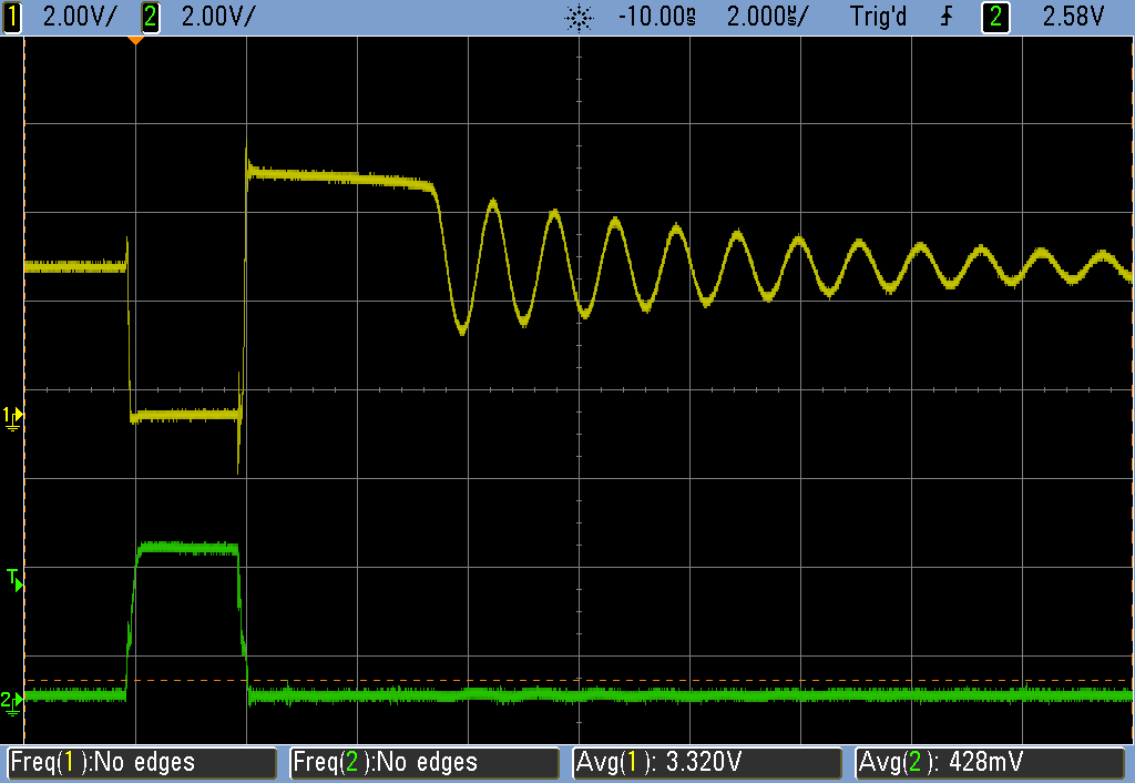
    So here's how this works. The yellow trace is the voltage at the + pin of the LED (the low side of the inductor), and the green is the "one microsecond" pulse from the AVR, that really looks like two microseconds, huh?

    The AVR turns on the MOSFET, dropping the low side of the inductor from 3.3 V (battery voltage) to zero. Current is running through the inductor. The FET turns off, and current wants to keep running through the inductor, building up a voltage until it's high enough (here a ~2 V LED + 3 V battery) to light the LED.

    The LED lights up for about 3.5 usec and then dips under its threshold and does that funny oscillating thing. Would an LED with a lower threshold have smaller amplitude oscillations, and waste less energy? I have no idea how much energy is represented by the wiggles -- my guess is that, with a low-resistance inductor, it's doing very little work = not much.

    The AVR sleeps for 16 milliseconds -- an eternity on this timescale -- and it all repeats.

    For a given inductor/LED, what is the optimal pulse width? What I want, but haven't figured out yet, is to measure the current through the inductor and figure out when it's "full". You can do that empirically by changing the AVR's on-time and noticing how the LED's on time-responds because that corresponds to the energy stored in the inductor's field. Beyond something like 4 microseconds, the on-time doesn't seem to lengthen all that much, so maybe 2 microseconds is a lucky guess.

    I could add in a resistor and measure voltage drop, I suppose.

    Putting two LEDs in series, the max voltage goes up to ~7-8 V, or 3 V + 2x LED threshold voltages.

    If you use a larger inductor but a fixed pulse length, the current draw drops, which makes sense because it "charges up" more slowly -- equivalently it displays more reactance. I'm not sure if I should be thinking in the time or frequency domains here...

  • Wait a Minute!

    Elliot Williams06/22/2017 at 13:37 4 comments

    What the heck am I doing? The whole point of the flyback/inductor trick is to make a step-up voltage converter, and I'm running a 1.8 V LED off of a 3.3 V battery...

    Well, whatever it's doing (providing more reactance?) it's doing a good thing: pulling the inductor out and just driving the LED straight burns 60 microamps. It may also be a fair bit brighter, but that's not really the point of this exercise.

    I called this done, and now I need to play around with the circuit some more. Sigh.

    ---------------

    Edited to include Ted's constant-current comparison: one LED, one datapoint.

    Two LEDs from same tape reel. Left driven at constant 11.1 microamps through a 150k resistor. Right driven by pulse circuit at 9.1 microamps (including the ~5 microamps eaten by the AVR and transistor -- so maybe 4 uA avg for the LED).

    I couldn't even tell that the left LED was on until I cupped my hand around it, as I'm doing in this image. The difference looks about like this to my eyes as well -- they're strikingly different. One is "bright" and the other is barely on.

    As Ted points out, running the LED with milliamp peaks seems to make them run a lot brighter. Woot.

    Neither of these will illuminate anything, mind you. In a dark room, you can see the brighter LED easily, but it's not throwing enough light to read by or anything. Still, if you just want a marker, it's perfect.

  • Quick Test, AVR Power Optimization, Done!

    Elliot Williams06/22/2017 at 10:03 0 comments

    Ted uses a 1 mH inductor, but I only had 0.15 mH. Ted uses a particular high-wattage LED. I had a regular "ultra" amber LED from a surplus store. Ted uses a low-power microcontroller. I had an ATtiny45. Would it blend?

    The first tests were just the pulses, and sure enough the theory works just fine -- super-short pulses "charged up" the inductor and let it dump back through the LED. Alone (with 4 us pulses every 20 microseconds) it was running 4 microamps.

    Adding in the ATtiny45 with busy-wait loops and no power optimization used up ~500 microamps. Well, that won't work.

    Best thing to do? Turn off everything possible -- power_all_disable() from avr/power.h -- and put the pin-toggling code into an interrupt that fires off the watchdog timer. That way the ATTiny45 is sleeping in full power-down mode for 99.99375% of the time. Not a low-power chip when it's on, but who cares?

    I also shortened the pulse duration down to ~1 microsecond, because it still looked bright enough to see at night, and I couldn't go any faster.

    Et voila! 10 microamps (9.9, but who's counting?) running. Or about 2.5 years on a coin cell, nominally.

    Could it be brighter? I presume so. Ted's research on optimal LED drive currents would be the place to go. Or I could just use longer pulses, which seem to do the trick.

    Could it use less power? Maybe. I didn't particularly optimize the size of the inductor.

    The FET (IRLML 6244) is pretty good for the application. Turns on and off quick at 3 V, has low on resistance. I don't think that could be significantly improved on.

    And that's it. It's not refined like Ted's, but I built it and it works. I'll might play around with different LEDs or inductors, but maybe later. Right now, I just want you to know that although one can polish a simple design like this until it shines, it also works well enough with whatever you've got on hand.

View all 6 project logs

Enjoy this project?

Share

Discussions

MarkRD wrote 07/06/2017 at 04:15 point

If you need to stick with AVRs, you could actually get better performance out of an ATmega328P. Stick with me here, I'm not crazy.

You already know that your microcontroller is sucking up half the current. That's because the watchdog timer uses about 4 uA nominal at 3V room temperature. The bare sleep mode itself is only about 100 nA. Slowing down the interrupt rate won't work since the watchdog timer remains running during all that time and uses the same power.

The ATmega328P has additional power reduction modes, the important one here being Power-save. This mode keeps Timer2 running if it is set up in asynchronous mode. Slap a 32 kHz watch crystal on the crystal pins, and Power-save mode uses a nominal 600 nA, nearly 10x less than the watchdog timer. You can use that timer to generate your wakeup interrupt.

I don't know of any ATtinys that have a Power-save mode. You can always look.

  Are you sure? yes | no

PointyOintment wrote 07/30/2018 at 19:50 point

And if it doesn't need to be an AVR (and you can program an 8051), I'd consider Silicon Labs's C8051F9xx: https://www.silabs.com/documents/public/application-notes/AN358.pdf

Active current consumption down to around 80–90 µA at 32.768 kHz, and sleep down to 300 nA with the RTC active (or even 10 nA in applications that don't need RTC or BOD). A disadvantage is that the supply voltage range (0.9–3.6 V) doesn't go as high as the AVRs', and is split into two modes due to the need for boosting below 1.8 V (and I don't know if you can switch between the modes on the fly).

With these, it seems that if you have the WDT (which is actually part of the Programmable Counter/Timer Array (PCA), which isn't discussed in the app note*) active, you might as well have the RTC active too, because you'll need the low-frequency oscillator, which belongs to the RTC. Then you can use the time from the RTC to modulate the LED brightness to communicate the time, and you could even use the internal temperature sensor to compensate the RTC (if it doesn't do so automatically). I'm thinking that once every N wakeups (calculated to occur once per minute, I guess), it takes the time from the RTC, processes it into a time series of brightnesses, and stores that in ram (which persists through sleep). Then, on subsequent wakeups, it reads the next value in the series (using a counter) and uses that to modulate the LED brightness on that pulse. This will of course consume more power than not doing it, but I think it'll still consume much less than the ATtiny not doing it.

*Therefore, I don't actually know its power consumption, so this could be a bad idea…

(I just happened to know about this series of microcontrollers because I was looking for a microcontroller with the lowest available input voltage a while ago, for a project I never actually started—a solar garden lamp that would blink the temperature and humidity in Morse code.)

  Are you sure? yes | no

[deleted]

[this comment has been deleted]

MarkRD wrote 07/08/2017 at 00:41 point

10 nF is pretty small, putting well under a milliamp average through the LED. If they're cheap garbage LEDs I'm not surprised it wouldn't be bright. Use a higher-efficiency LED and a higher value capacitor and you'll be able to easily blind yourself.

I have a nightlight that uses an 820 nF capacitor and is plenty bright off half-wave rectified 120V 60 Hz AC.

  Are you sure? yes | no

Daniel wrote 06/27/2017 at 13:21 point

Love it. Who's up for the logical next step of trying to do the same with a 32-bit ARM processor?

  Are you sure? yes | no

Mike Szczys wrote 06/26/2017 at 19:32 point

Energy harvesting indeed. My cyber-punk mind has a vision of futuristic lamplighters -- the people who used to go around at dusk and light the gas or oil streetlamps -- who will carry around an induction coil on a long pole and recharge the supercaps on all the streetlights once a week or so.

You certainly seem to be into super-cap territory with this build. I'd love to see that whipped up with a handheld portable contact-less recharge system.

  Are you sure? yes | no

Elliot Williams wrote 06/27/2017 at 15:21 point

I like the wireless charging idea!  That's awesome.  I'm actually going to shoot for just leaching off the mains voltage, if it's possible. Or maybe solar cells, and I'll walk around with a big flashlight.  :)

As for super-caps: <cylon voice>By your command.</cylon voice>


Left is 3 V, 0.6 F polyacene cells from <a href="http://www.goldmine-elec-products.com/prodinfo.asp?number=G20754A">electronic goldmine</a> about ten years ago when they were on sale for 100 for $10.  3 x 0.6 F = 1.8 F?  On the right, 5 V, 1 F supercap.  

Both charged up to 5 V a few minutes ago. Fight!  

  Are you sure? yes | no

Mike Szczys wrote 06/27/2017 at 15:27 point

Love it!

Thinking of mains harvesting... spec'ing the optimal coil feels like black magic to me. I'd love to see how you take that on!

  Are you sure? yes | no

electrobob wrote 06/22/2017 at 22:30 point

Cool! Never thought about walls :)

I am doing a similar thing to find remotes for my IOT stuff, only using a charge pump instead, to double the voltage from 2AAA or coin cell. 

It seems it is super easy to get white LEDs (requiring close to 3V) to be visible at 10uA, but good luck with red or green., noting in my collection is even remotely visible. 

  Are you sure? yes | no

Elliot Williams wrote 06/23/2017 at 20:31 point

Yeah.  It's worse. :) The micro is eating up 5-6 uA, so the LED is only seeing 5 or so, depending on how you run it.  I might try Ted's trick of slowing down the interrupt rate and double-pulsing to get the AVR's share down.  

LEDs that have worked: "high efficiency" yellow, amber, and red.  A warm white ~9V 10 W chip-on-die put out a shocking amount of light on the same current, but it's a $5 LED for a $2 project.

My guess is that those little 1/2 W white square dealies would be great too.  (Get ~10-20 out of a broken LED lightbulb.)  Our IKEA Dioder light strip glows very faintly when unplugged (!) just on picking up radiated mains.   This would be an awesome intentional energy harvesting project.

LEDs that have failed: garden-variety indicator red and a 0603 green.  (Out of the LED box.)  I haven't tried too many unlikely ones, because I'm aiming for efficiency anyway, right?

What's really fun about this circuit?  The power / current is independent of the LED because you're "charging" up the inductor a fixed amount of time, and it just dumps whatever it's got into the diode.  I noticed this while swapping out LEDs -- same current, just different apparent brightnesses.

  Are you sure? yes | no

electrobob wrote 06/24/2017 at 21:56 point

Indeed, i tried a 5W RGB LED and the color ones from there are much brighter at small current. 

You could of, course cheat by using 2 cells. Around here you can buy a set of white and red bike lights for 3 euro. Each has 2 2032 batteries inside and a circuit to switch them off/on/blink. 

There is not much you can do about the ATTiny, the wdt does burn a lot. MSP430?

  Are you sure? yes | no

Similar Projects

Does this project spark your interest?

Become a member to follow this project and never miss any updates