-
MORPH base testdrive
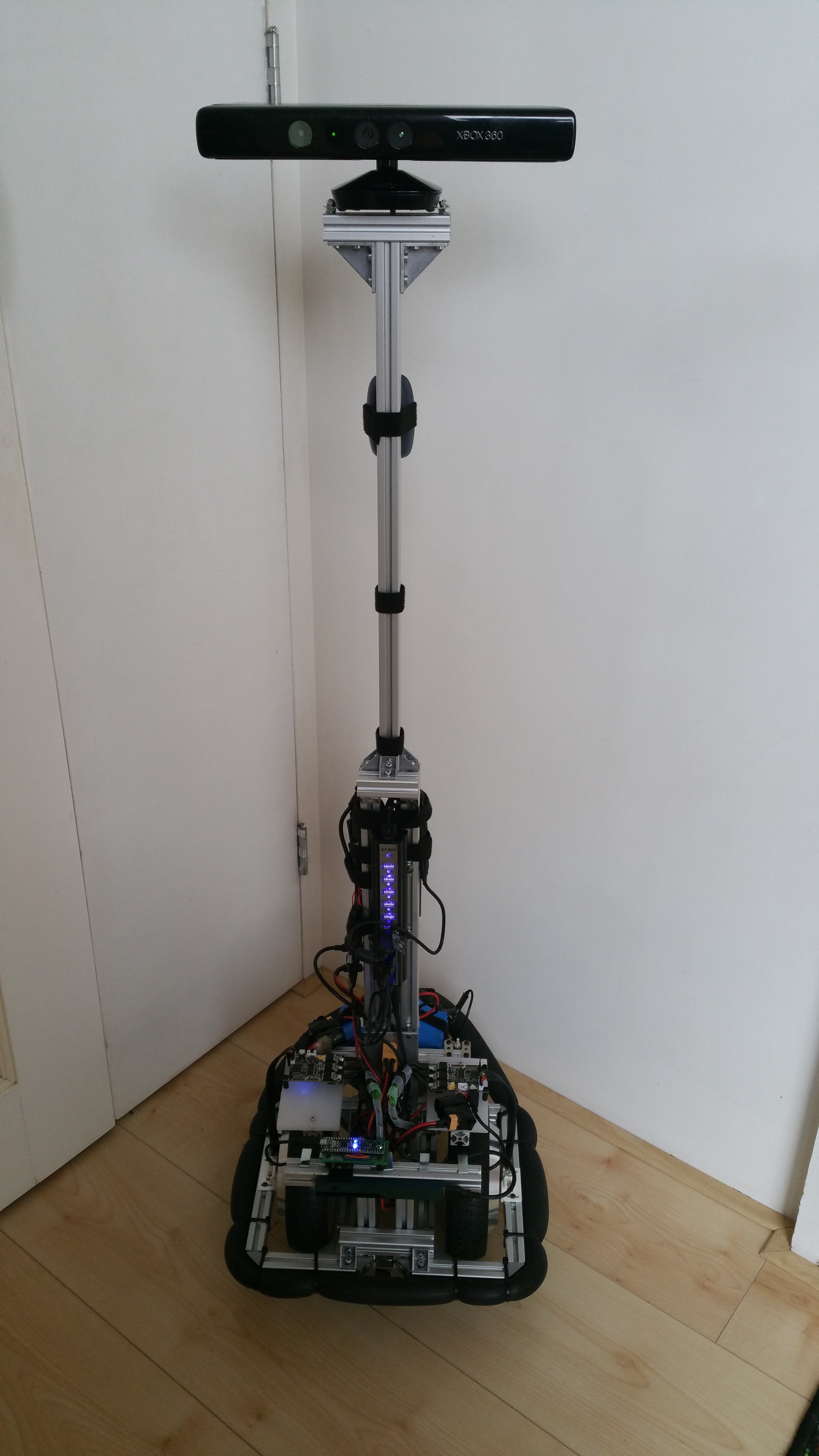
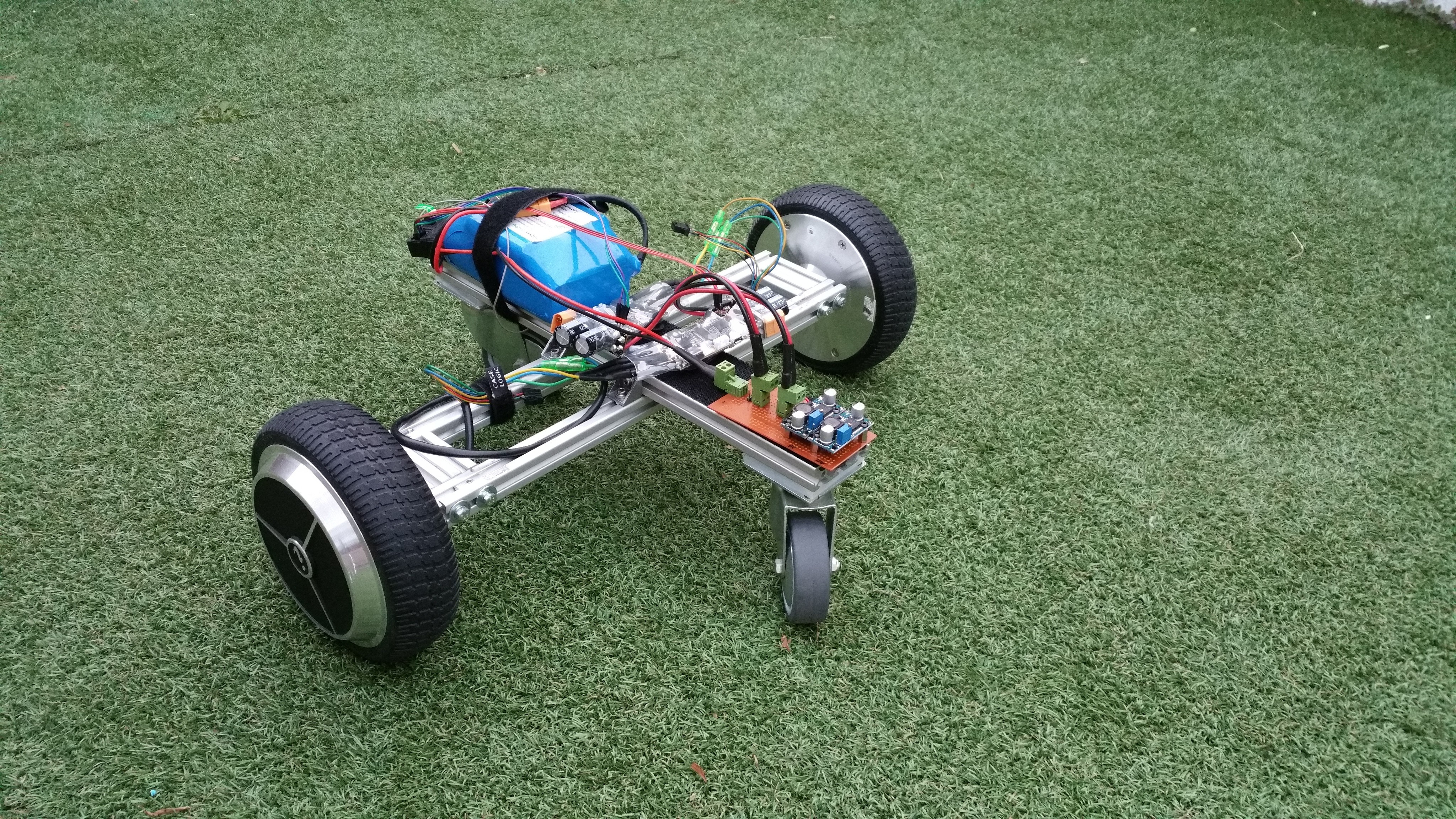
10/15/2017 at 20:33 • 0 comments---------- more ----------After working at some other projects at home I finally had some time to resume work on this project. As the video shows, the base is functional (but still teleoperated).

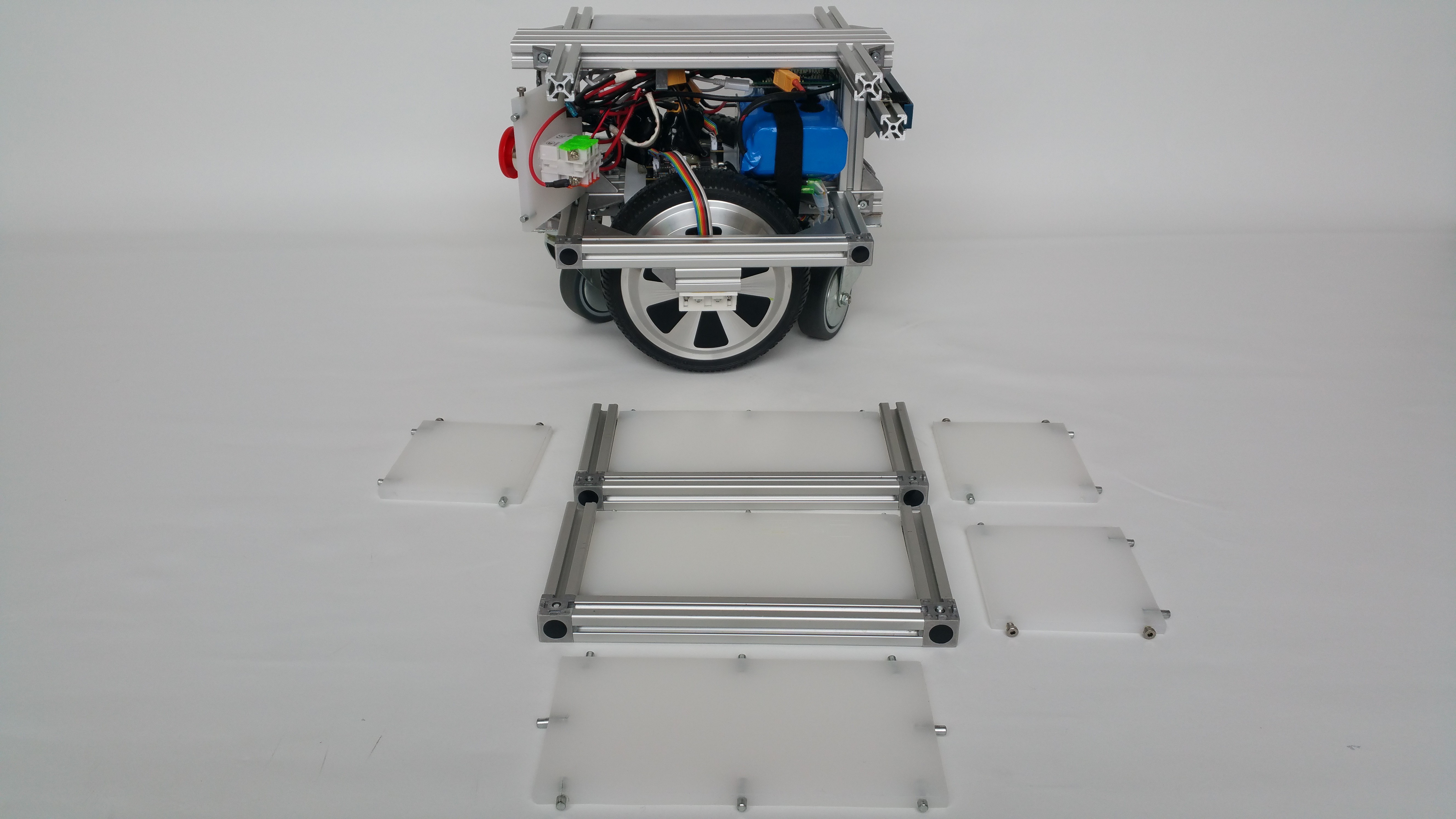
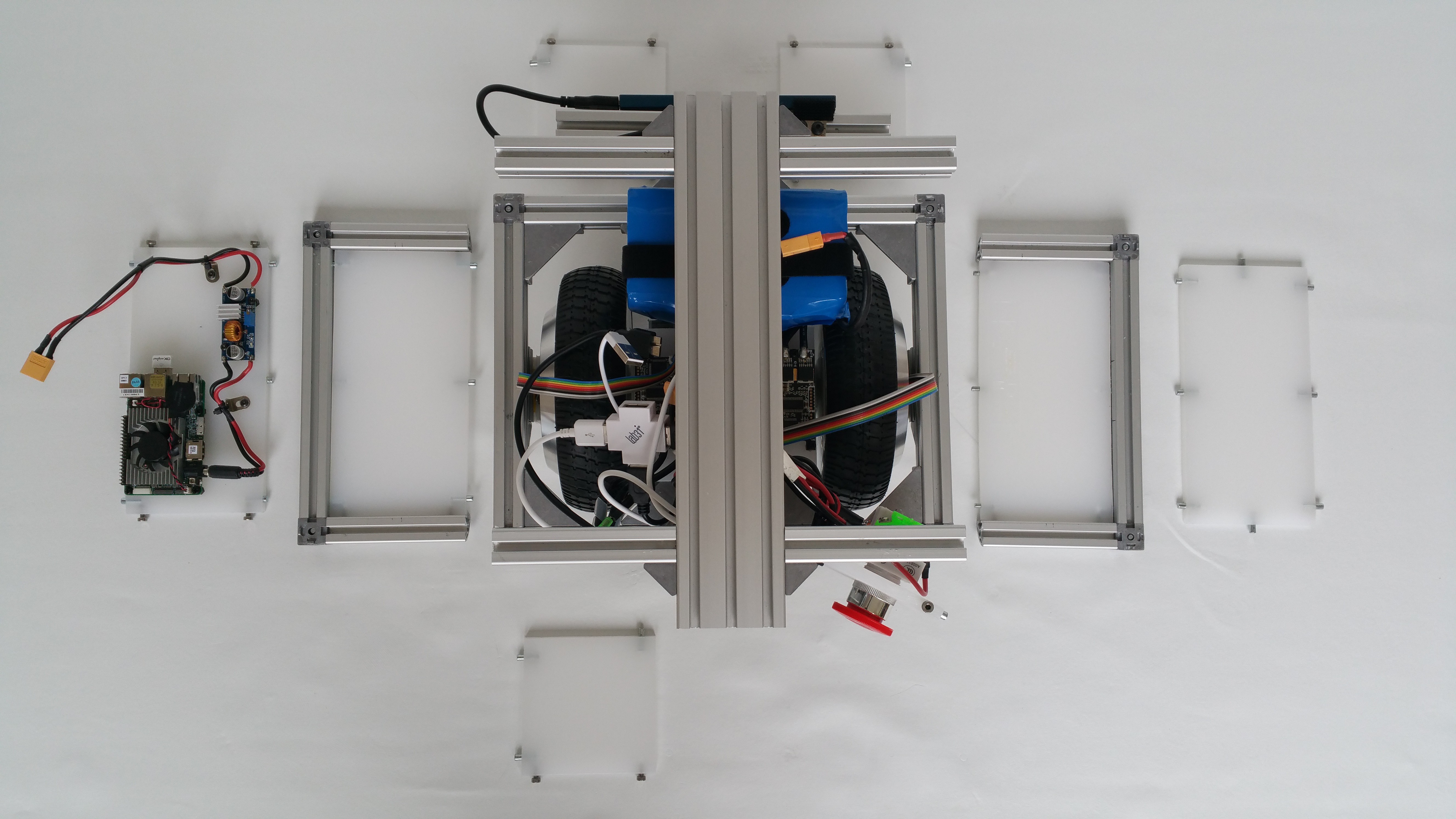
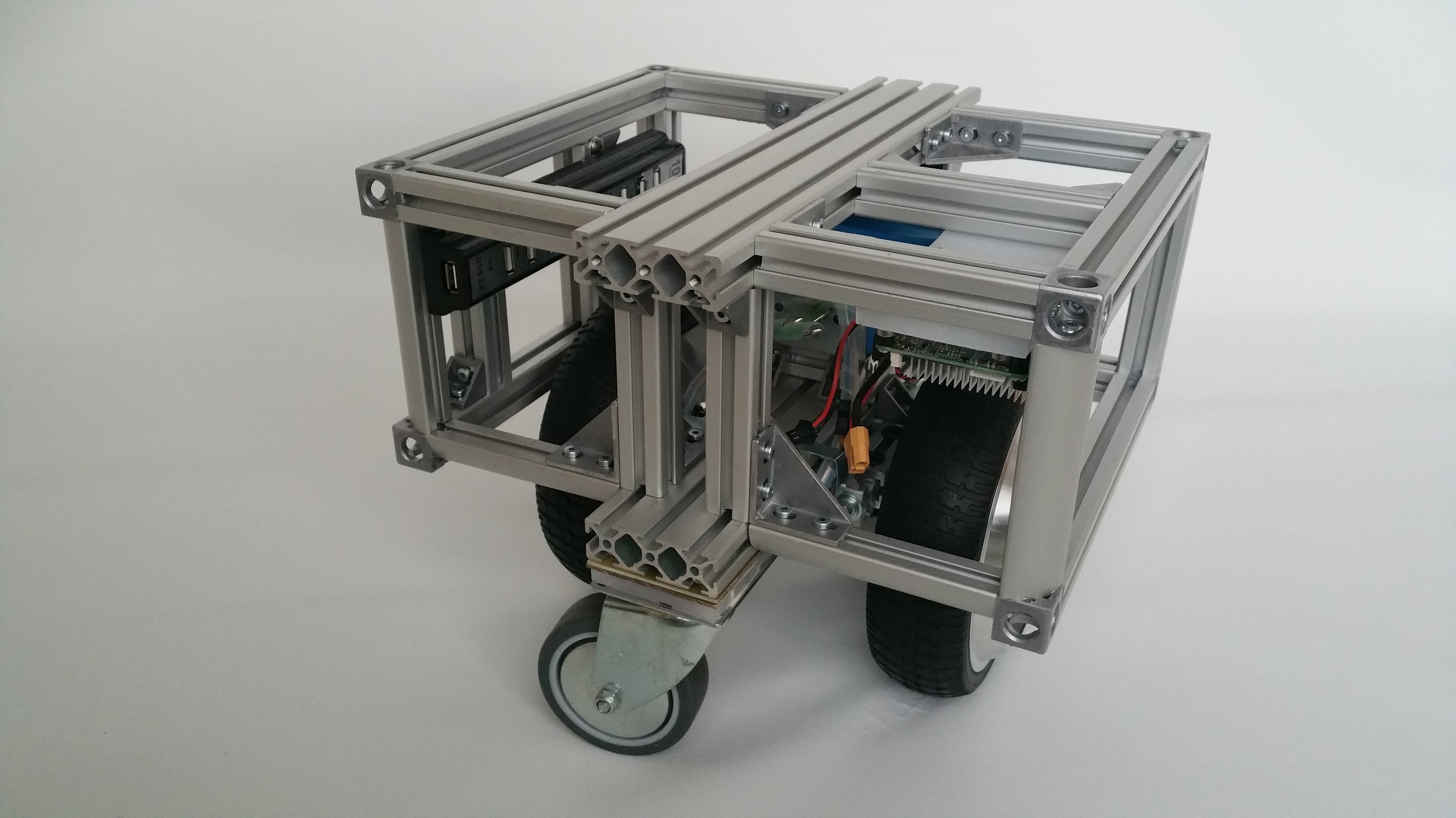
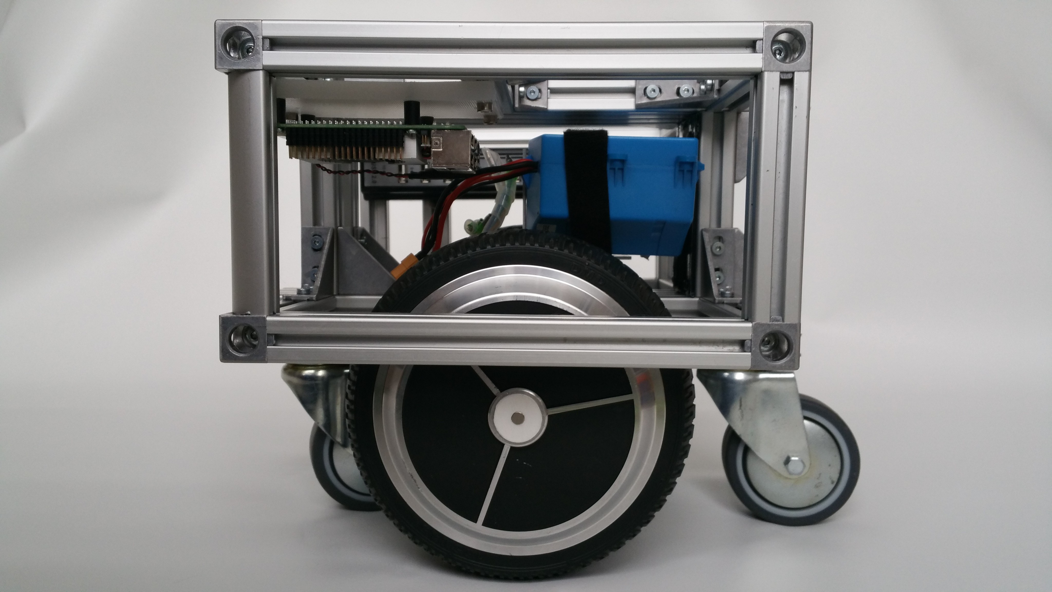
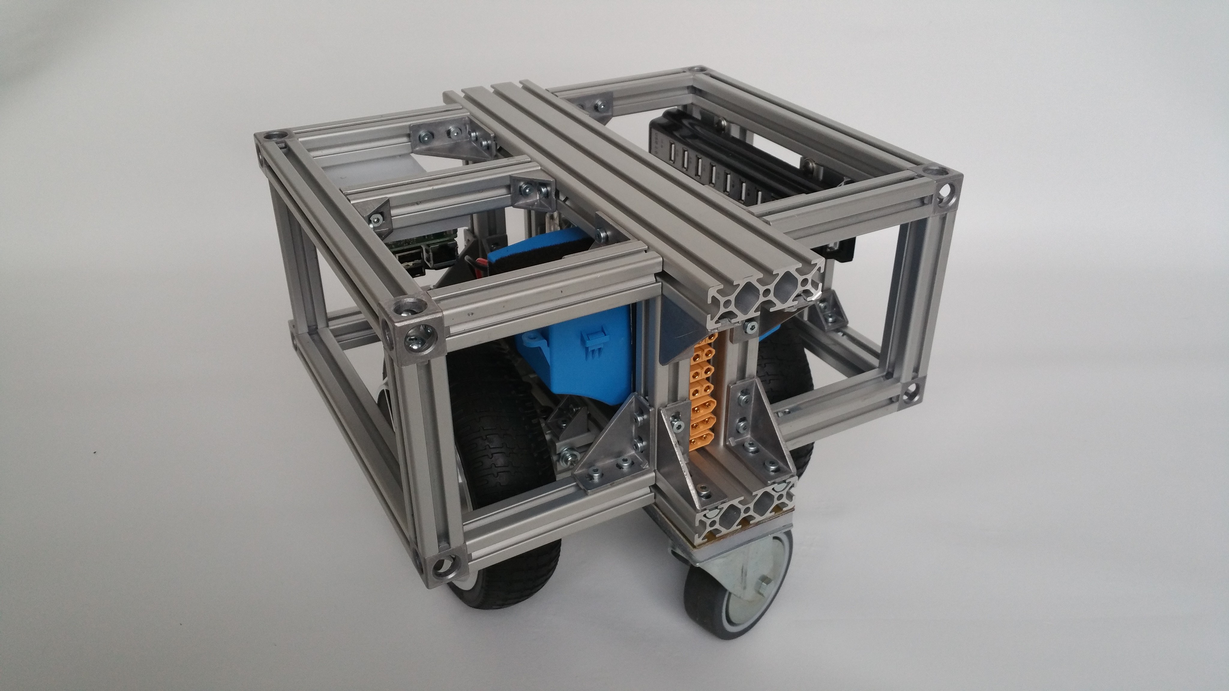
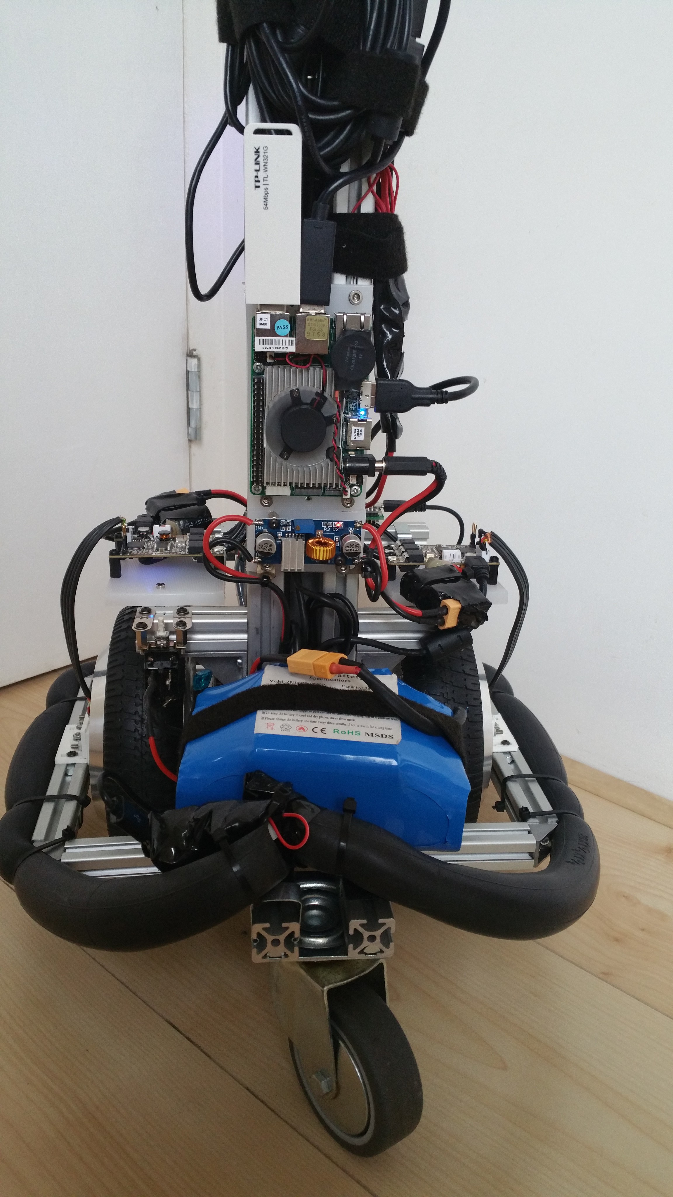
The left and right side panels can be removed by unscrewing the side top two bolts and bottom two bolts with an allen key. I drilled holes in the cube connector covers which allows unscrewing but keeps the bolts in the cube connector so they don't get lost. Also this makes it easy to recognize which bolts to unscrew. By using this configuration the bottom T-slot bar always stays fixed to the robot and the wheel sensor with it. This prevents recalibration each time.
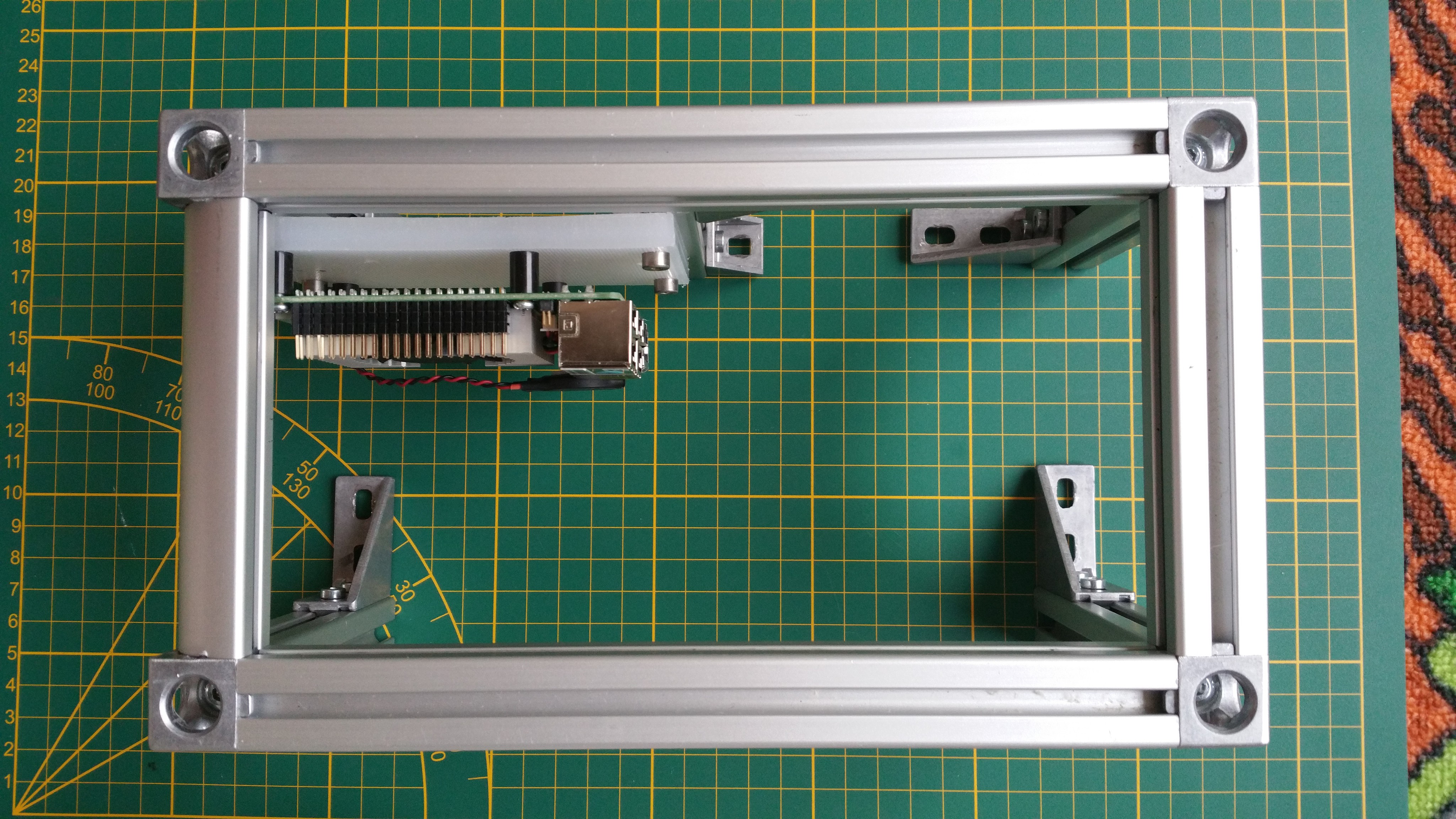
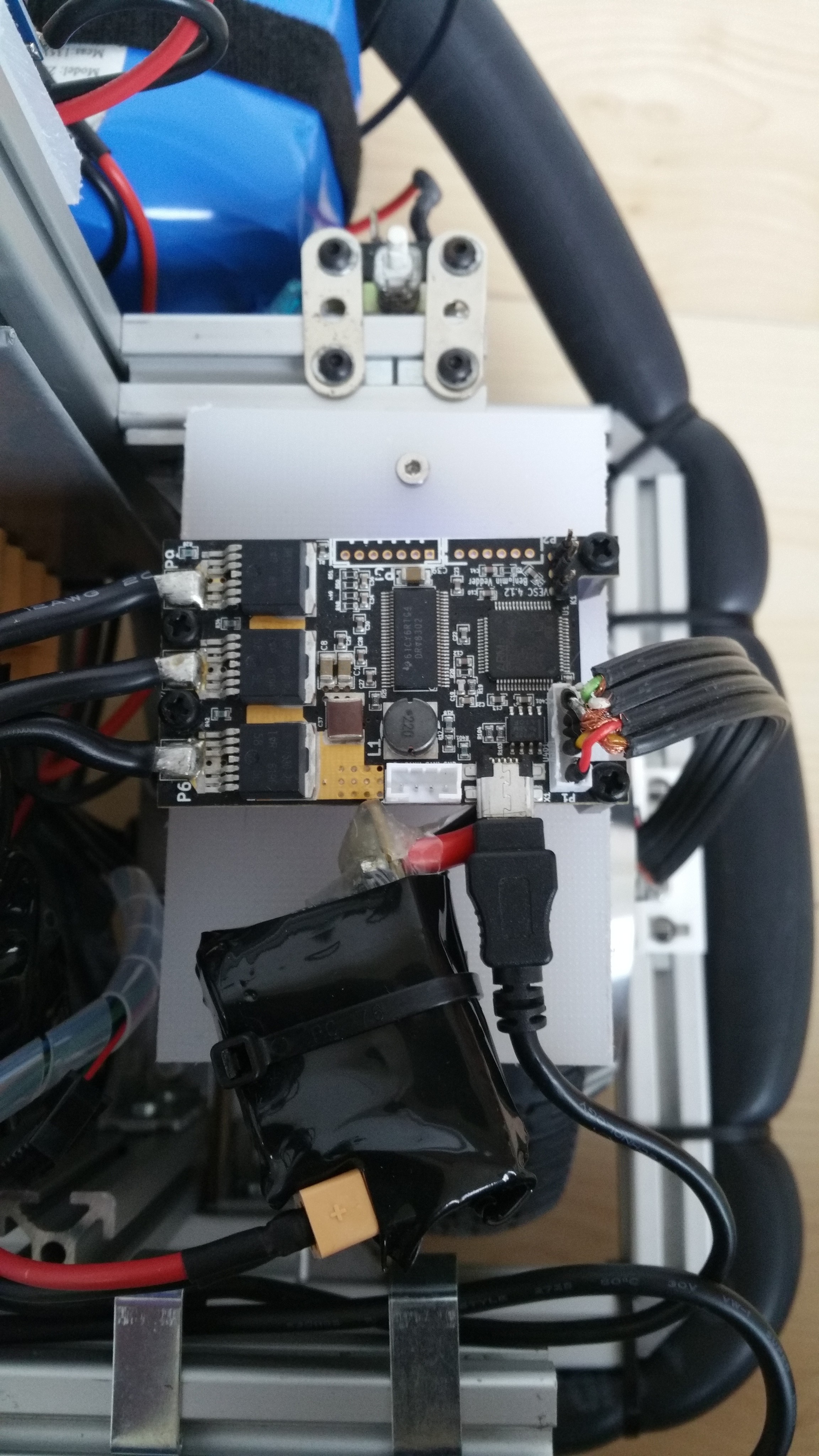
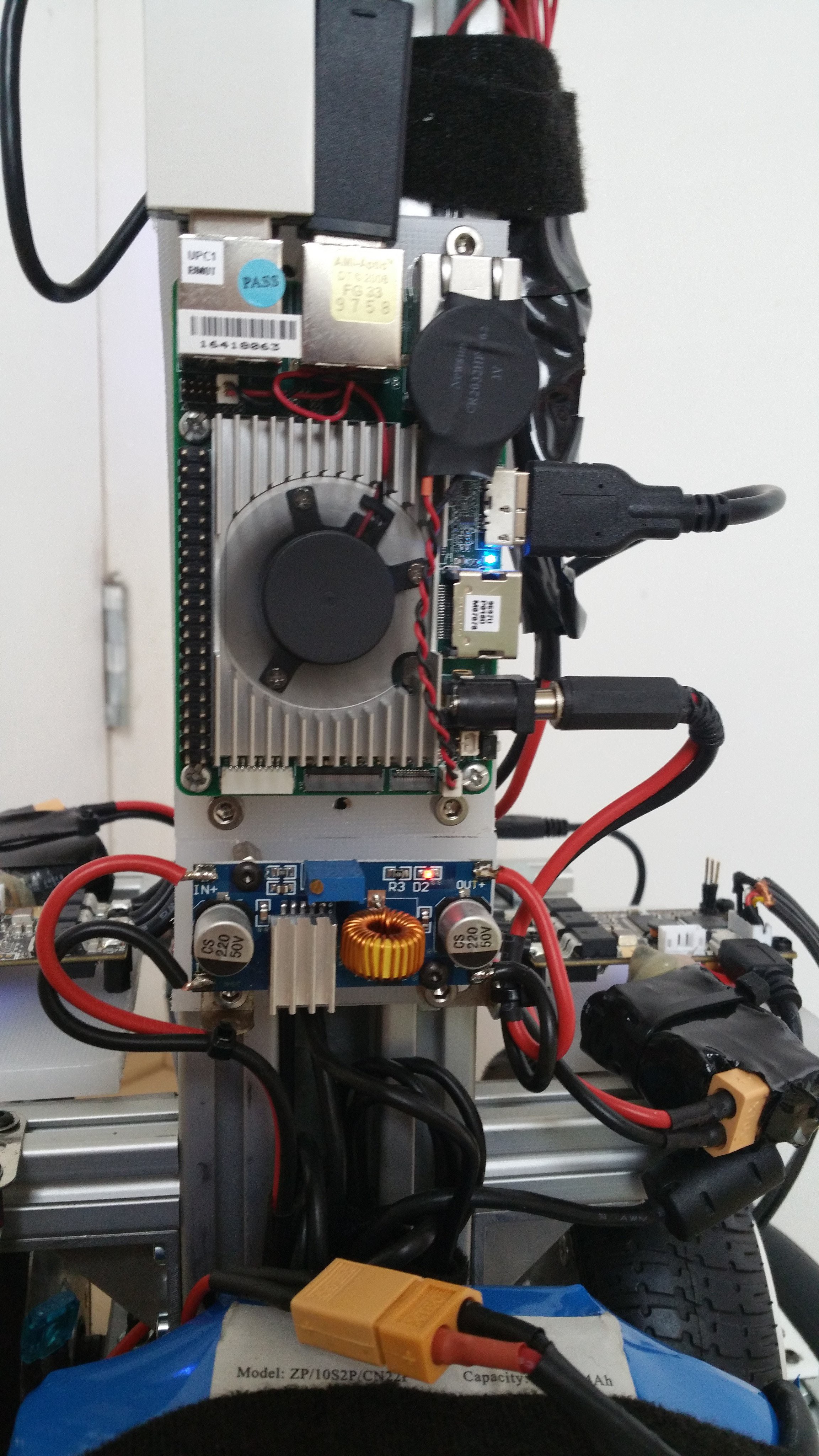
After removing the main side panels other panels can be removed without tools. Each small side panel can rotate out or taken out completely. The two VESC's are mounted on a polyethelene board in the center together with the battery and power distribution board. The computer (Up board) is mounted on one of the top boards, together with its DC-DC converter.
I used a smaller 4 port hub this time, because the space was too limited for the 10 port hub I used before. I figured it would make more sense to go with distributed hubs for the top of the robot anyway, instead of routing all cables to the base.One of the small sidepanels provide a emergency stop, charge connector and power switch for the computer.

Next step is mapping and autonomous navigation. For this to work I will need to update the robot description (urdf) and implement sensor fusion for the gyro and odometry using the robot_localization package. Then I can attempt to build a map using gmapping.
-
Panels
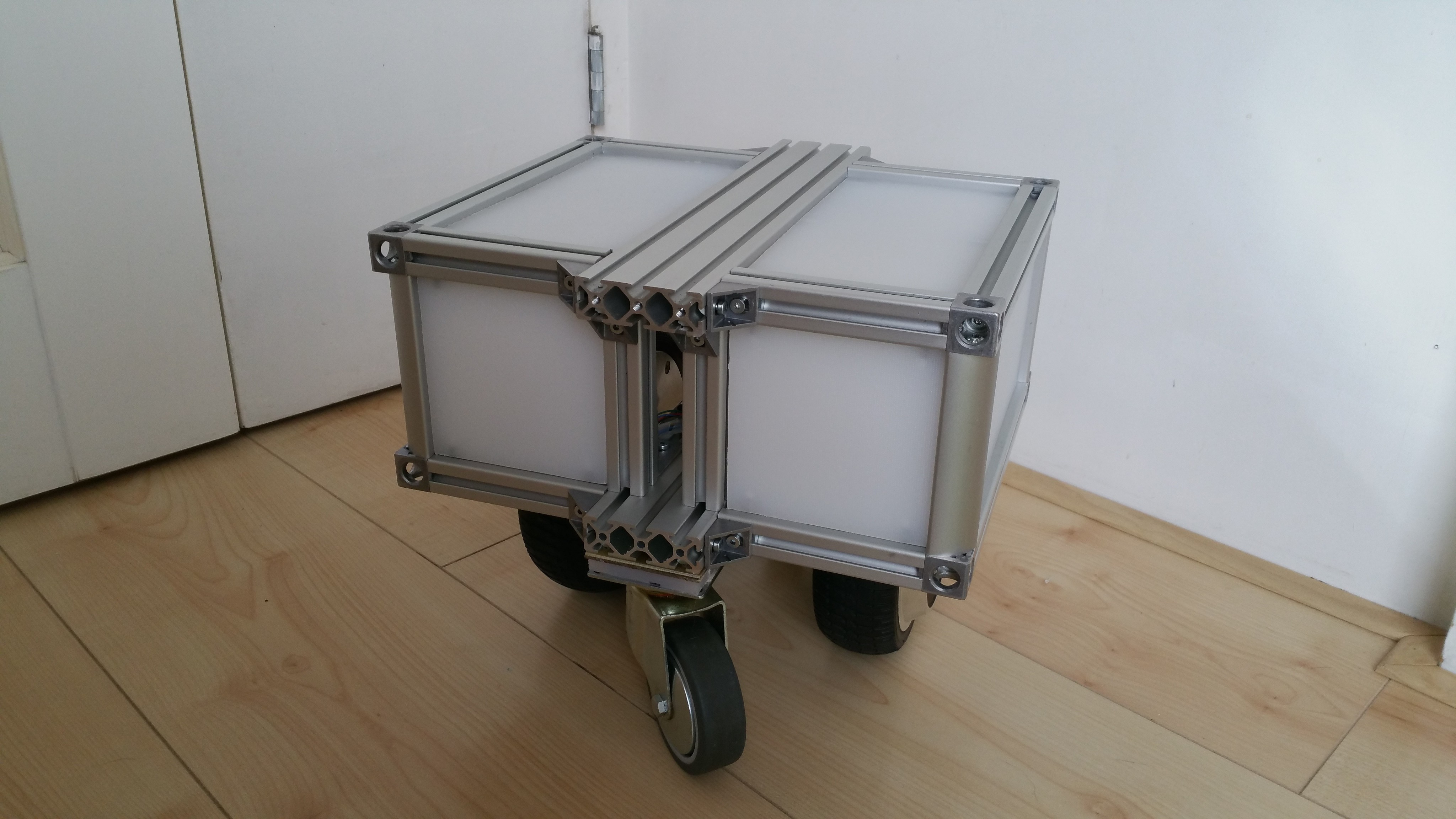
07/28/2017 at 08:42 • 0 commentsThis is just a short update to show the result of added panels. I removed the additional supporting beams which were used to mount the USB hub and Up board. Instead these will be mounted on the panels saving some space. Although the idea is to add a fleece skin to the robot, the panels provide protection for the electronics and make for a more generic base.
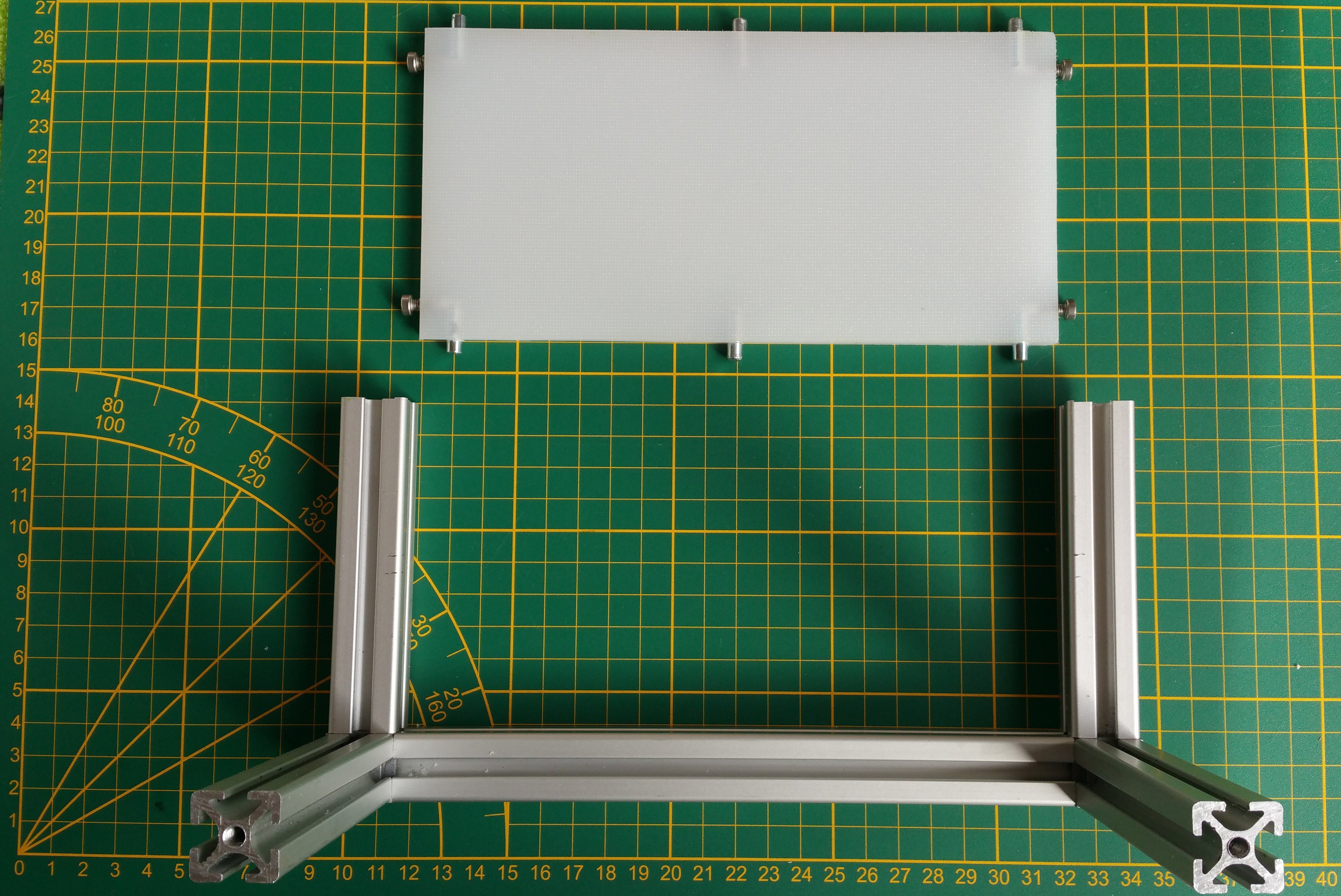
The panels are made from the same 8mm polyethylene as used before (a.k.a. Ikea chopping board). The panels slide in the slots with M4 bolts. The other sides have 5mm rods which provide additional support.
-
Design #5: Stronger enclosed base
07/24/2017 at 08:35 • 1 commentAt this point I had a design that worked pretty well. But still there were things I wanted to improve:
- change the frame to be able to carry a load
- protect the electronics
- change to a more generic mobile base
- improve the caster wheels ground clearance
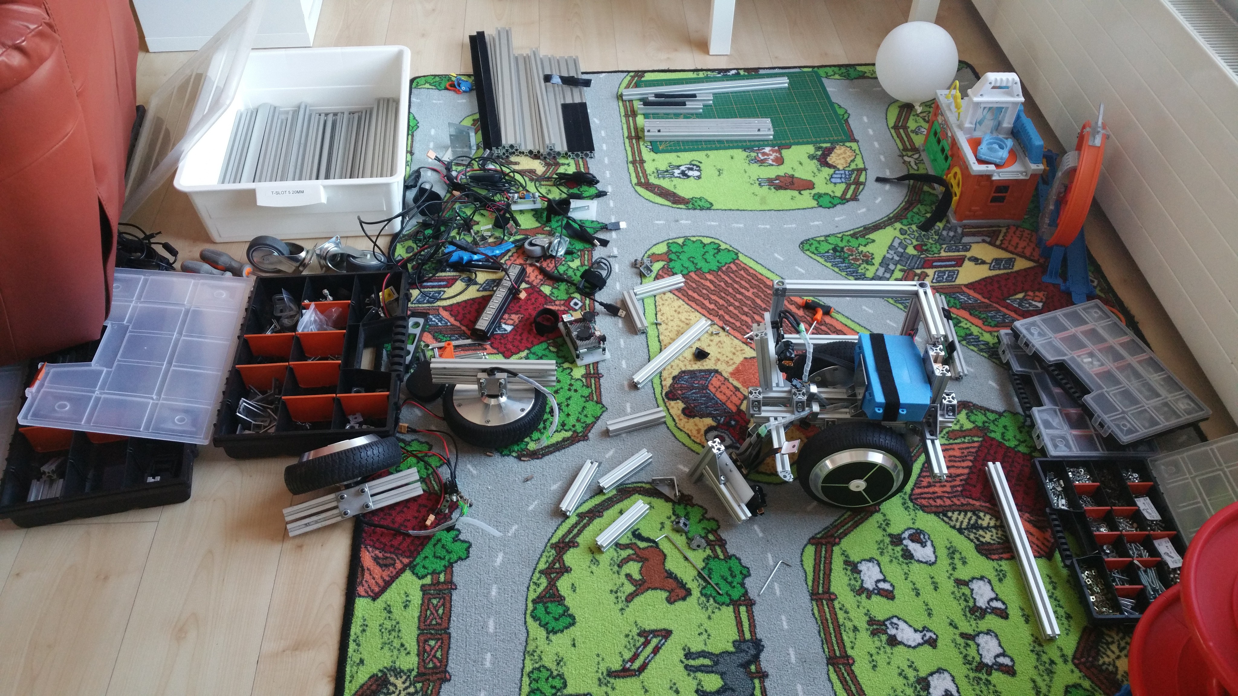
So I started another redesign. Which is actually a fancy word for saying I took it apart and started playing. Often I was assisted by my two fellow designers, my 8 year old daughter and 6 year old son, sharing a workspace together.
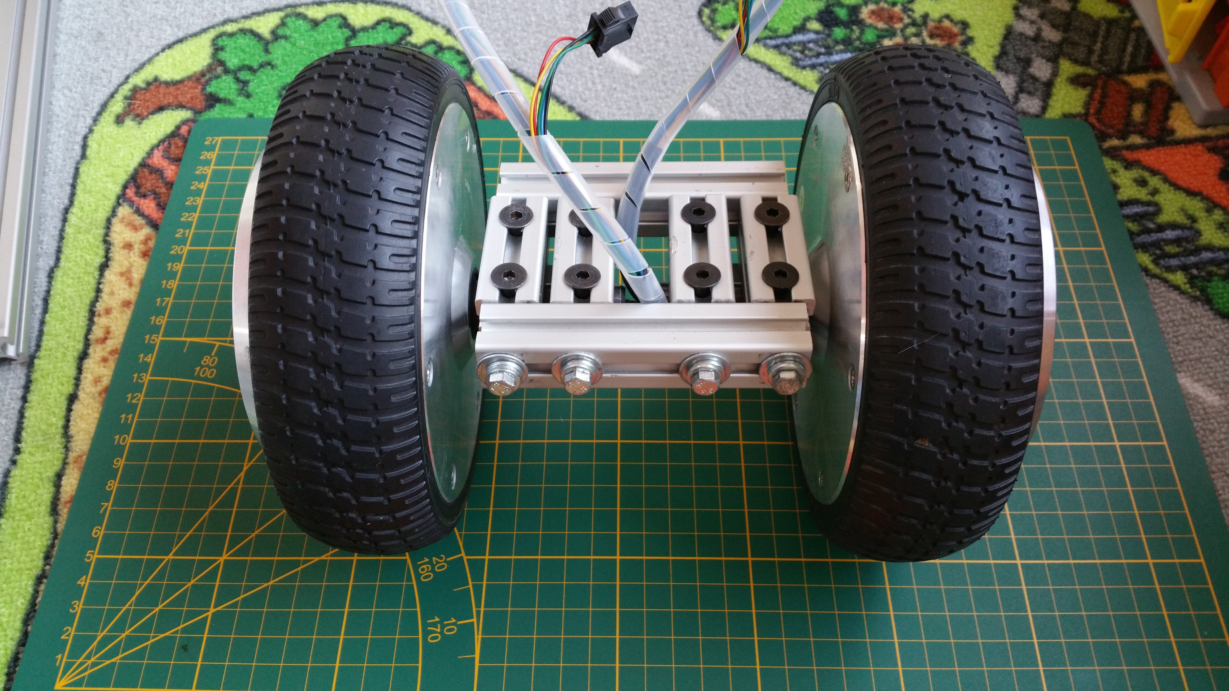
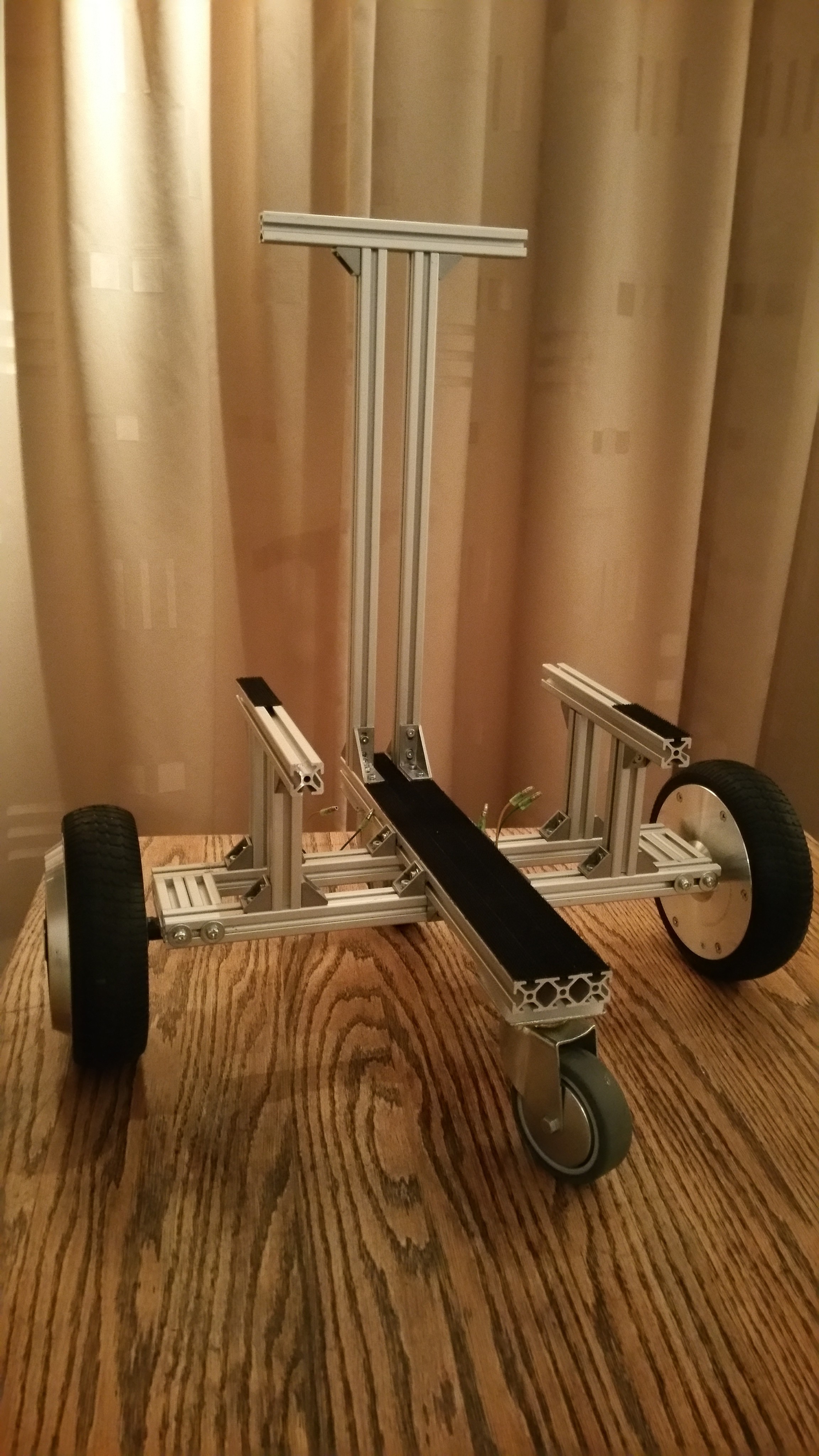
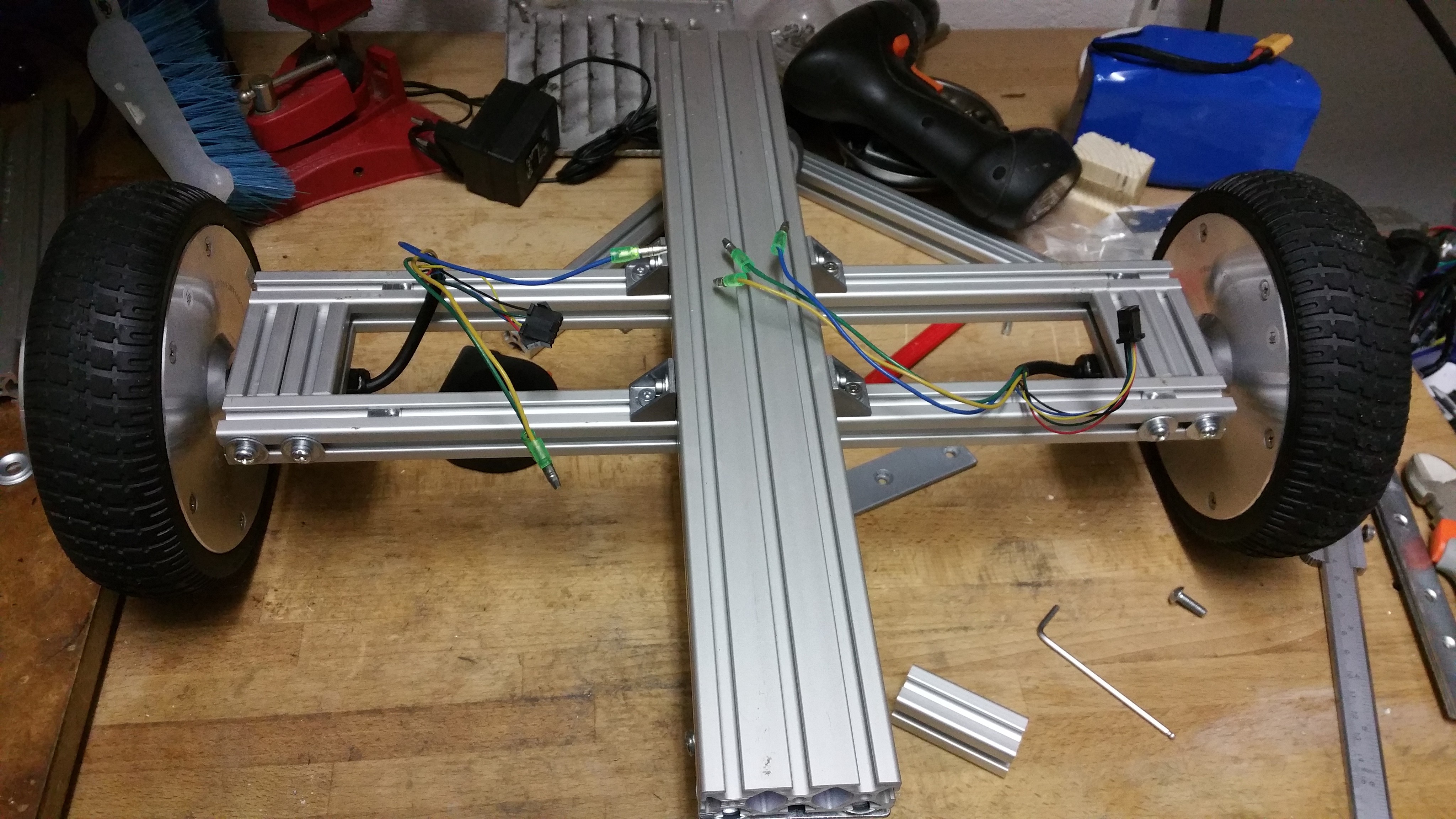
I started changing the way the wheels were mounted. Before I focused on modularity having two separate wheel assemblies connected to the frame. But now I focused on creating a small frame which would distribute the load better.
 ---------- more ----------
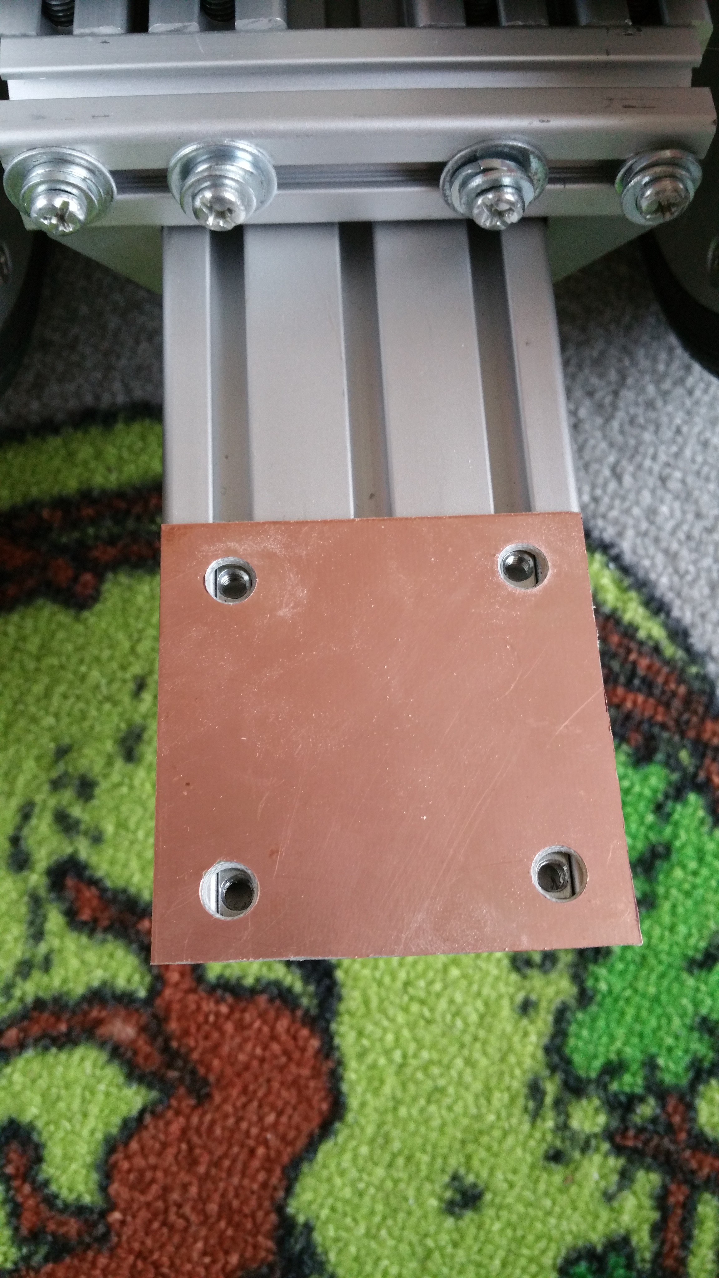
I wanted to be able to adjust the height of the caster wheel, to get the right amount of clearance to avoid slipping and limit the tilting of the robot when decelerating. A suspension system could also help, but I wanted to avoid that at this point to keep the design simple. As a first attempt I mounted the caster wheels on a piece of T-slot, allowing to change the height easily. But after some load testing (checking if the frame would support my weight) it became clear this design wasn't strong enough and wouldn't distribute the load properly.

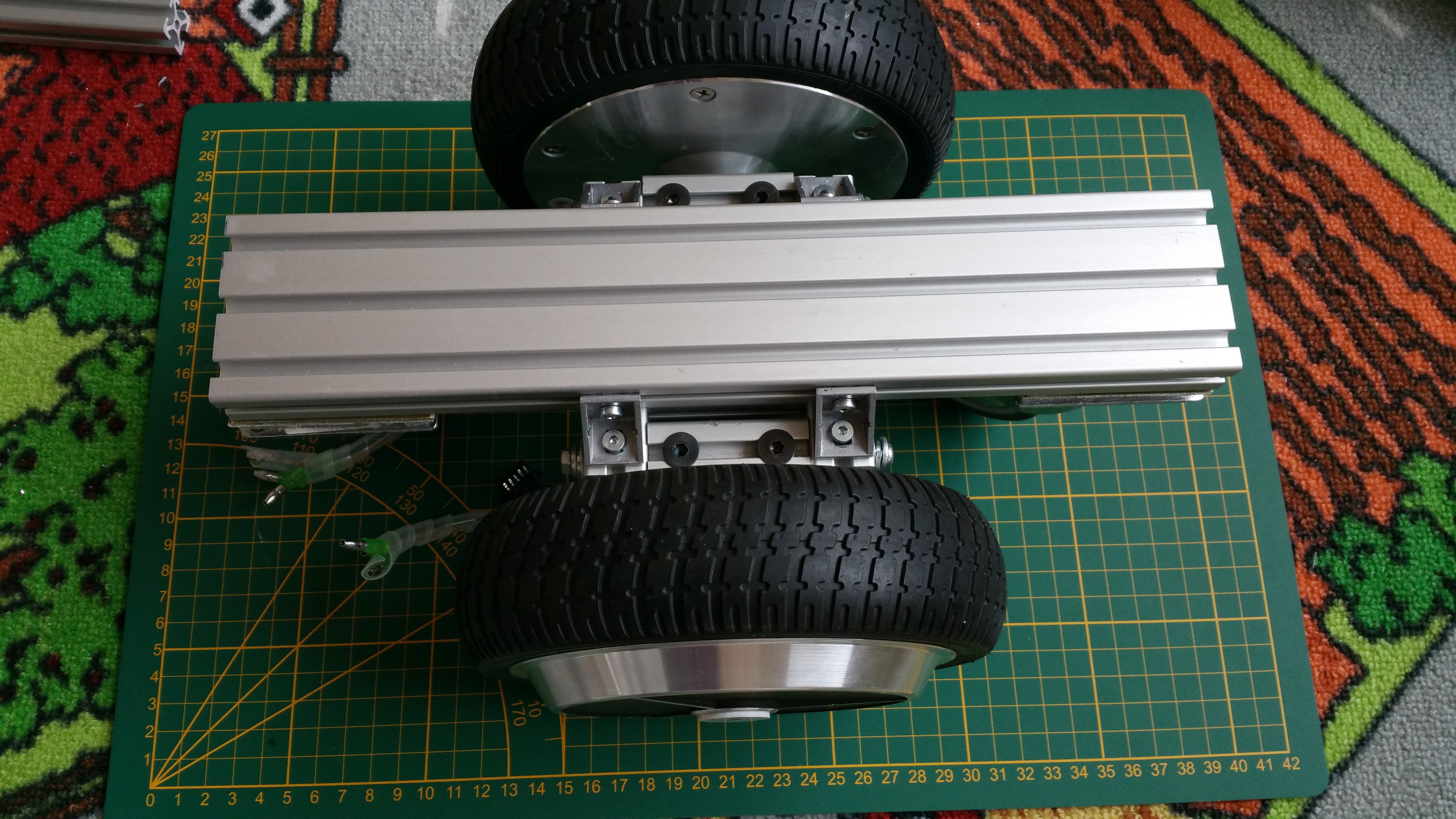
So I opted for a single piece T-slot to carry the load.
To get the right amount of ground clearance, I used some blank copper PCB boards as spacers.
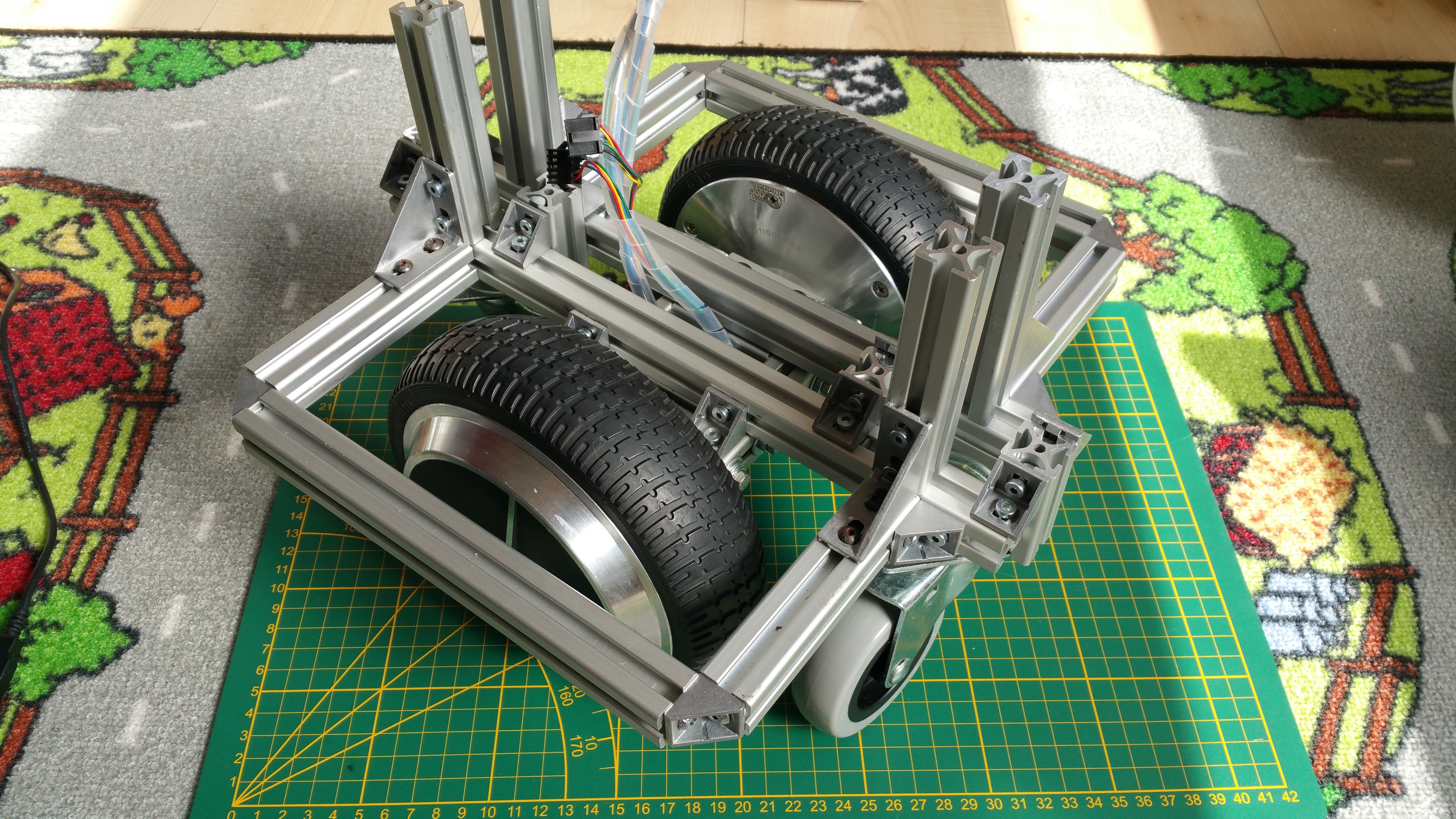
The idea is to have a strong base and attach side compartments for the electronics.

The base is assembled and is ready for the next step: wiring and adding the wheel sensor mounts.


-
Wheel encoder mount
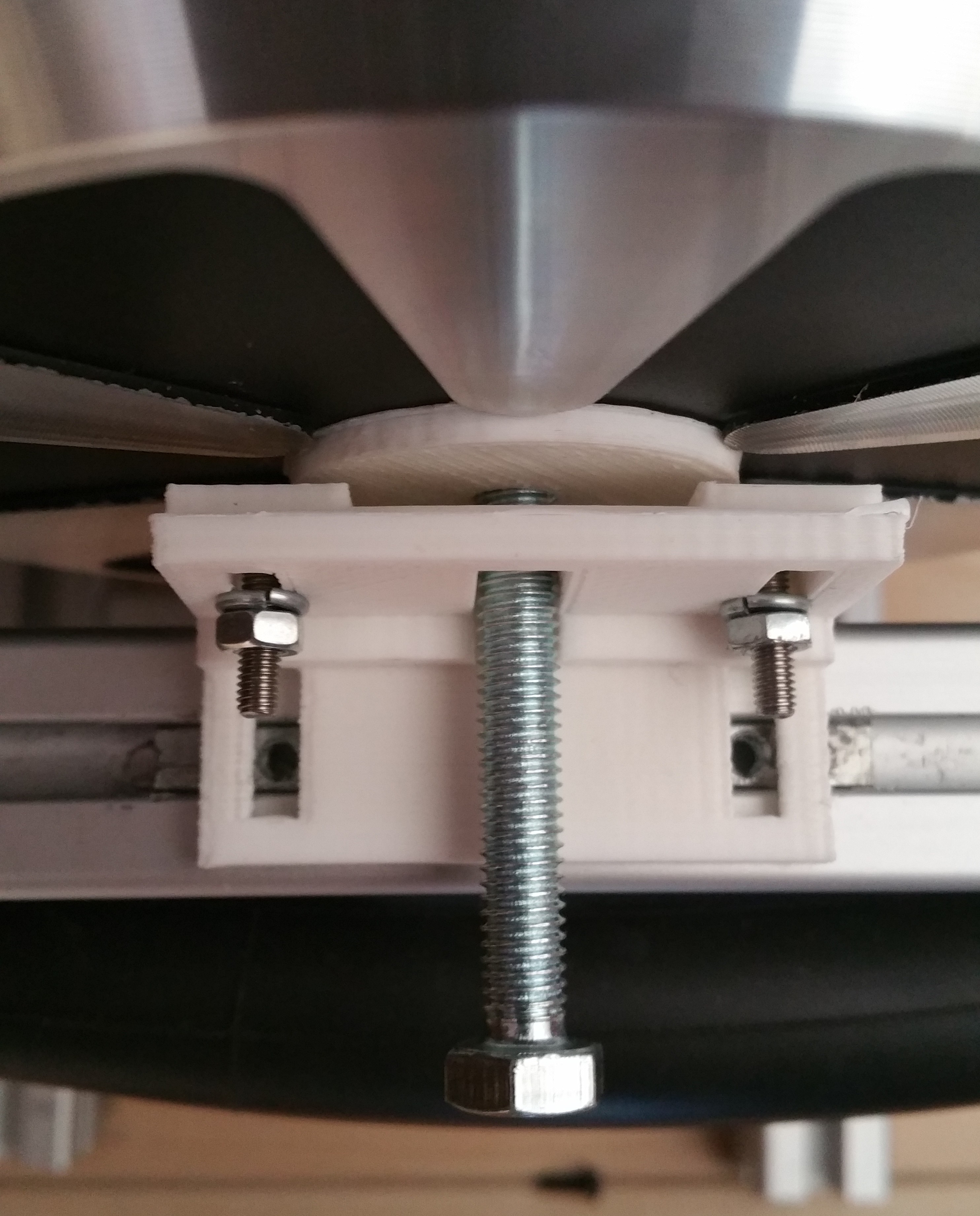
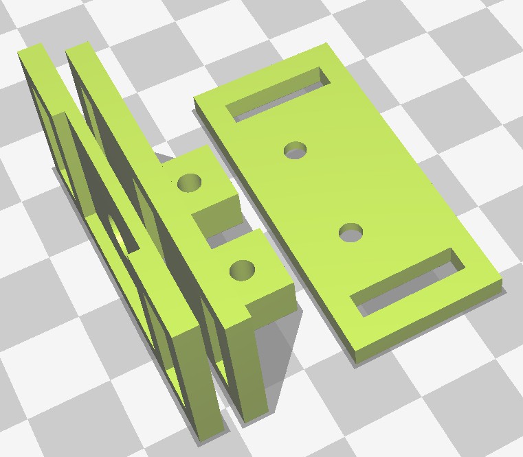
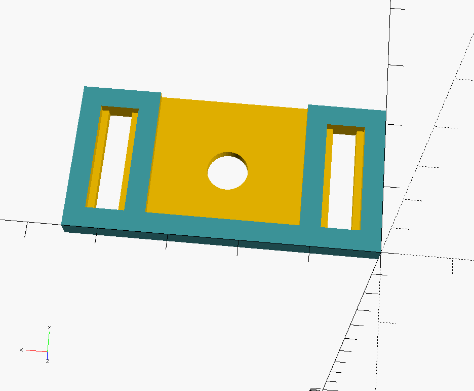
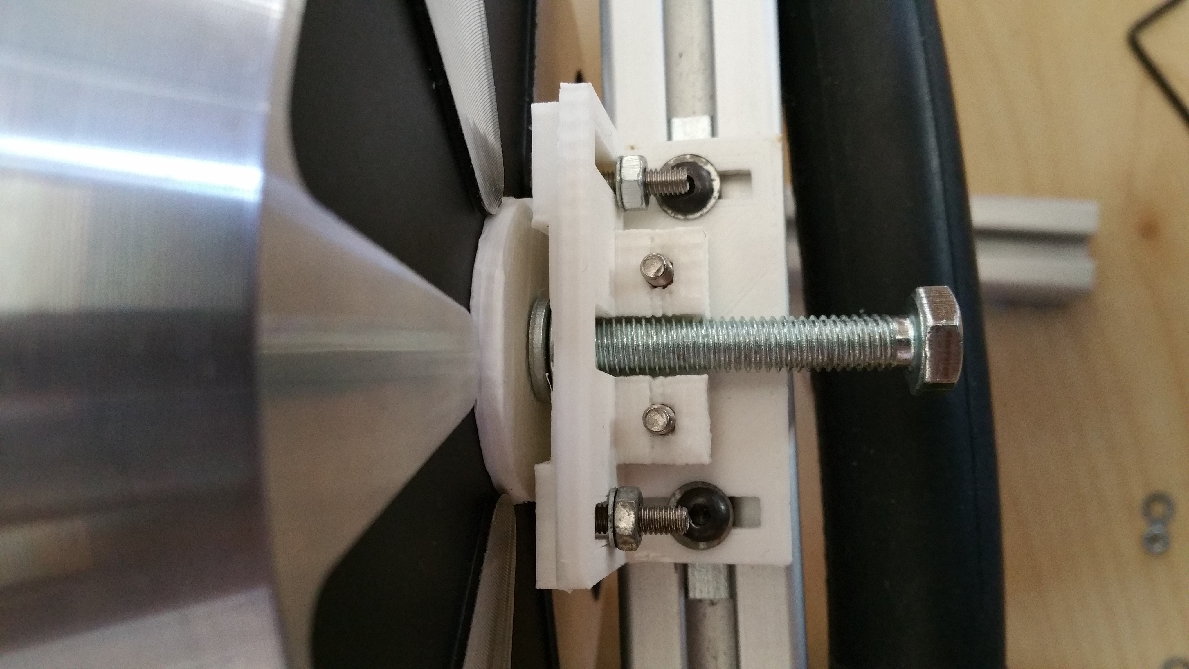
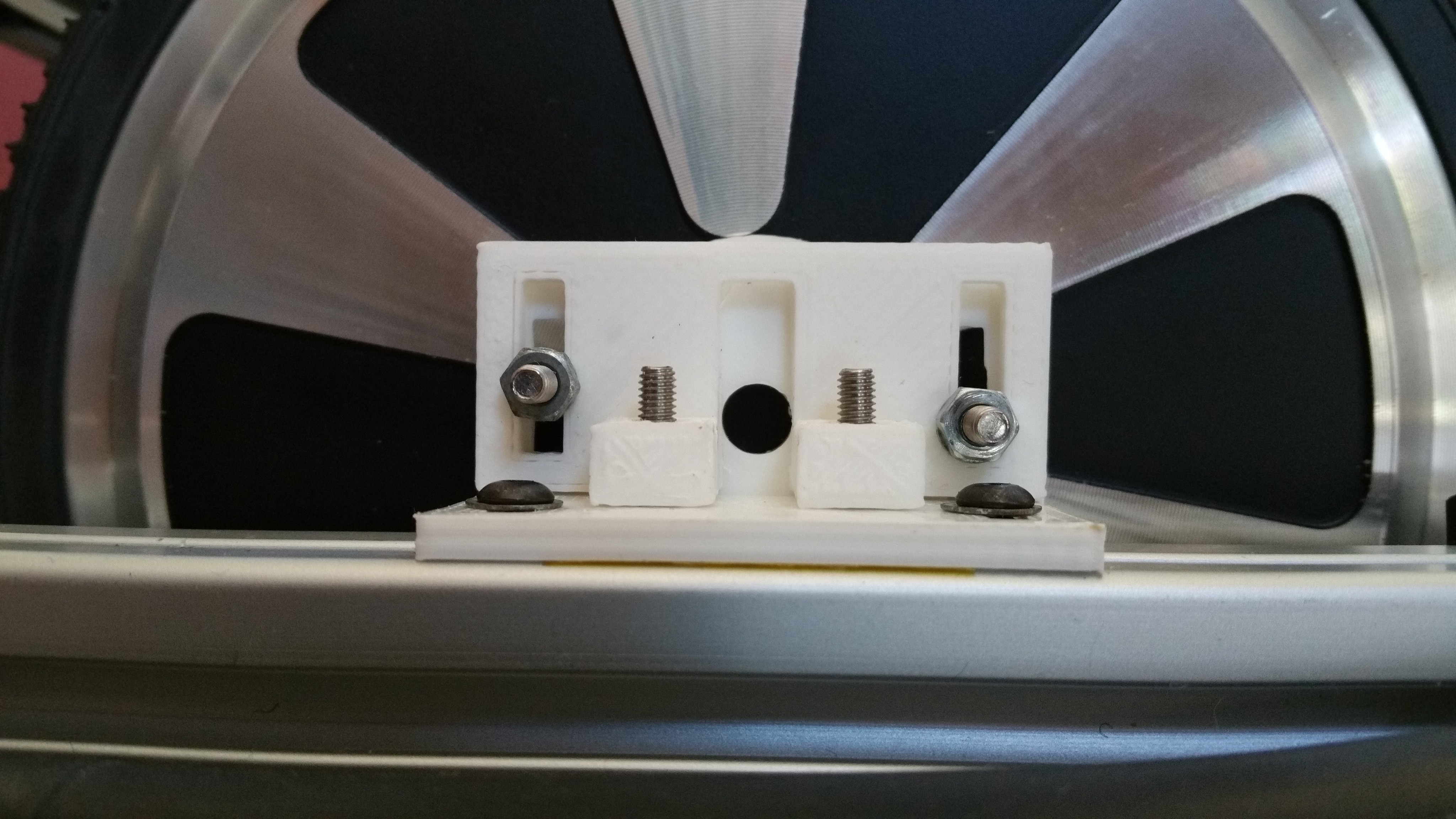
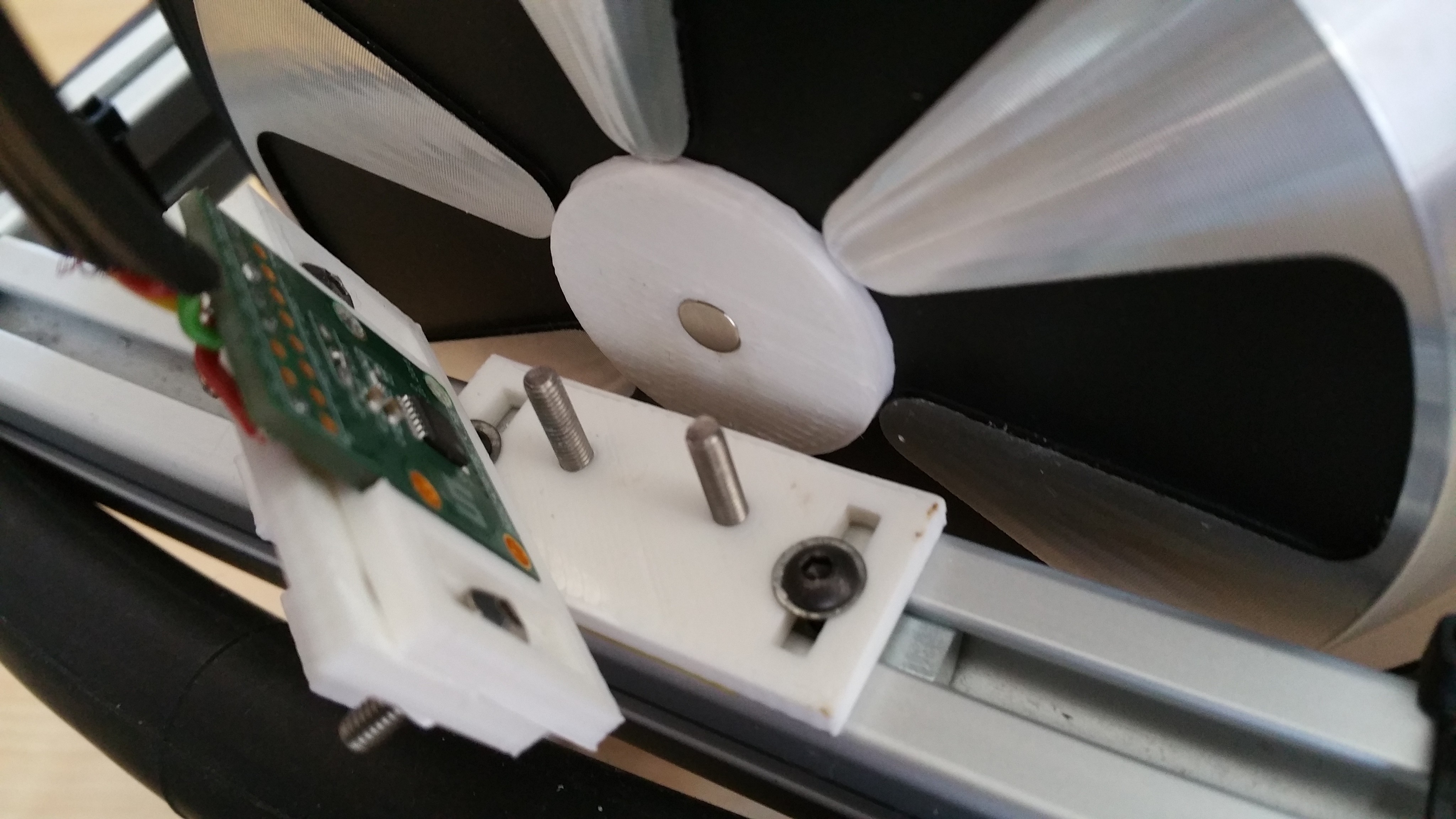
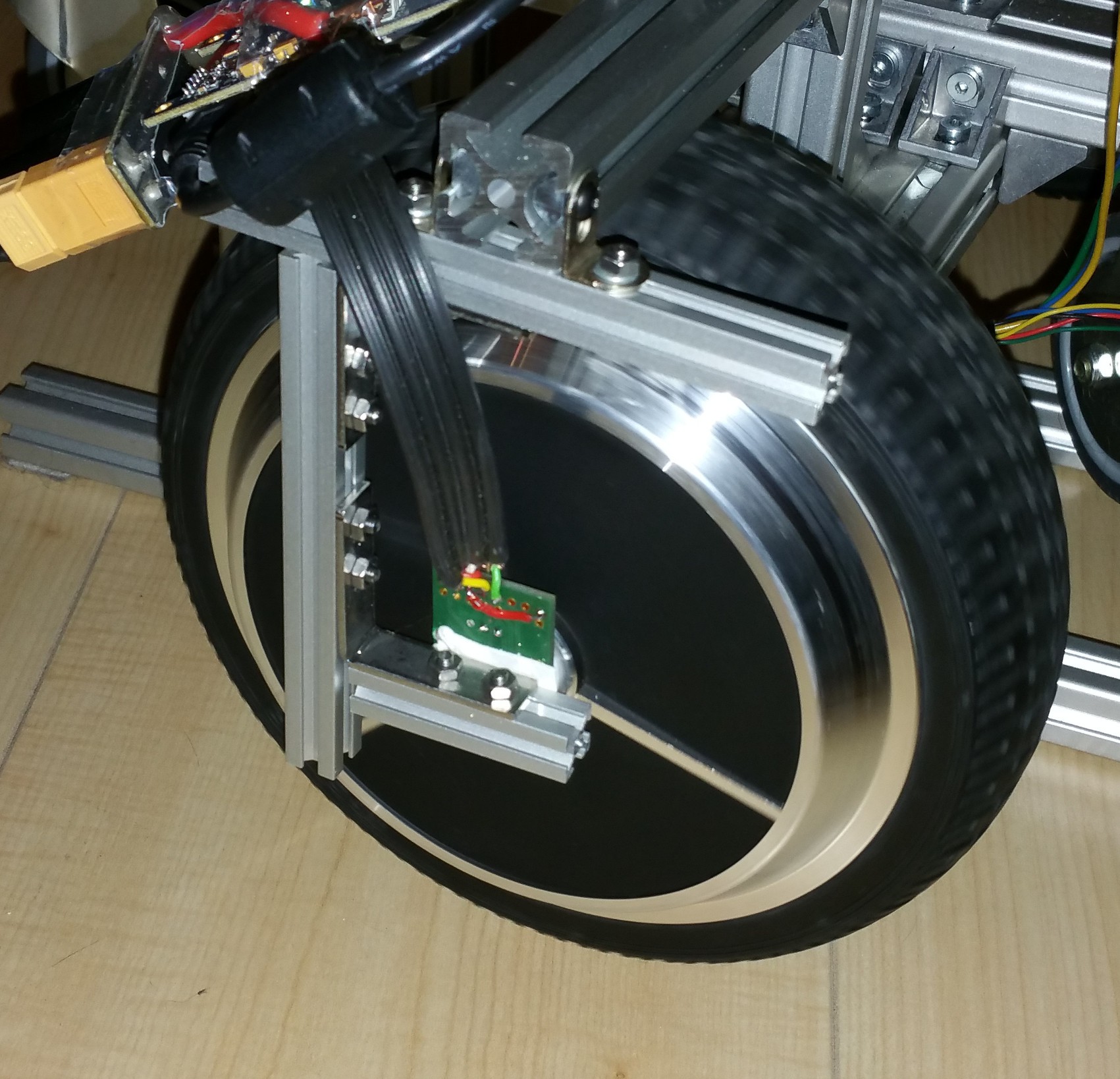
07/22/2017 at 08:26 • 0 commentsFor the wheel encoders I used the AS5047P development board. As a first attempt to mount the encoder on the new frame I used a piece of MakerBeam connected to two small angle brackets. While this somewhat worked, it relied on visual alignment. This was actually more guesswork since it's very hard to to see if the sensor was properly aligned. This needed some improvement, so I designed some brackets in OpenScad. Basic idea was to have an angle bracket with mounting slots to allow the positioning of the distance to the wheel and a sensorboard holder with mounting slots for further vertical alignment. At first I designed this as a 2 piece design, with the angle bracket as a single piece.
---------- more ----------For alignment the magnet is removed from the magnet holder and a M6 bolt is placed through the sensorboard holder and in the magnet holder. The sensorboard holder can then be mounted on the bracket, retaining it position after the bolt is removed. While this designed allowed the vertical alignment of the sensorboard holder relative to the mounting bracket, it would lose the horizontal alignment when the bracket was removed in order to be able to place the magnet and sensorboard. Also the vertical part was fragile and would easily break, caused by the limited strength in the z-axis for the part. So I split the design of the bracket in two parts.
Base bracket
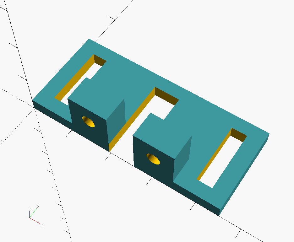
The base bracket is mounted on the T-slot profile. It has two slots to align the distance of the sensorboard to the wheel and the angle of the sensorboard to make sure it's parallel to the wheel. It uses two bolts for attaching the vertical bracket. I used two M3 bolts for MakerBeam because of their low profile and square head.
Vertical bracket
The vertical bracket is mounted on the base. Because it's now a separate part it can be printed in X/Y direction which results in a stronger part.
Sensorboard holder
The sensorboard is mounted to the vertical bracket with slots to allow adjusting the position for the alignment. It contains a cutout with the size of the sensorboard. A 6mm hole at the position the of sensor allows a M6 bolt to go through for alignment. Note: the part needs to be rotated before printing.
 In order to verify if the sensorboard is actually in the right position in the holder, I printed a sticker with the exact dimensions of the board and the position of the sensor. If the sensorboard is mounted properly, only the black area of the sensor should be visible and no purple should be visible.
Alignment process
Install the base bracket on the profile, but do not tighten the bolts yet. Mount the sensorboard holder and base vertical bracket using some m3 bolt and nuts. Tighten the nuts so that the sensorboard holder will retain its position, but still can be moved by hand.
Remove the magnet from the wheel magnet holder. Note: the design of the magnetholder could be improved with some cutouts around the magnet to make it easier to remove the magnet.
Insert a M6 bolt and some spacers to get a distance of somewhere between 0.5 to 3mm between the magnet and sensorboard. If all the parts are aligned correctly the screws for the base bracket and the bolts for the sensorboard holder can be tightened.
Removing the bolt and spacers will allow you to check the alignment.
The vertical bracket with sensorboard holder can now be removed to allow installing the sensorboard and magnet. With the sensorboard alignment sticker you can verify if the sensorboard fits properly and the sensor is at the right position.
Note: Do not forget to put back the magnet! One time I got distracted while I was working on this. When testing the motor it made a loud rattling noise and caused a partial short in the motor. End result being one motor that doesn't run smoothly any more. I may have had the current limits setup to high, but still a simple double check avoids such trouble. I ordered a second hoverboard to continue the project. I also ordered a second hand motor and hopefully I can make a working pair out of these parts. Since the outside pattern of the hub motor differ in design I had to increase the size of the magnetholder.
Design files
The design files are available in source code (for OpenScad) and STL format in the morph_design repository.
-
Source code morph stack
07/21/2017 at 08:00 • 0 commentsI've linked the main repository containing the source code for the morph stack for use in ROS. The stack consists of separate packages, each have their own repository but are linked as submodules from the main repository which is linked.
- morph_bringup : contains launch files and parameters for bringing up the robot
- morph_description : provides the robot model
- morph_hw : provides the robot driver for creating a differential drive mobile base
- morph_navigation : contains launch files and configuration parameters for using the navigation stack
- morph_teleop : provides launch files for teleoperation of the robot using keyboard or X-box controller
I've forked the VESC repository from the MIT-Racecar project in order to merge the commits of pull request 7 which contains changes to publish the rotor position. I've been testing this to get more detailed odometry.
See the readme of the morph repository for installation instructions. This is very much a work-in-progress but at least it will show the current state of development.
-
Design #4: Improved concept
07/18/2017 at 18:29 • 0 commentsWith good results from the encoder it was time to address some of the issues and do another (you guessed it) redesign. Let me start by showing the result first, for a change. I will go into the details after the break.
Frame design
While the initial results of the encoder were very promising, the mounting of the sensor was a bit fragile. A small bump would move the sensor out-of-range resulting in the wheel no longer being controllable. Since I also wanted the frame to be even more smaller I redesigned the frame to have the wheels as close to each other as possible and have a beam enclose each wheel to allow the mounting of the encoder board with protection.
Before I mounted the (heat shrinked) VESC's using some Velcro straps, but now they needed to be mounted more securely, because of the added cable for the encoder. So I mounted them on a piece of 8mm polyethylene. Because the mounting holes are somewhat dangerously close to the power connections, I used plastic standoffs and bolts to mount them. Since I didn't have the right connector at the time, the sensor cable is soldered directly on the connector.
Computer
I had ordered a Intel Robotics Developer kit with a RealSense R200 earlier with the idea to have it run the basic navigation and driving of the mobile base. It could be complemented by a faster computer (on- or off-robot) for additional processing later. The robotics developer kit comes with an UP (first generation) board, a Raspberry PI sized computer with an Intel x5-Z8350 Atom quad core processor with USB3 (for the RealSense camera). Main benefit being the smaller size and weight, while still have enough performance to run the navigation stack and even visual odometry. I like the small size of the RealSense camera, which allows it to be mounted lower and keep the base compact. For now I ditched the idea of having a screen thinking this could be added later if needed. But the introduction of the UP board required me to change the power supply. The UP board is powered by an XL4015 DC-DC converter and required another power connection.
Power supply and soft start
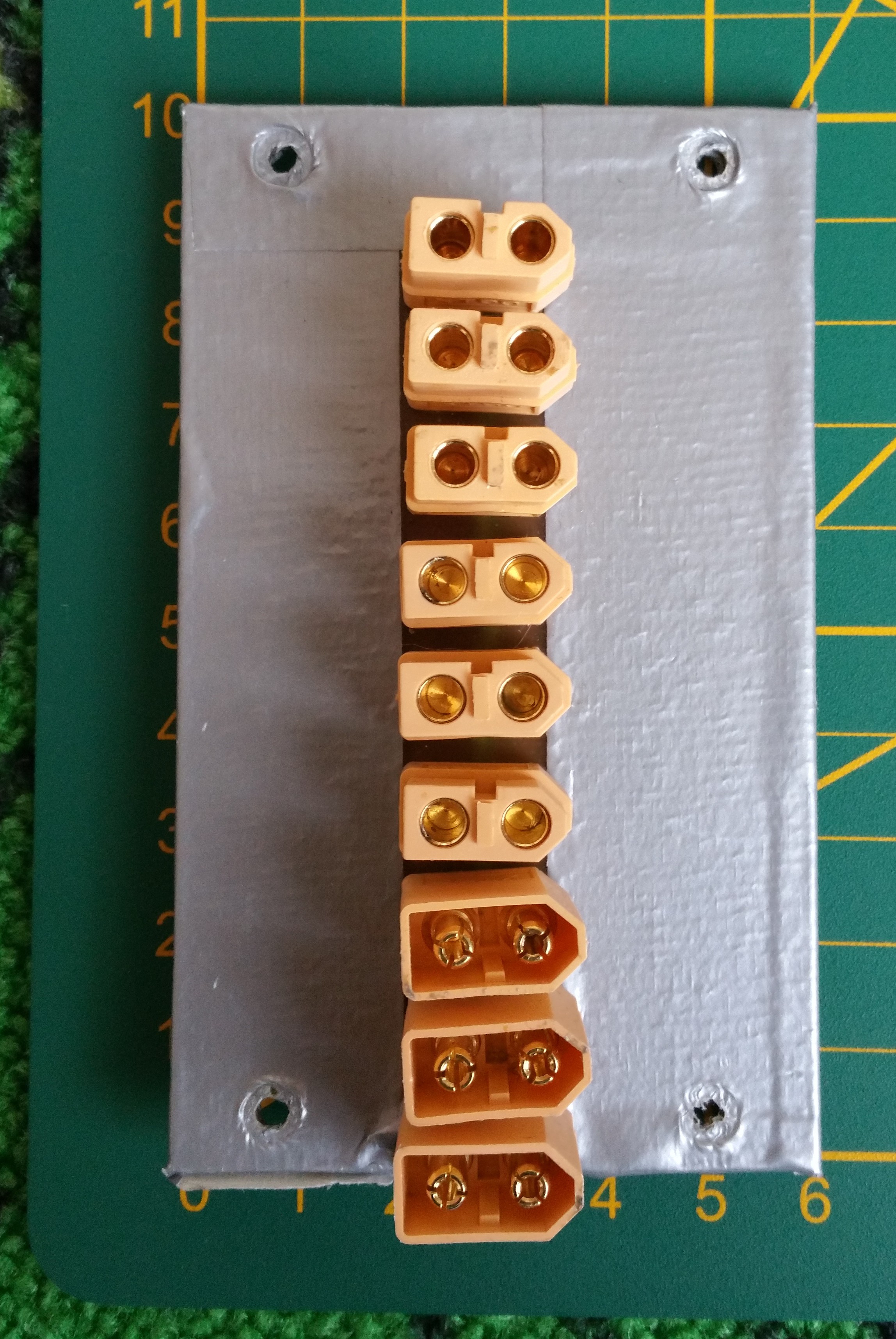
Before I created a power supply splitter cable with 1 in 3 out XT-60 connectors to power both VESC's and one additional DC-DC converter for the Kinect sensor. This had already shown its limitations as I now needed an additional DC-DC converter for the UP board. So I prototyped a powerstrip board with 3 in and 6 out XT-60 connectors. The idea being to connect up to two batteries and the charger connector as input and up to 6 devices as output. The board was created manually from blank copper FR4 with a knife to create the isolations and manually drilled the holes for the connectors. The result is a bit ugly, but it works. For now it's used as a powerstrip, but I'm also considering the idea of creating a backplane board holding DC-DC converter daughterboards to create a modular power supply. This would have the benefit of providing the electrical and mechanical connection and the ability to share a cooling fan. Either way it's on my todo list to design a PCB for this and add a car mini-fuse holder for each connector for added protection. In the current situation I only have one 10A fuse wired at the switch and rely on the BMS for further protection.
For the inrush current, soft start solution, the car relay system worked, but I wasn't satisfied with it. For one, I didn't like the power consumption of each relay (~200mA at 12V). Also it created a wiring mess and was a bit too bulky to my taste. So after investigating some more, it made sense to limit the inrush current with a pair of NTC thermistors. After some calculation I ended up ordering some NTC 5D15 thermistors, which have a 5 ohm (@25 degree celsius) resistance and diameter of 15mm, which would allow a continuous current of 6A. By using two in parallel for each VESC the current would be limited to 4.2A while charging the capacitors. I added the NTC's in the power cable for the VESC's and heat shrinked them for protection.
Bumper
I wanted the robot to be safe to run into and wouldn't cause pain or damage. So the idea of adding a bumper was in my mind for a while. I liked the idea of having a soft bumper and perhaps also being able to sense if something was touched. So I started experimenting combining the inner tube of a bicycle tire with an inexpensive digital pressure sensor BMP280. In order to get the sensor inside, the tire had to be cut and resealed. I tried the thinnest wires I had, but still wasn't able to get a good seal. I ended up using a flat flex cable (FFC), originally used for connecting a Raspberry Pi camera. This, combined with a foldback clip ended up working pretty well. I used a Wemos D1 with a simple ros_serial sketch to publish the float value of the pressure and did some testing. So far the bumper proves to be effective both mechanical in preventing pain or damage when running into the robot and in a way to provide a all-round bumper sensor. Further work is needed to integrate this in ROS. I also would like to do some more experimenting to see if I could pin-point the location of a hit with the use of two sensors combined with time-analysis. Another alternative would be to divide the bumper into segments and have a separate sensor for each segment.
Encoder mountIn order to get better alignment of the encoder with the magnet I designed some brackets in OpenScad to hold and adjust the board. More details to follow...
-
Encoder
07/18/2017 at 07:57 • 0 commentsIn order to improve the odometry data I wanted to add an encoder. The downside of using a brushless DC outrunner hub motor is there is no shaft to mount an encoder to. The shaft fixed to the robot remains stationary and only the wheel turns. The VESC already had support for the AS5047 magnetic rotary sensor and I read a positive experience about that sensor. It seemed doable to mount a magnet to the side of the wheel, so I ordered some development boards. The development board contains the sensor mounted to a small PCB and a diametric magnet of 6mm diameter and 2.5mm depth.
First step of testing the encoders was removing the RC filters on the hall sensor port as Benjamin describes very clearly in his video.
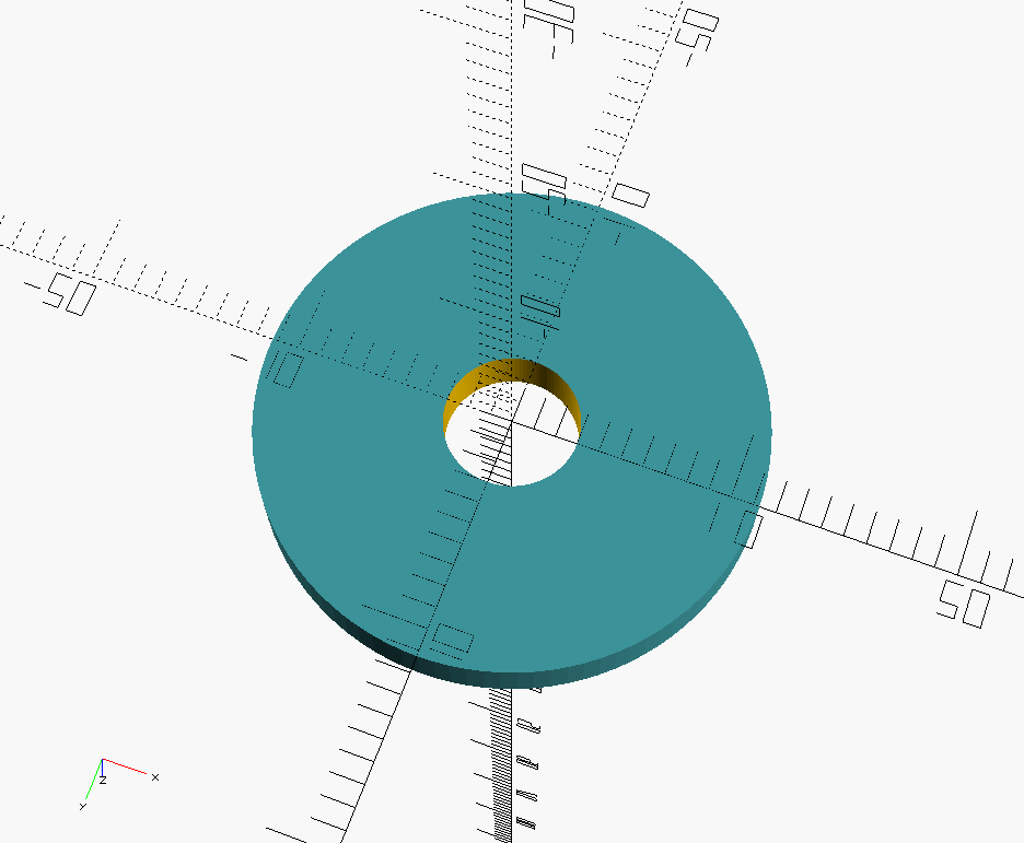
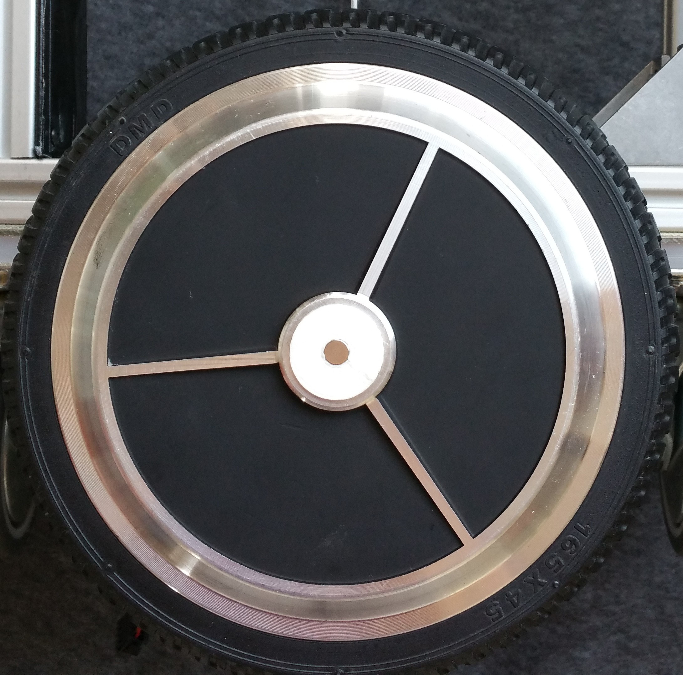
Next step was mounting the magnet exactly centered at the outside of the wheel. The wheel already has a circle with an elevated edge, so I just needed to create an holder which would fit within. Literally 3 commands in OpenScad:
difference() {
    cylinder(2.5,11.25,11.25);
    cylinder(2.5,3,3);
}
And after a short print the magnet would fit snugly on the wheel within the holder:
Now the only step remaining was mounting the sensor board. I created a frame out of some MakerBeam and brackets and attached the sensor board with some removable double adhesive tape. The slots in the MakerBeam would allow me to adjust the position of the board to align with the magnet. When I first tested the board with regular header wires it didn't work: the readings went back and forth all over the place. It seems the high speed SPI over the distance of ~20cm combined with the electrical noise of the hub motor required some shielded wires.
-
Design #3: Initial concept
07/17/2017 at 08:30 • 0 commentsAt this stage I had a simple proof-of-concept, but with some flaws I wanted to address:
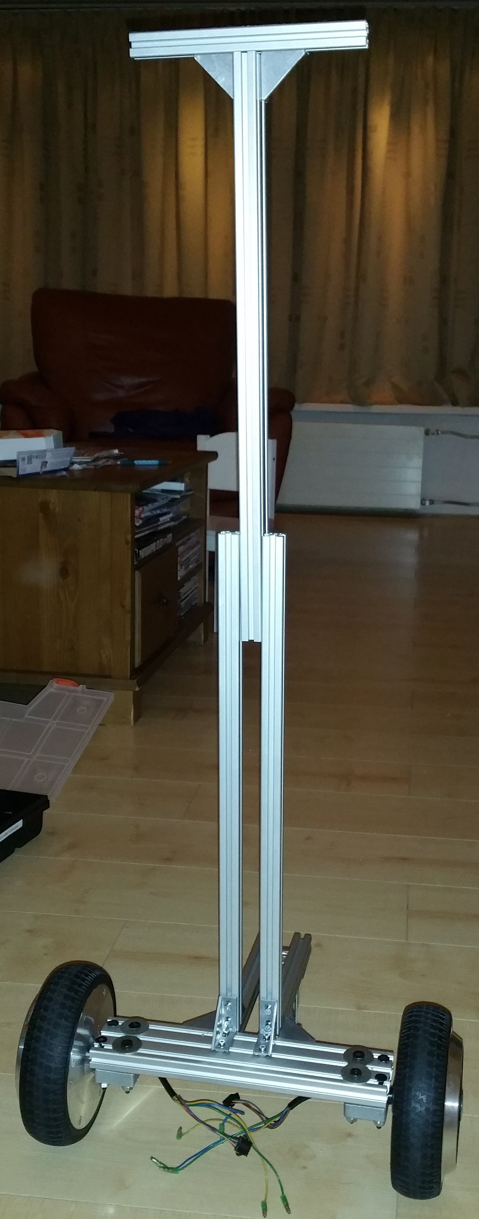
- I didn't like the Turtlebot-shape of the robot, I wanted a more close to human size robot (around 1m50 / 1m60) which could carry a load.
- The wheels mounting brackets were failing. The added weight of the old laptop caused the brackets to misform.
- The old laptop I used was too slow to run gmapping in order to try to create a map and also had some Wifi reliability issues.
- The VESC's were driving the motors in BLDC mode, causing a high-pitched noise while driving. I wanted to drive the motors in FOC (Field Oriented Control) mode, which should make them more quiet.
- The large inrush current caused by the VESC's capacitor banks would trip the safety of the BMS integrated in the battery pack, which meant I couldn't use the switch to turn on the robot, but had to connect each VESC's power one by one.
So it was time to start over and try a new design. Instead of just a test frame, I started building a first version of the concept I had in mind. Things were changing at a rapid pace and I should have documented better to have something more to show for it.
Frame design
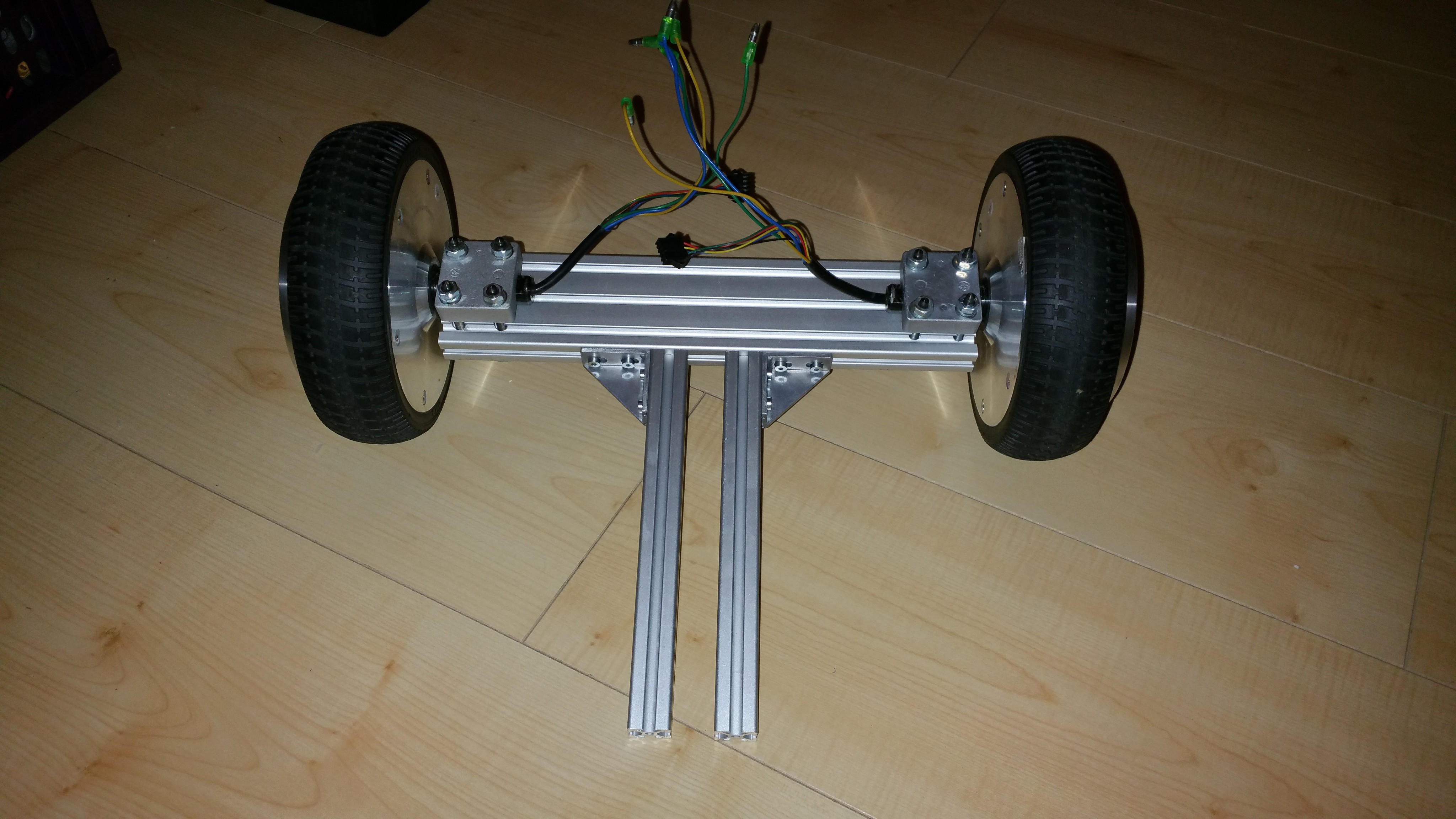
I drilled 6mm holes in an 6x2cm T-slot profile beam and mounted the wheels with M6 bolts with the mounting blocks which were harvested from the hoverboard. The frame was made smaller and taller.Laptop replacement
I replaced the old HP laptop with a Yoga 510-14ISK laptop. This has an I5 processor, 4GB memory, SSD and a full HD touch screen with the option to flip the keyboard behind the screen (360 degree hinge). This makes it possible to have a screen in the robot and save the cost of a separate tablet.
Soft start
The large inrush current not only tripped the safety of the BMS, but also created sparks at the XT-60 connector eroding the contacts of the connector. To remedy this, I used some car relays to power on the VESC's one at the time triggered by an Arduino Nano.
FOC modeIn BLDC mode the phases are switched on and off at a high frequency, causing a high pitched noise. With Field Oriented Control the phases are driven in a sinusoidal pattern, reducing almost all switching noise. Low noise was one of my primary design goals. I didn't want any gear noise, which was why I opted for brushless hub motor. So the switching noise was also annoying and should be avoided. Hence I had to switch to FOC mode. Unfortunately switching to FOC mode caused some more issues than I anticipated. Apparently in FOC mode the PID control loop for speed control in the VESC firmware is much slower then it is for BLDC mode. This caused the motor to oscillate back and forth. With some PID tuning I was able to get the control stable for a certain ERPM (for instance 500), but it would still oscillate at lower ERPM and I couldn't get it stable within the range I needed. So after reading through the forums and suggestions I switched to duty cycle control instead of speed control. This solved the control issue for the VESC, but required the robot driver to be rewritten in order to convert the required speed command to a duty cycle parameter.
End result
The end result was a huge improvement from before. I really like the absence of noise in FOC mode. Also the height of the robot is much better. But there were still some issues remaining:
- Odometry data was not good enough to build a map
- The base is still to wide to drive in some of the smaller areas in my living room
- The laptop is too heavy at the top, causing the robot to tilt when breaking
- There was some slippage when the ground is somewhat uneven caused by the caster wheels lifting one of the drive wheels. Adjusting the ground clearance of the caster wheels is crucial to prevent this.
-
Design #2: Turtlebot-like test frame
07/16/2017 at 17:48 • 0 commentsFor the next step, I wanted the robot to be controllable from ROS. I changed the initial design to be more Turtlebot-like to be able to hold a laptop running ROS.
Changing the frame was the easy part, most of the work has gone into creating the ROS integration. Thanks to the MIT-Racecar project, there already was an open source VESC driver which I could use. This meant I didn't have to implement the serial communication which saved a lot of time. Because I wanted a modular solution I wanted to implement the driver using ros_control. In ros_control a robot driver exposes joints which can be controlled using a velocity, effort or position interface. For wheels this means we need to implement the velocity interface. The velocity interface accepts the desired target speed as a command (in rad/s) and reports the actual speed as feedback of the current state (also in rad/s off course). The joints are controlled using a controller implementation, for which ros_control already provides some, including a differential drive controller.I will go over the software in more detail at a later stage and off course provide all the source code. There's still some renaming, cleaning up and license stuff to do. But for now I will just describe the steps I did in order to create the bare minimum ROS integration. At the time I did not have a name for the project and used 'r16' as a project work title and as a prefix for the ros packages. I followed the convention used by the turtlebot and other projects to create separate packages for the robot driver, description and bringup launch files.
1. Created hardware interface package ' r16_hw'
Following the documentation I created a new package to contain the robot driver. The class 'wheel_driver' uses the vesc_interface class from the MIT-Racecar project to do the actual communication with the VESC. The wheel_driver is used in the class to drive the robot and registers two velocity joint interfaces named 'left_wheel_joint' and 'right_wheel_joint'.
2. Created a simple robot description package 'r16_description'
In ROS the way to describe your robot is with an robot model described in a XML file in Unified Robot Description Format (URDF). There's plenty of documentation and tutorials for this on the ros wiki. In order to be able to use variables, reusable blocks and expressions the URDF is often created in the Xacro template language. I created a very simple representation of the robot containing of the two wheels attached to a fixed beam and two spheres representing the caster wheels attached to their own beam. For the differential drive to work properly the joints must be declared in the URDF file using the same names ('left_wheel_joint' and 'right_wheel_joint'). Also the parent link and child link must be set accordingly. It's the information in the parsed robot model that the differential drive controller uses to get the wheels circumference and distance between both wheels and calculate the odometry accordingly.
  ...
  <joint name="left_wheel_joint" type="continuous">
    <parent link="base_link"/>
    <child link="left_wheel"/>
    <origin rpy="0 0 0" xyz="0.0 0.2225 0.0825"/>
    <axis rpy="0 0 0" xyz="0 1 0"/>
  </joint>
  <joint name="right_wheel_joint" type="continuous">
    <parent link="base_link"/>
    <child link="right_wheel"/>
    <origin rpy="0 0 0" xyz="0.0 -0.2225 0.0825"/>
    <axis rpy="0 0 0" xyz="0 1 0"/>
  </joint>
  ...
3. Created 'r16_bringup' packageThe bringup package contains the launch file to bringup the robot. This loads the description of the robot, parameters used by the mobile_base_controller, the robot driver and the mobile_base_controller which will load the differential drive controller.
<?xml version="1.0"?>
<launch>
    <!-- Convert an xacro and put on parameter server -->
    <param name="robot_description" command="$(find xacro)/xacro.py $(find r16_description)/urdf/r16.xacro" />
    <!-- Load joint controller configurations from YAML file to parameter server -->
    <rosparam file="$(find r16_bringup)/config/r16.yaml" command="load"/>

    <!-- Launch robot hardware driver -->
    <include file="$(find r16_hw)/launch/r16.launch"/>

    <!-- Load the differential drive controller -->
    <node name="controller_spawner" pkg="controller_manager" type="spawner" respawn="false"
        output="screen" args="mobile_base_controller">
    </node>
</launch>
The parameters are described in a yaml file and tells the mobile_base_controller to load the differential drive controller. It also provides the parameters for the differential drive controller so it knows which joint names to use and get the details from the robot description.
mobile_base_controller:
  type: "diff_drive_controller/DiffDriveController"
  left_wheel: 'left_wheel_joint'
  right_wheel: 'right_wheel_joint'
  pose_covariance_diagonal: [0.001, 0.001, 1000000.0, 1000000.0, 1000000.0, 1000.0]
  twist_covariance_diagonal: [0.001, 0.001, 1000000.0, 1000000.0, 1000000.0, 1000.0]
In the end by running the bringup launch file it is possible to control the robot using an X-box controller using the turtlebot_teleop package as shown in the video below. There were still some issues in code, mainly conversion between rad/s and ERPM required for the VESC, resulting in a too high value and somewhat sensitive to control, but as a concept it worked.
-
Design #1: Test setup
07/15/2017 at 20:44 • 0 commentsThis has been a pet project for about a year now, and I would like to start by giving a short summary of the past design iterations. While having a general idea in my head, I didn't start with a clear end-design. Instead I focused on rapid prototyping each step to test each assumption along the way and iterate the design.
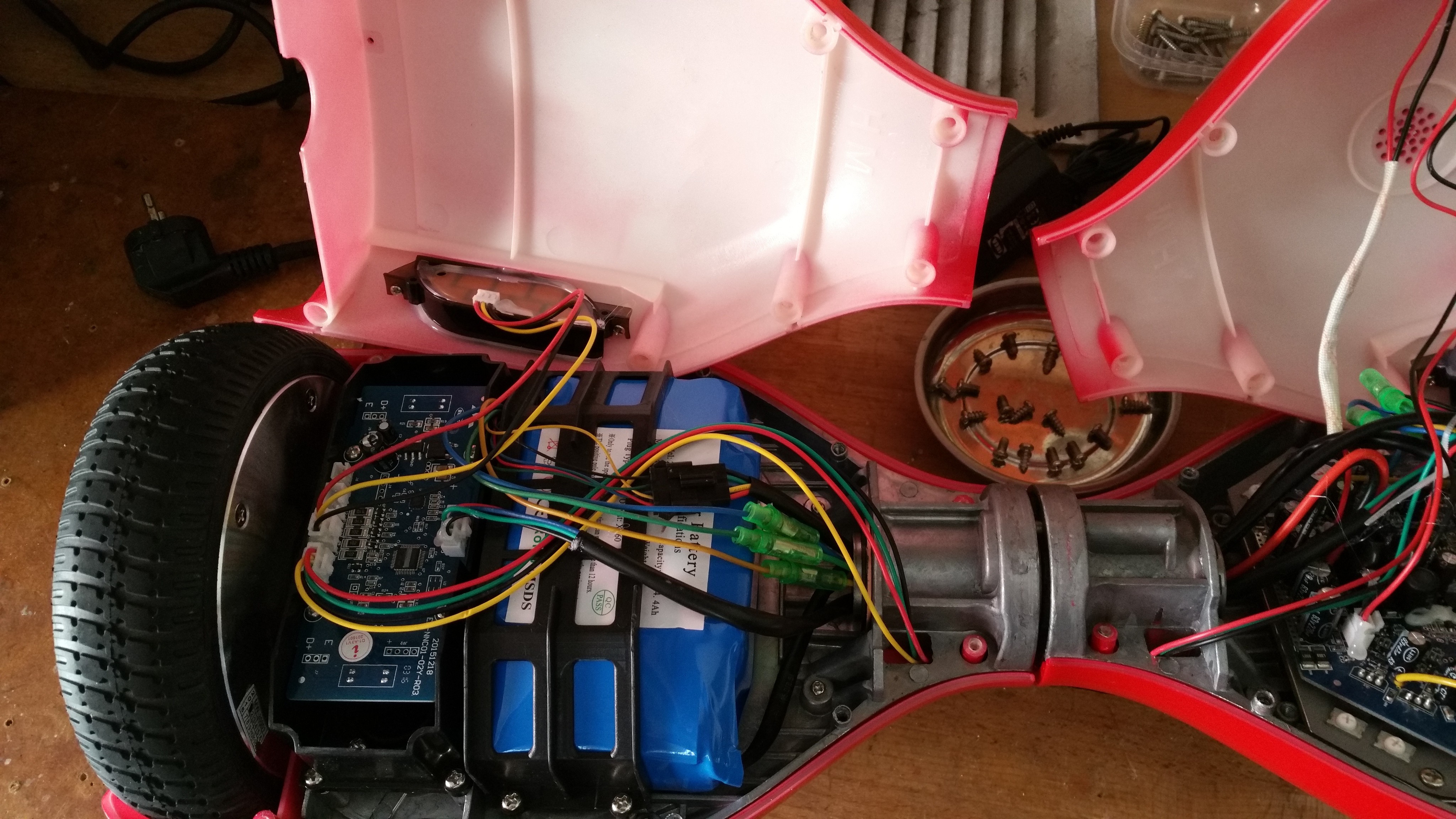
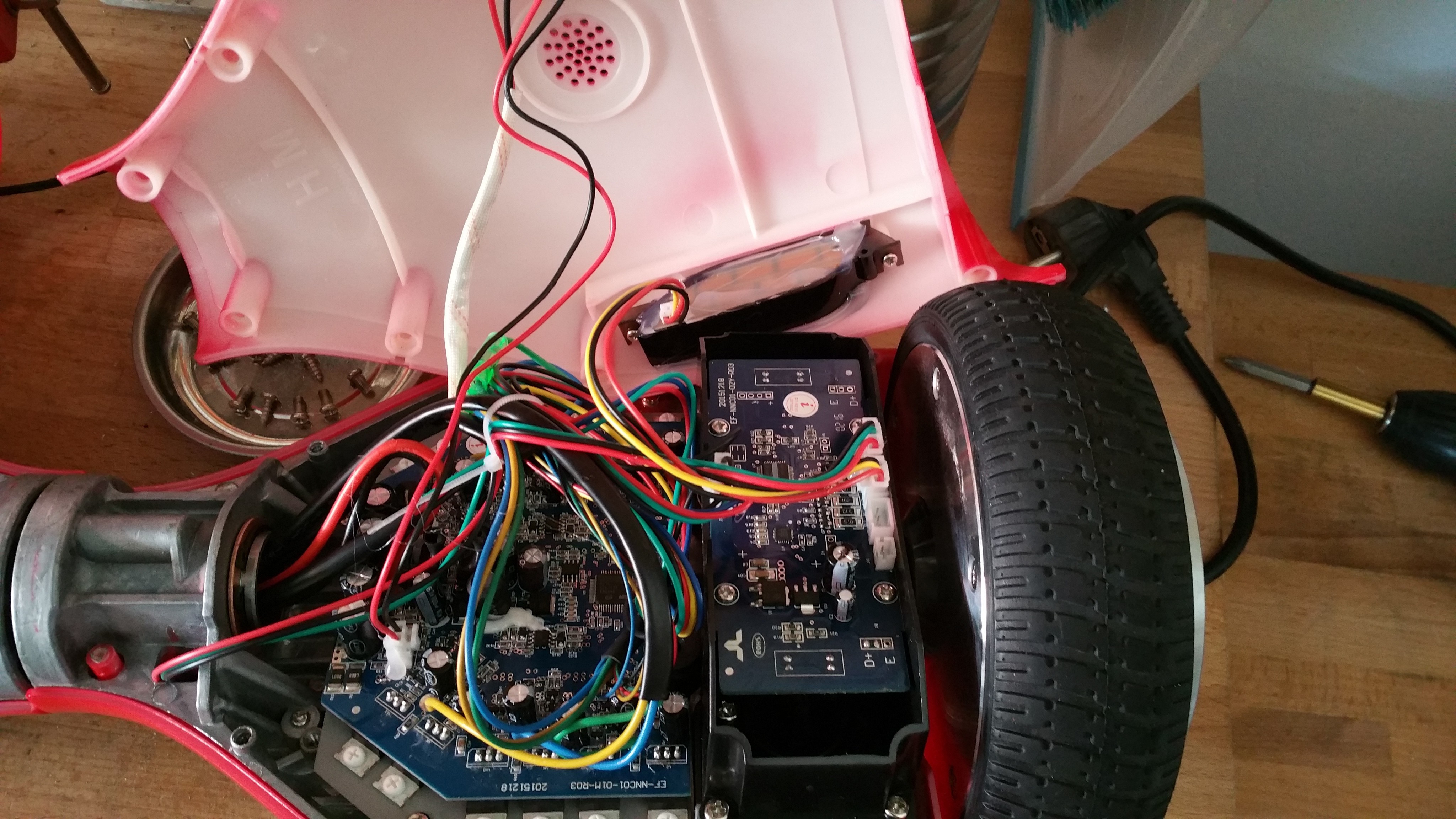
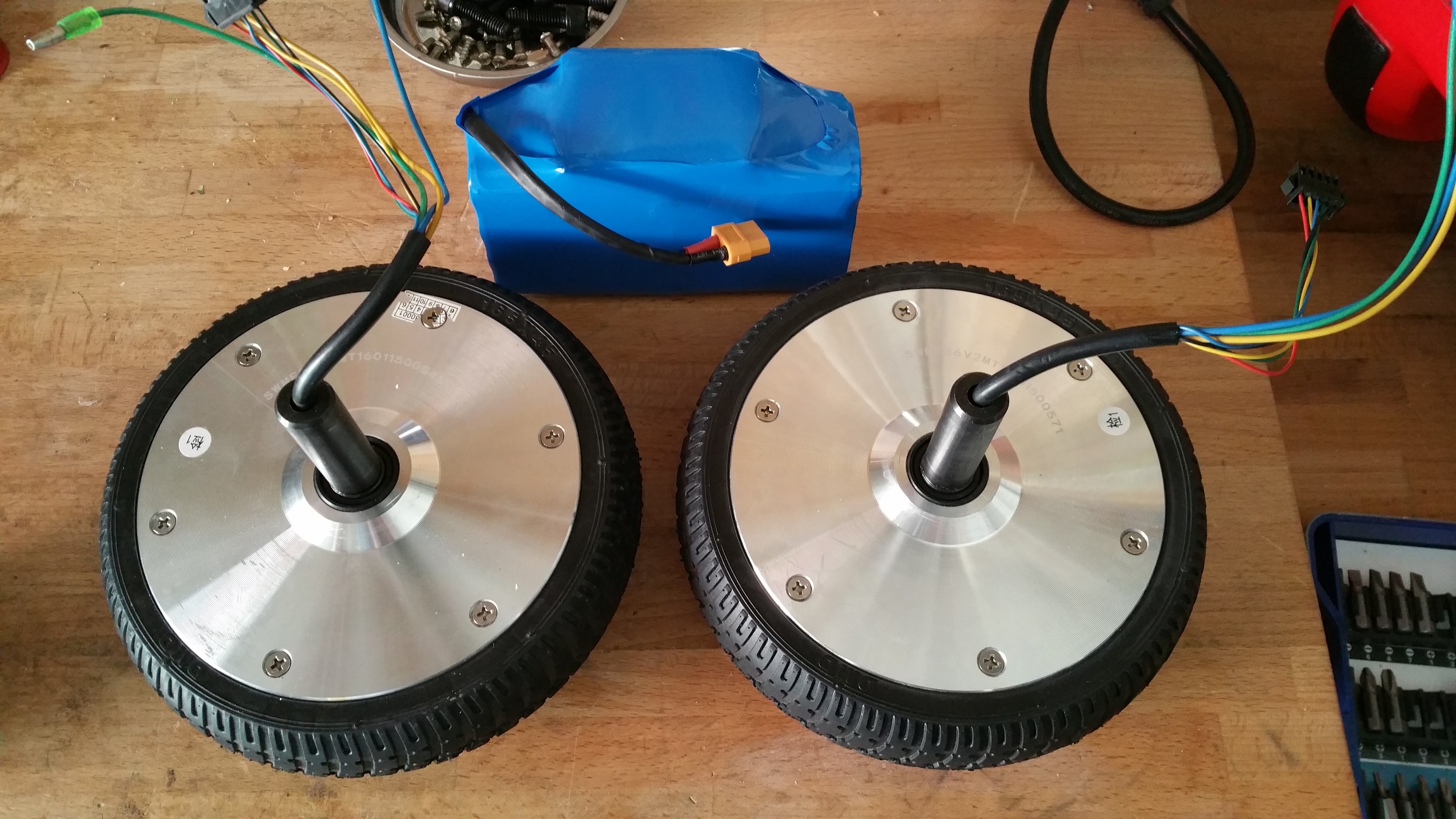
I started out by harvesting the parts from the hoverboard.
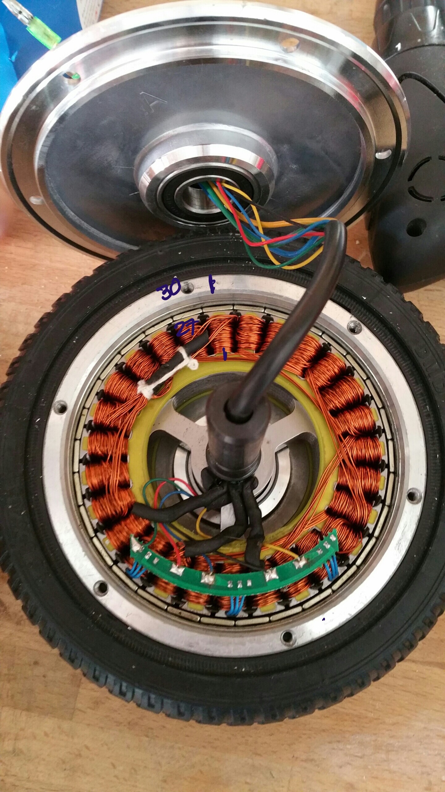
Opening up one of the wheels reveals the 30 poles (30 magnets), 27 coils and 3 hall sensors the motor consist of.
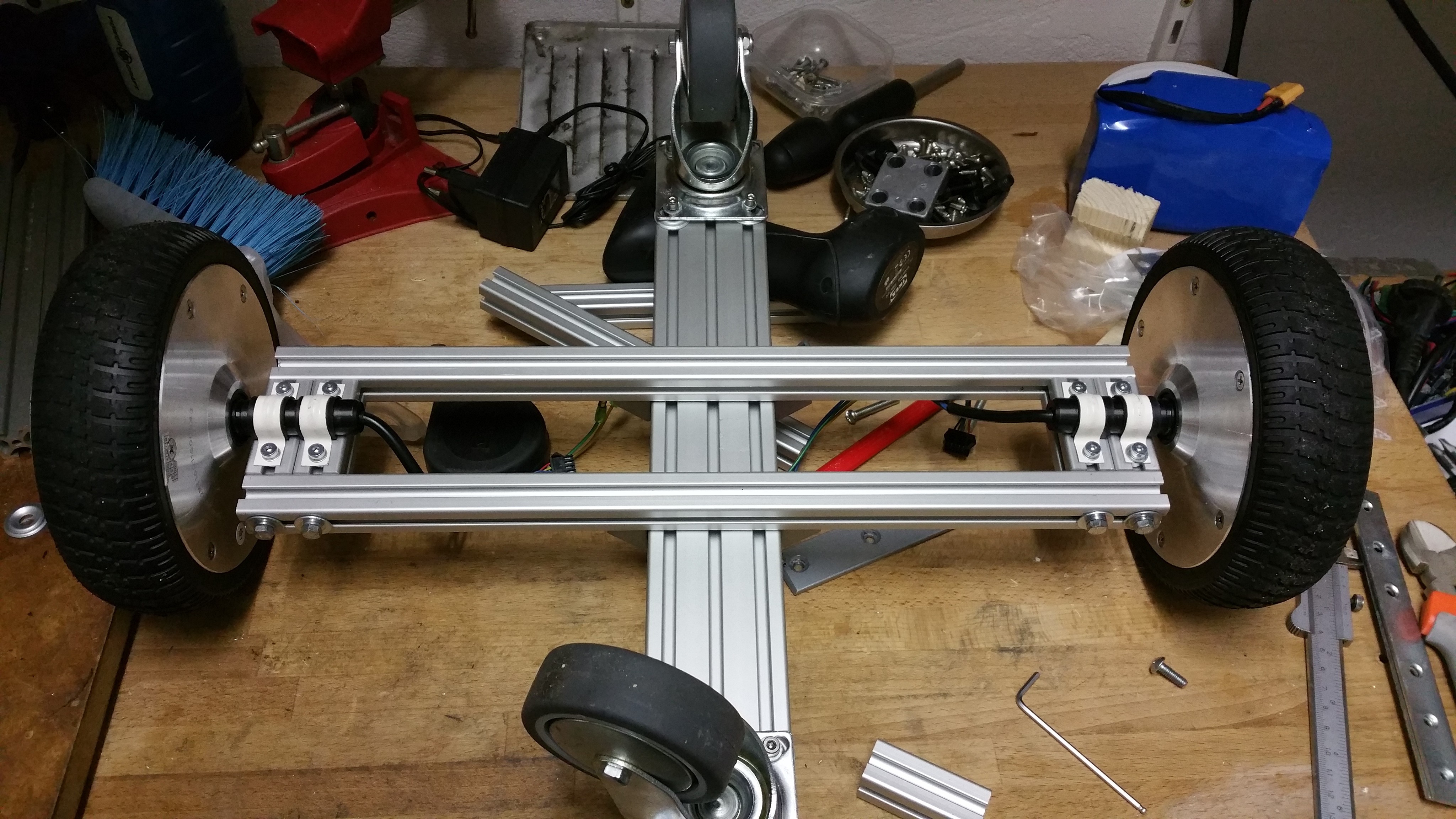
To test this, I created a simple frame to hold the two motors, battery and 2 VESC's.

Note: in the above pictures I used some spacers for the mounting of the caster wheels, but still had too much ground clearance. So later I added a patch of 8mm polyethylene, readily available for cheap as 'chopping board' in a nearby 'Swedish' furniture store.

The video below shows the initial test. The throttle was limited to 40% to get to this low speed. The VESC's were configured in BLDC mode and with hall sensors. The radio received its power from one of the VESC's so the two DC-DC converters visible in the picture were not in use for this test. Note that most of the noise comes from the caster wheels having too much play.
Results were promising, so I could continue with the next step: integrating with ROS.
MORPH : Modular Open Robotics Platform for Hackers
An affordable modular platform for open robotics development for hackers. Provides a jump start to build your own robot.
 Roald Lemmens