 Brian McEvoy
-
1Prologue or "How I came to Love the Pipe"
This is an introduction that briefly describes the process of bringing laser taggers from the back of my mind to something I can hold in my hand. The long, long LOOOONG version can be found on my blog which details every day of the process which took roughly half of 2017.
3D printing seemed like the perfect venue for building a laser tag gun (tagger) and I had been modeling in OpenSCAD for a couple years so I figured I was ready to tackle the task of making a tagger. This was the first design, it was going to be propped up on a sturdy tape gun handle and all the parts inside would be held together with machine screws and bolts. I was okay with the boxy design for a first pass. Unfortunately, the parts became larger than my print bed, which was medium at 200mm and much too big for some of the small printers. Keeping the parts accessible to lots of people was important and I didn't want to exclude someone with a small printer.
Here's the first model infinitely exploding and rotating.
![]()
Every print was flimsy and refused to fit properly. I even tried to add steel keel down the middle which would add some heft and support but it was a losing battle.
This was only first of many road blocks. Remember that tape gun handle I talked about earlier? Well, this wasn't my first attempt at building taggers and one of my earlier attempts involved bolting PVC pipes together in a gun shape. If you have ever worked with round pipes you will know that they do not play nicely with other shapes. This was exactly the reason I abandoned the idea years ago. Nevertheless, I didn't ignore it as a worthy building material. With the failure of the full-printed tagger, it was time to brainstorm for a building material which was rugged, inexpensive, and accessible.
Plumbing pipes! I bet you saw that coming.
A whole new model was started. This time the printed parts would interface between a piece of pipe and the component I wanted to mount. Have you ever seen a switched mounted on an electrical pipe? No. They are always mounted on an electrical box which has flat faces. How many flat faces are on a round pipe? Zero. This wasn't a match made in heaven but modeling 3D parts around the curvature of a pipe would be a plain matter of some basic measurements and math. Now, OpenSCAD was a perfect match.
![]()
My first attempt at laser tag was not entirely unsuccessful. I did program an Arduino to act as a laser tag controller with a basic game mode and everything. Since that time I also grew an appreciation for modularity and where to cut costs and where to spend. At first, the whole system was going to reside on a single Raspberry Pi 0. All the LEDs, switches, and sound would come from it. This wasn't the worst idea but it was abandoned in favor or putting all of the tagger's I/O (inputs and outputs) onto a single Arduino. Arduinos are notoriously easy to find and not as intimidating to beginners as many other microcontrollers. They have a huge community of support and documentation plus they're easy to replace if the tagger falls in the water or takes a nasty hit.For this project, an Arduino Micro Pro was selected because of its easy-to-use serial communication and they connect to many computers without additional downloads. The infrared library by Ken Shirriff has been reliable and used for years by many hackers, myself included. It served as the communication core of the Arduino firmware. The library did need a little tweaking to work with the Micro Pro but I outlined that process here and it's very important.
![]()
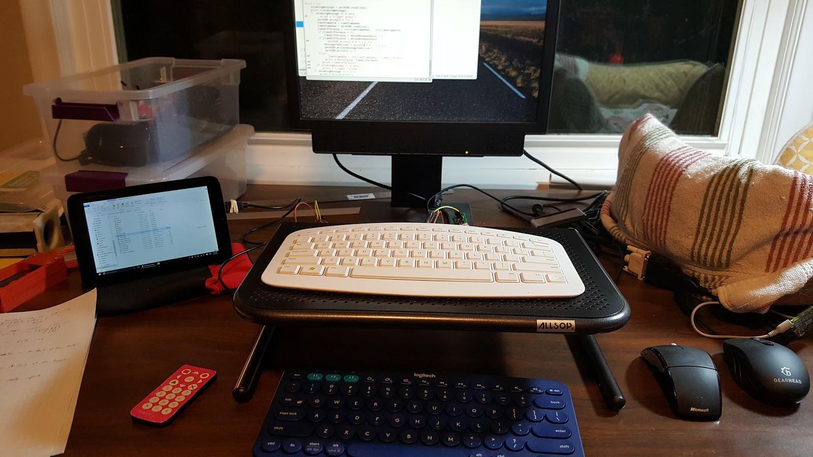
The firmware programmed into the Arduino was revised for a couple weeks until it withstood the onslaught of commands coming from an Arduino serial terminal running on a Windows machine and a Raspberry Pi running a Python script where the game was being built. The beauty was that there was no game data in the Arduino. You could program it to deliver one point of damage or 65,000 points of damage and it didn't know the difference. It was nothing more than a peripheral to the computer which could be Windows, Linux, Android, another Arduino, ESPxxx or any box capable of performing automation through a serial port. Support on multiple operating systems was another benefit of using an Arduino in the tagger.
![]()
It became clear that the Arduino as a firmware-carrying device was the best way to go so a custom printed circuit board (PCB) was designed and ordered. The PCB included a socket for the Arduino rather than integrating the components directly to the board. This was significantly faster to design and it allowed anyone to solder up a control board because it didn't involve any small or fragile components. In fact, the control board uses all insertion mount technology (IMT) components. This is roughly the skill level of a beginner's soldering kit. The PCB is open-source so anyone can make their own edits or order their own batch. There is even a version of the PCB which is easy to print at home if you're inclined to make your own single-side PCB instead of ordering one. It has thicker traces which are easier to transfer which I found to be very important while I screwing up my own homemade boards.
![]()
There was a similar process for the sensor boards which receive infrared signals from opponents but these have small (1206) surface mount technology (SMT) components but they are possible to solder by hand. That was intentional. Source material for these boards is also available. They're single-sided so making them at home is inexpensive and simple, as far as homemade PCBs go.![]()
With the electronics and programming sorted out, I started back on the physical tagger. I took some pride in the design and my in models so each dimension has been deeply integrated and tested. This deep integration with OpenSCAD means that a change to one part doesn't screw up everything else. The parametric nature of OpenSCAD actually makes changes like this simple, if done properly. For example, I used 2" ABS pipe, available at my many hardware stores across the USA. I realize that 2" pipes aren't used in most other countries and if someone were to input the inside radius and outside radius of an equivalent metric pipe those changes would ripple through the rest of the models without much fuss. Maybe none, I haven't tried it.
The final version of the tagger is spinning below. This represents over eight hundred lines of code written over months. Each part can be rendered individually with predictable changes to the code and all the code and models are freely downloadable. OpenSCAD is also open-source and small enough to fit on a flash drive from 2012.
![]() I have a donation link on my blog but what I really want is for people to show their gratitude by building these and exercising and taking pictures of how much fun they're having. If people write their own games it would be spectacular if they shared them with the world. I have notion that strapping a cheap Android phone to a tagger would be one of the world's first laser tag gun with a touch screen and Bluetooth sound. Just sayin'
I have a donation link on my blog but what I really want is for people to show their gratitude by building these and exercising and taking pictures of how much fun they're having. If people write their own games it would be spectacular if they shared them with the world. I have notion that strapping a cheap Android phone to a tagger would be one of the world's first laser tag gun with a touch screen and Bluetooth sound. Just sayin' -
2Control board
The first control board for this project was a simple protoboard with components soldered to the face which followed a circuit schematic. This could have been repeated for every tagger but the process would have been laborious, especially when making numerous boards, one for each of my friends. If only two boards were being produced, this would have been the obvious choice. Instead, a custom board was designed with EasyEDA, which received a positive review on Hack a Day. EasyEDA also allows anyone to freely view this PCB, branch their own copy for changes and order copies. Here is a link to the project page for the control board. This does not include the sensor boards which will be linked in a different step.
![]()
It is possible to make a protoboard version with only the above schematics and the necessary components. No one is required to order the boards from EasyEDA and I don't get any of that money so I don't mind whichever way people choose. On the project page, there is also a layout called "PiTagErrUs_MCU_Single-Layer_Homemade" which was made for people who want to make their own PCBs at home. I used this when making toner-transfer boards. The traces are thicker and have more clearance but the footprint for the transistors may be messed up. I recommend ordering the version called "PiTagErrUs_MCU_Single-Layer" which is what is pictured in the rest of the steps. Here is a picture of one of my toner-transfer boards, left, next to the board printed by EasyEDA.
![]()
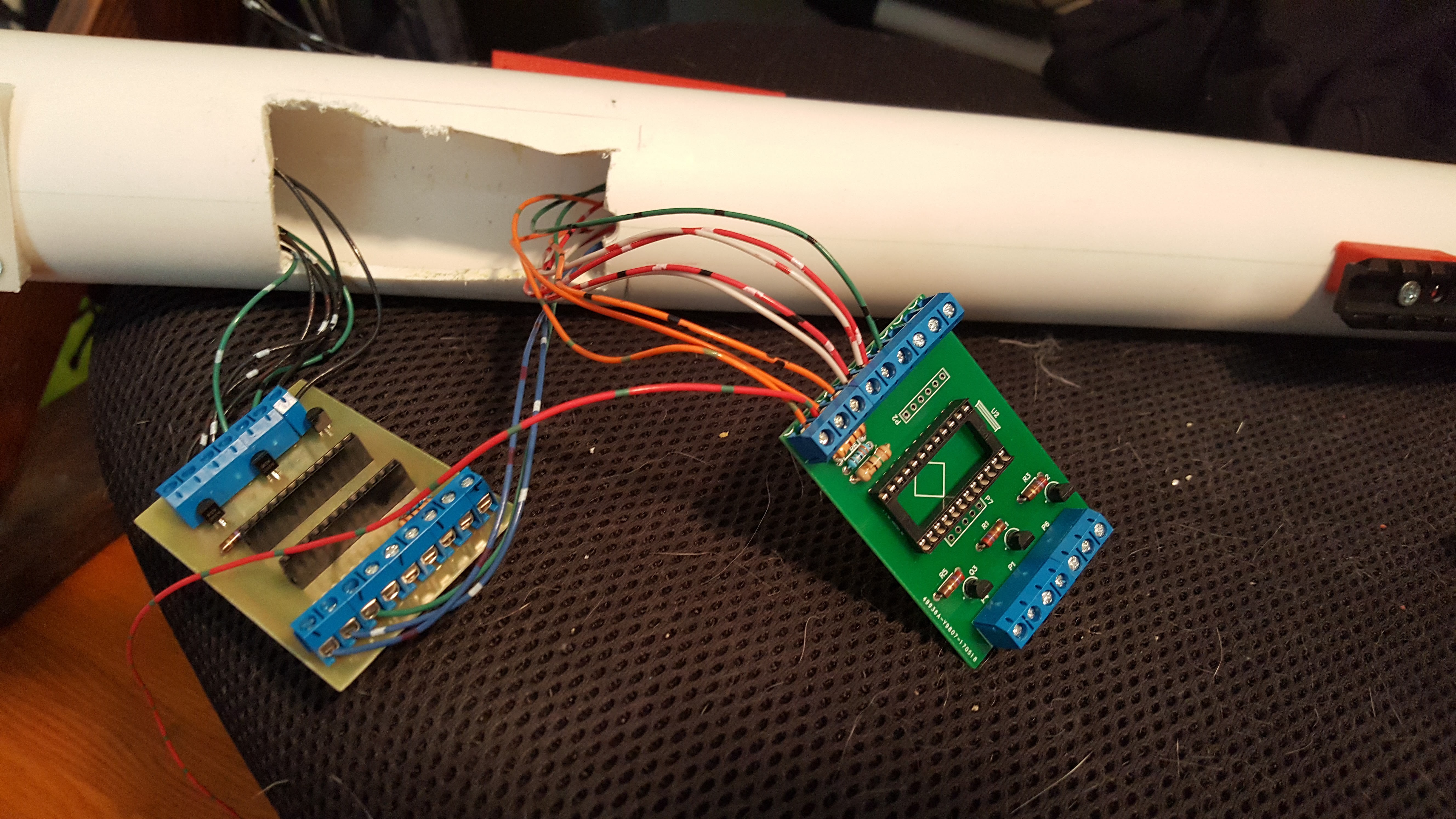
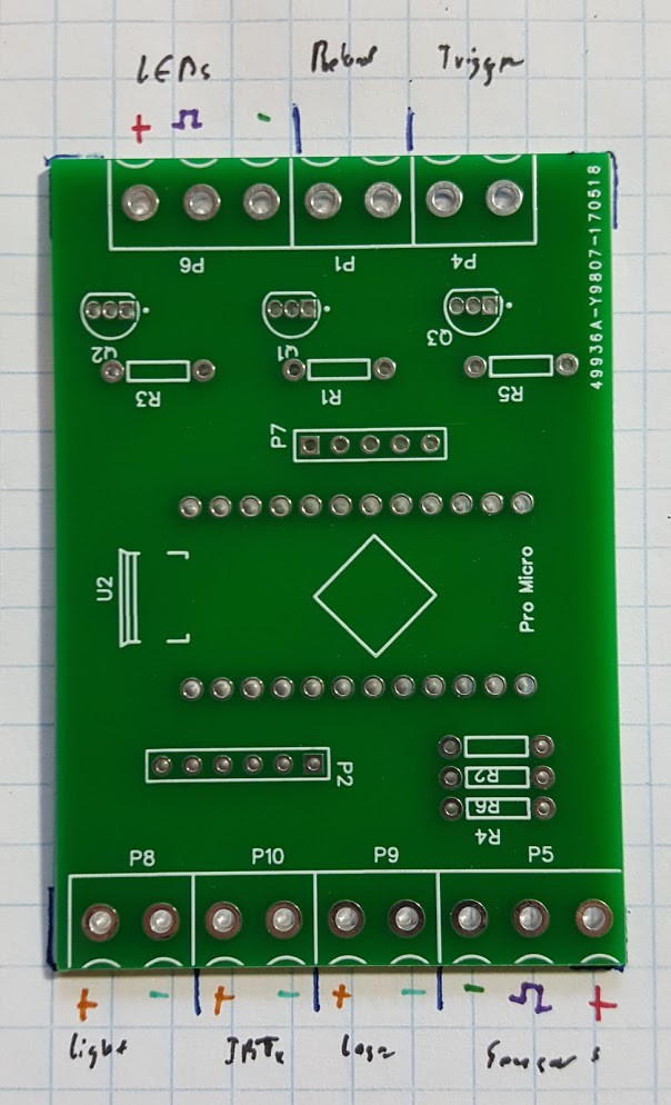
A quick reference guide was included below which shows the exact connections for each component. The idea was that all the amplification would be done on this central board which has a socket for the Arduino Micro Pro. Wires would be run to the control board and tightened under screw terminals. With the screw terminals and Arduino attached, the board fits nicely inside the pipe.
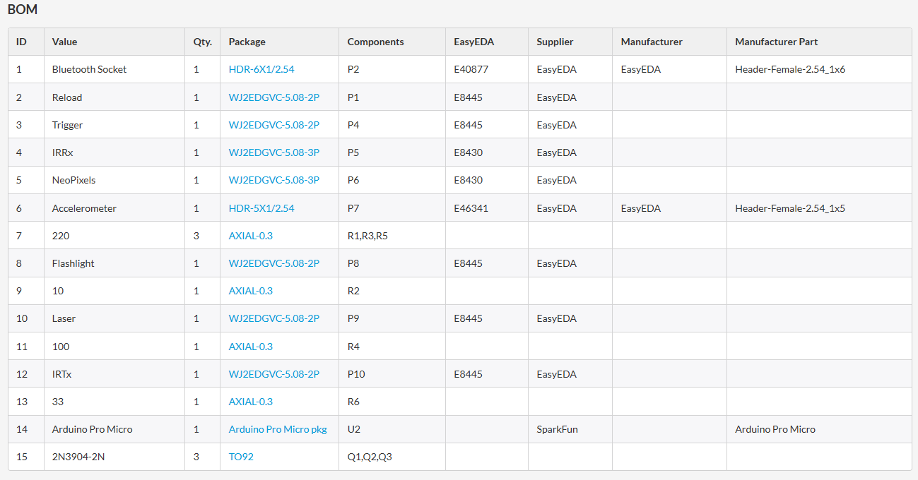
The component sizes are shown on the bill of materials (BOM) below which was taken from the the project page.![]()
![]()
-
3Sensor boards
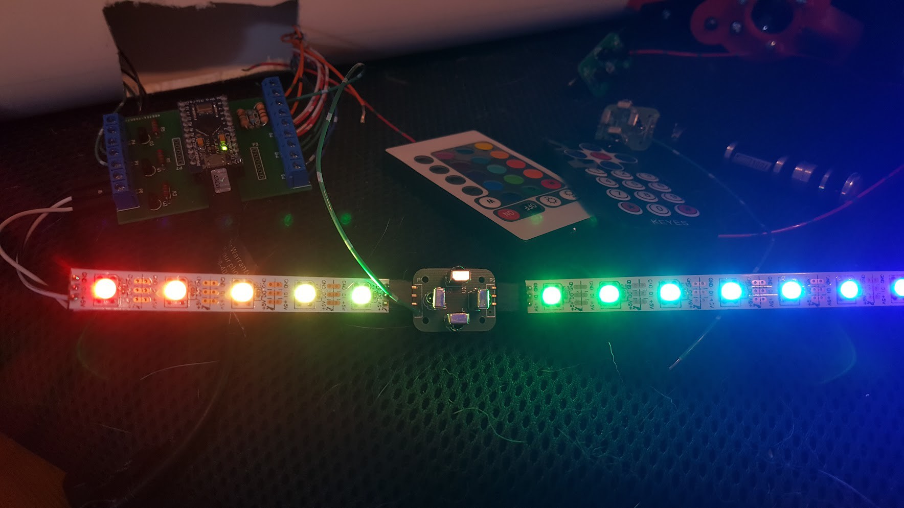
Sensor board project page on EasyEDA. When I ordered these boards I ordered 100pcs at a time. They are very versatile in where they can be placed. They were designed to be put inline with individually addressable LED strips. These strips carry 5V power and designate team color so any place where lights can be seen can be made into a target for opponents. These sensors can be used right on the tagger or placed on a hat or vest. The lights aren't necessary, they just need power from the controller board and the signal wire from the sensor board needs to go back to the control board.
Up to four infrared sensors can be installed on each board and only one is necessary.
![]()
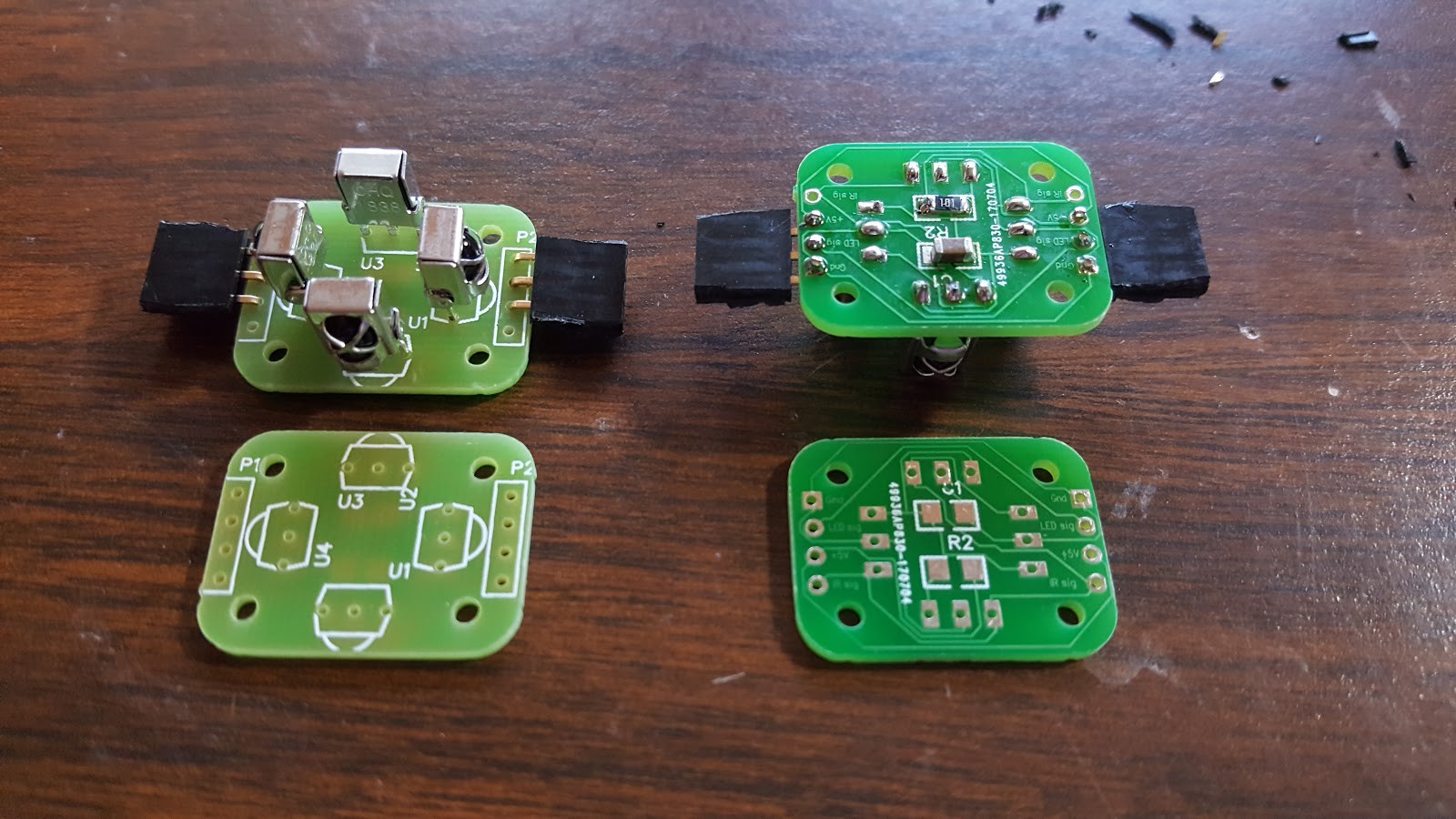
These boards are single-sided so it's another easy one to make at home but there are 1206 (small surface mount) components but I've already soldered these by hands without trouble or even a magnifying glass. I have good eyes though.![]() The original design had an addressable LED right on the board but that
added unnecessary complexity if lights are nearby anyway. These boards
can be placed at the beginning or end of and LED strip or even inline
since they have pass-through traces. In fact, since most flexible light
strips have adhesive on the back so an inline sensor can be mounted
without any additional work but they have four screw holes if they need
to be secured.
The original design had an addressable LED right on the board but that
added unnecessary complexity if lights are nearby anyway. These boards
can be placed at the beginning or end of and LED strip or even inline
since they have pass-through traces. In fact, since most flexible light
strips have adhesive on the back so an inline sensor can be mounted
without any additional work but they have four screw holes if they need
to be secured.![]()
-
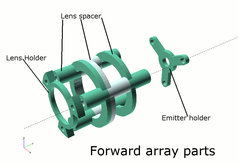
4Forward array
![]()
The forward array is the "business end" of the tagger. It is the most complex part with the tightest tolerances. A lot of work went into making this piece work. Plus, I like the way it looks.
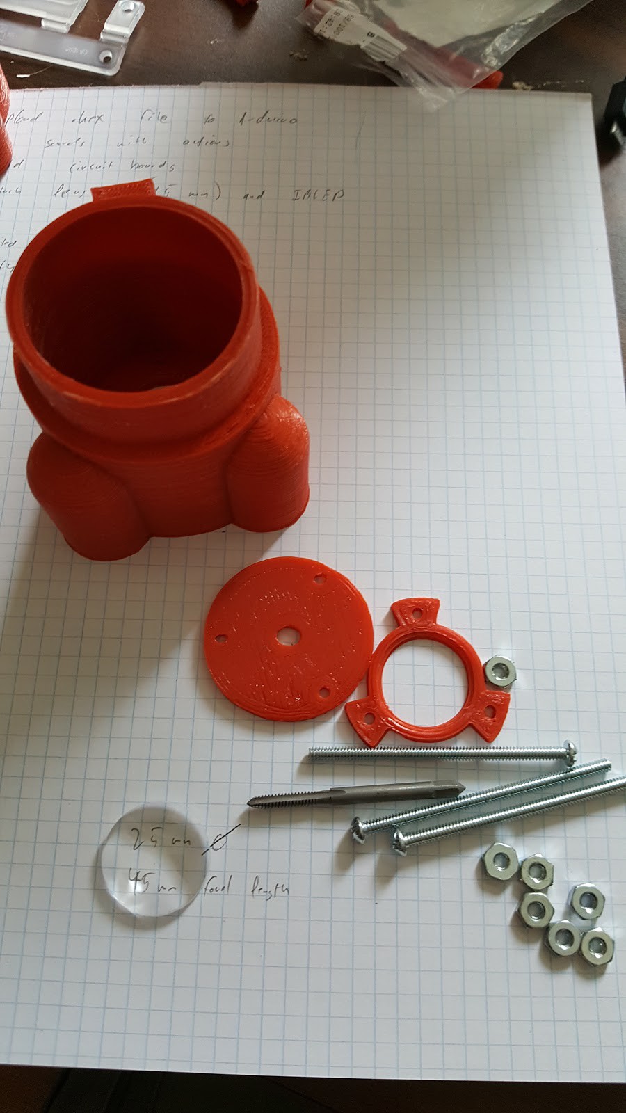
Since I started this project I knew this piece would always be printed with red filament. Orange would also have worked. A red or orange tip means that the gun is not real. Even though these taggers are clearly not firearms, there's no point in scaring people when the alternative is as easy as printing red parts. Plus, red parts on a black tube look cool.
The lens was intended for Google Cardboard. The popularity of that device meant that the lens were available from many online retailers for very cheap. Each lens is optical quality and easy to replace so they were the perfect choice for this project.
![]()
The 45mm focal length of the lens was a nice round number. Three identical 15mm spacers were modeled and printed with a base ring so they form a cage. This cage keeps stray wires from coming between the emitter, mounted on the 3-point star-looking piece. The hole in the middle of the star is for a 5mm LED clip. The winged ring at the other end holds the lens against the forward array which isn't show in the picture below.
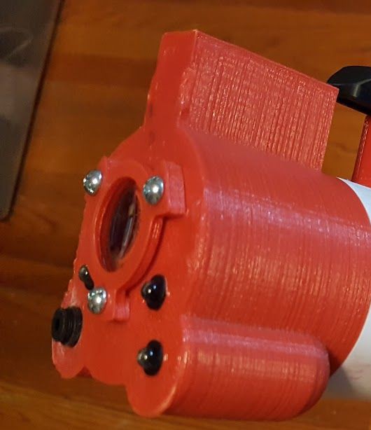
![]()
When assembled, the forward array should look this this from the outside. The arrangement of the LEDs is a matter of preference, I put the two flashlight LEDs on the left side of the face and I keep the red LED and laser on the left. An infrared sensor can also be glued to front of the tagger but this is purely optional. There's plenty of room and an exit hole for the wires if you choose to do this.
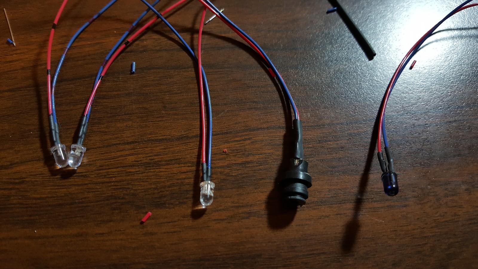
![]()
Each component in the forward array should be given enough wires to reach the control board. I like to solder longer-than-necessary wires to each part then trim them to an appropriate length. Since I haven't talked about how and where to mount the control board it is probably best to keep the wires long. At least 12" or 30cm.
![]()
-
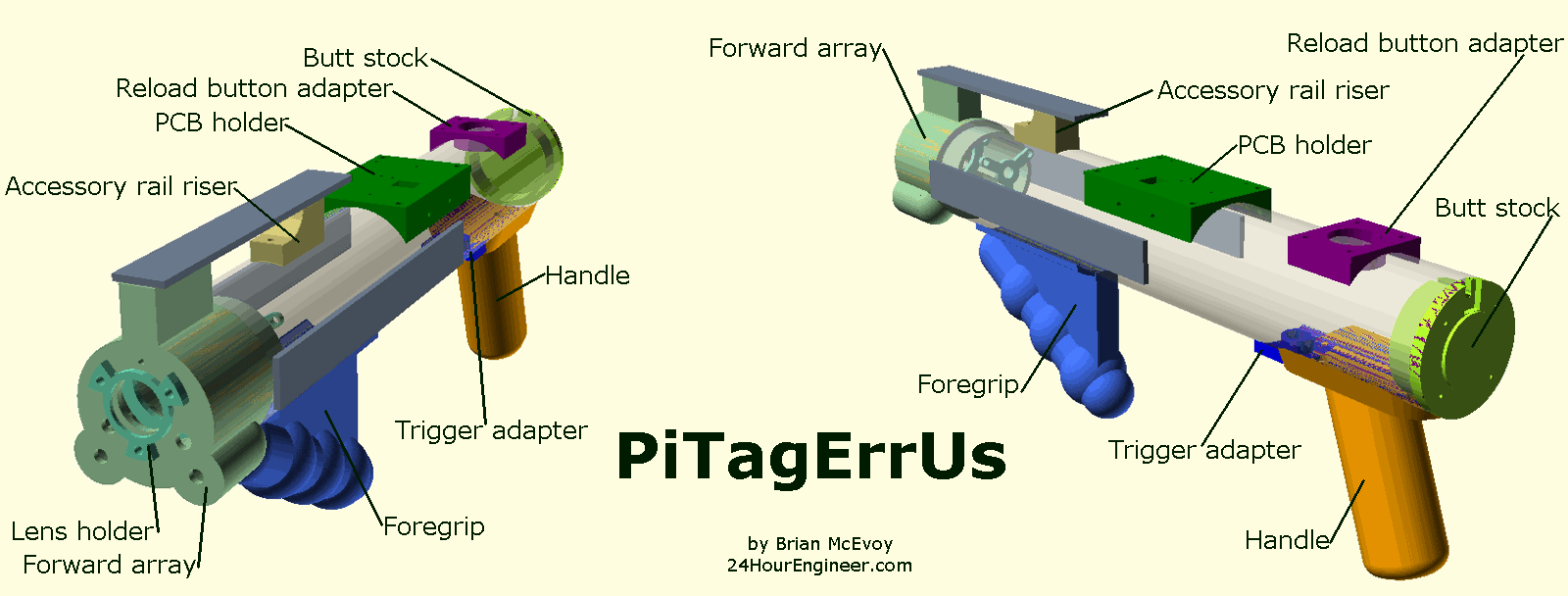
5Back end
![]()
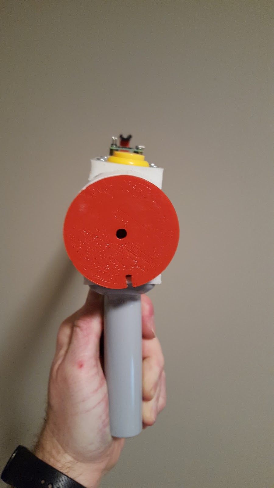
The front end of the tagger is for your opponents. The back end of the tagger is for the operator.
There are no debugging features explicitly built into the tagger so there are no hidden buttons or secret switches. The trigger and reload button are the primary ways players interact with their taggers. If special debugging functions are desired, they can, and should be programmed into the controlling computer. It would certainly be possible to enter a debugging mode by pressing the trigger and reload button together for three seconds or using Morse code to type SOS.
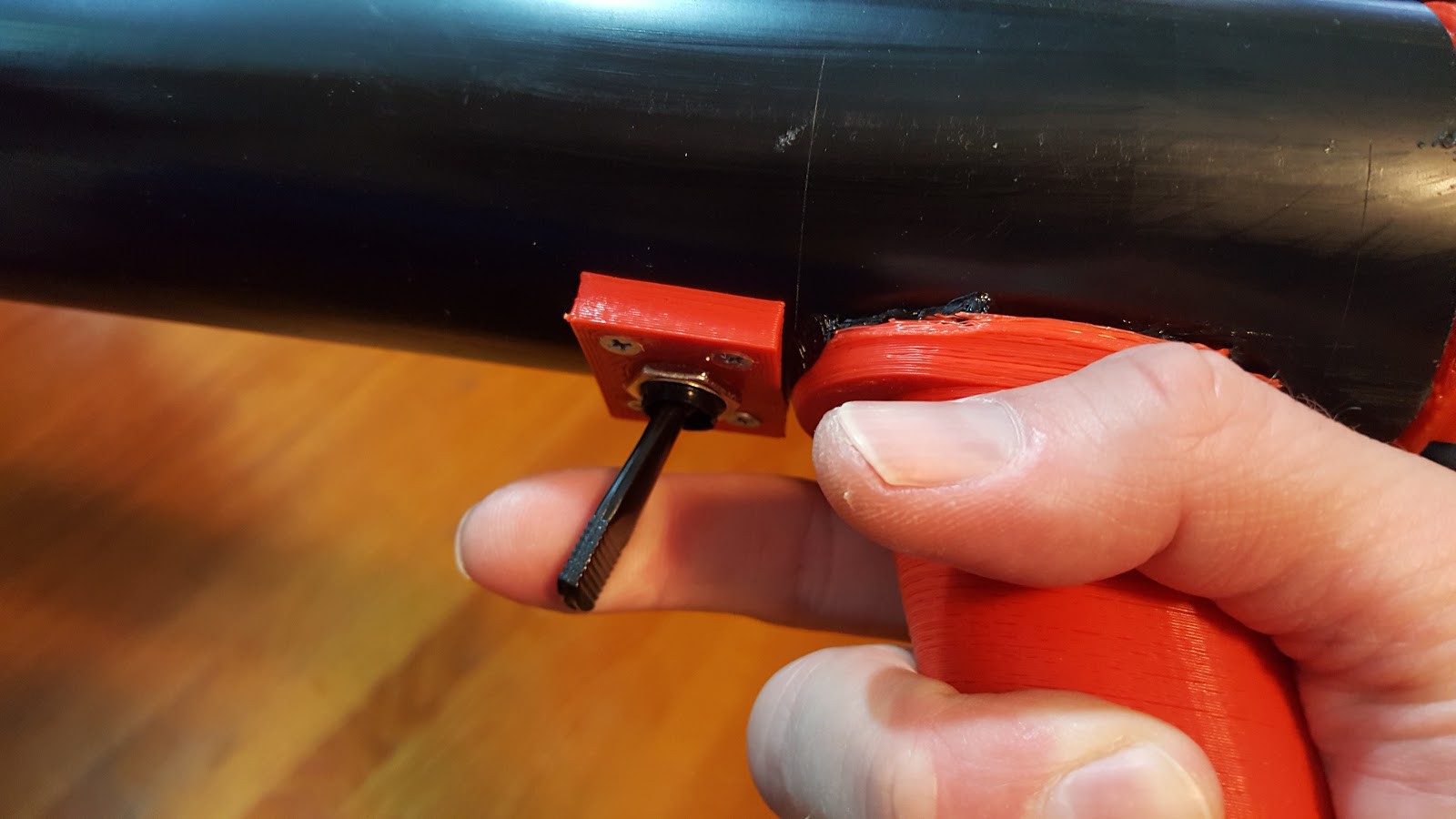
The reload button is an automotive switch. Many auto parts stores stock them but they're unusual. It is a momentary toggle switch, sometimes called a spring-return paddle switch or some permutation of those words. They act as a great trigger when you flip them upside-down with a clicky feel. If you search for "Dorman 85958" you can find them online but they're more expensive than auto part stores.
![]()
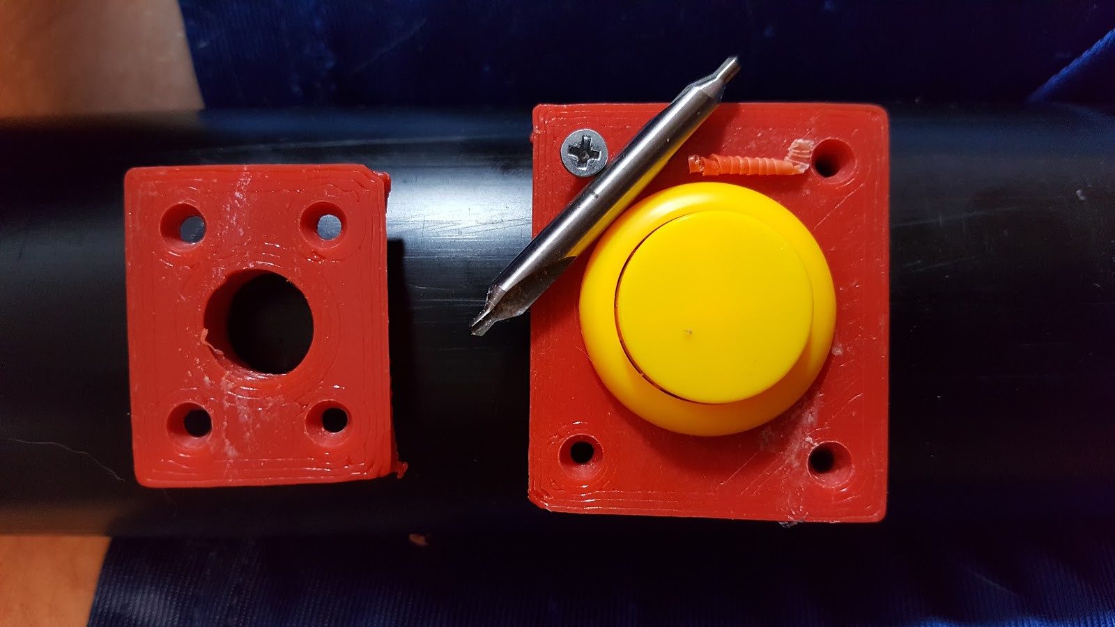
The reload button is an arcade button. These also have a satisfying click when pressed but they are substantially less expensive than the automotive toggle switch. Approximately 10:1 so it never hurts to have a few arcade buttons on hand for this, or other projects. Personally, I love these buttons because they're big, bright and durable.
![]()
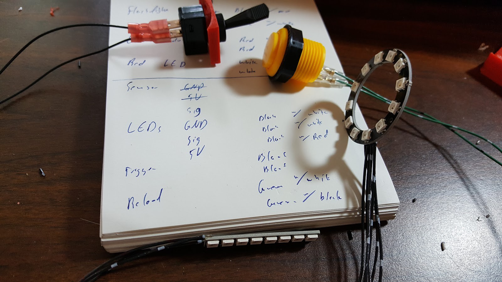
Wiring for the button and switch can be done with a soldering iron and shrink tube but a crimping tool and crimped terminals are my preferred method. The current options for lights usually require soldering.
![]()
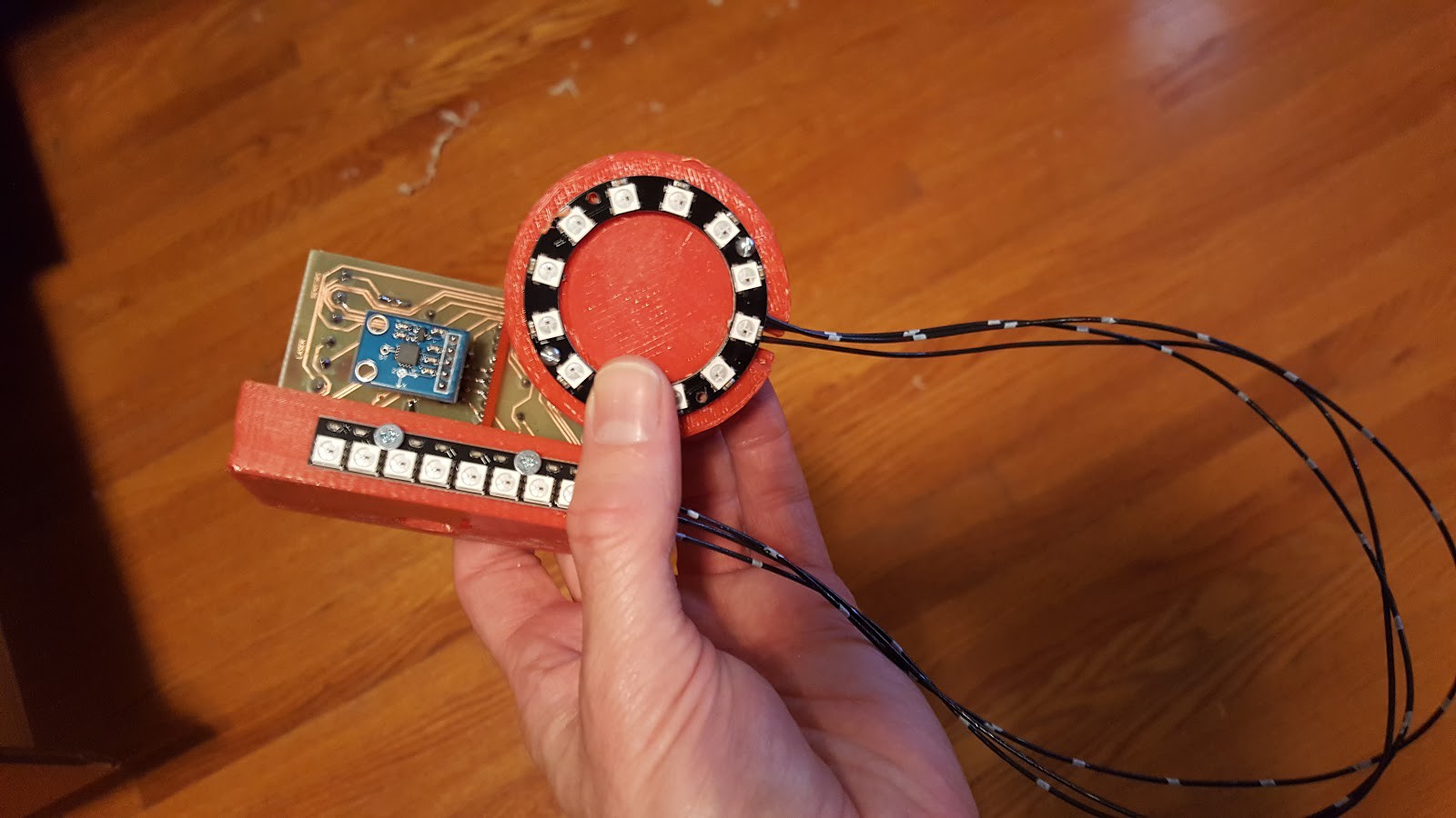
Lights for the back end have some options. The 12-LED ring shown below fits neatly over the hemisphere of the butt stock. There are mounting holes in the butt stock which line up with the mounting holes in the LED ring and even a cavity for where the wires are soldered to the ring. Alternatively, you can buy a lot of individually addressable LED strip lighting. These are often called NeoPixels which was coined by Adafruit.
The first twelve LEDs are easy to control through the computer and intended as status indicators for the player. Logically, they could indicate a player's health, or ammo or game time. Or a combination of those since the colors can be chosen by the controlling computer. After those twelve LEDs, all the rest are changed by a single variable since these LEDs were meant to indicate team color. In the demo program, the player's color is determined by a signal from the remote and that is also the team. If the player is assigned to red team, their tagger's LEDs will be red until the tagger is hit by another team, maybe blue, at which point the tagger will turn blue for a moment.
![]() The PCB holder has a lot attached to it. On the inside is the controller board and Arduino. To keep the board in place, the small fingers hold the board and a couple holes hidden in the fingers allow zip ties to wrap around the board and PCB holder. On the outside is the hole pattern for a Raspberry Pi 0 or Raspberry Pi 0 Wireless. There are mounting holes along the sides to add 8-bit addressable LED strips. These could be used as the primary tagger color LEDs or just used in conjunction with other LEDs strips on the tagger. When assembled, the square hole should line up with the USB port of the Arduino so a USB cable can be run to it.
The PCB holder has a lot attached to it. On the inside is the controller board and Arduino. To keep the board in place, the small fingers hold the board and a couple holes hidden in the fingers allow zip ties to wrap around the board and PCB holder. On the outside is the hole pattern for a Raspberry Pi 0 or Raspberry Pi 0 Wireless. There are mounting holes along the sides to add 8-bit addressable LED strips. These could be used as the primary tagger color LEDs or just used in conjunction with other LEDs strips on the tagger. When assembled, the square hole should line up with the USB port of the Arduino so a USB cable can be run to it.
![]() These parts were modeled around inexpensive parts readily available but there is still a lot of room for improvisation. The PCB holder is flat on the outside so an Android phone could be strapped there instead of the Raspberry Pi. Any arrangement of holes could be drilled there to accommodate a similarly-sized single-board computer like the Orange Pi or even a LattePanda with some overhang.
These parts were modeled around inexpensive parts readily available but there is still a lot of room for improvisation. The PCB holder is flat on the outside so an Android phone could be strapped there instead of the Raspberry Pi. Any arrangement of holes could be drilled there to accommodate a similarly-sized single-board computer like the Orange Pi or even a LattePanda with some overhang.
![]()
-
6Pipe construction
![]()
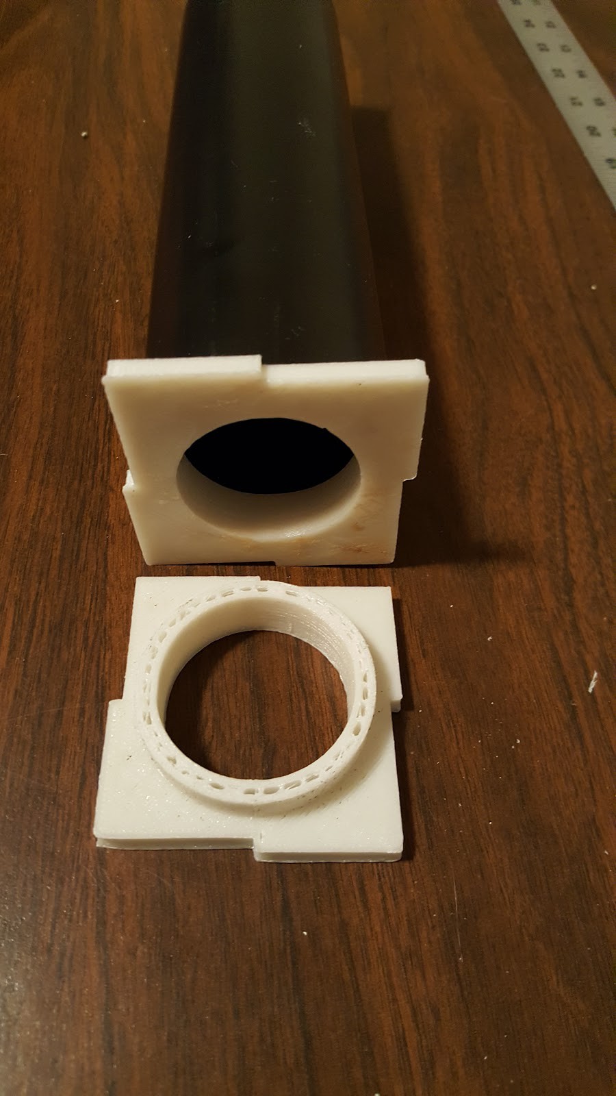
Proper alignment of the parts was a huge difficulty. It seemed like it would be an easy task to line up the parts on the top with the parts on the bottom. After all, the trigger should be right in line with the handle or it won't feel proper. Once an early tagger was assembled without any aid or measurements it became painfully clear that something needed to be designed in order to properly line everything up.
![]()
Two plugs were printed which fit snugly into the ends of the pipe. These plugs, once aligned would hold a straight-edge so that a center line could be drawn on both sides of the pipe. The pipe could actually be divided into quadrants if there was desire to attach more accessory rails. Detailed instructions for the pipe marking can be found on the blog if something isn't obvious.
![]()
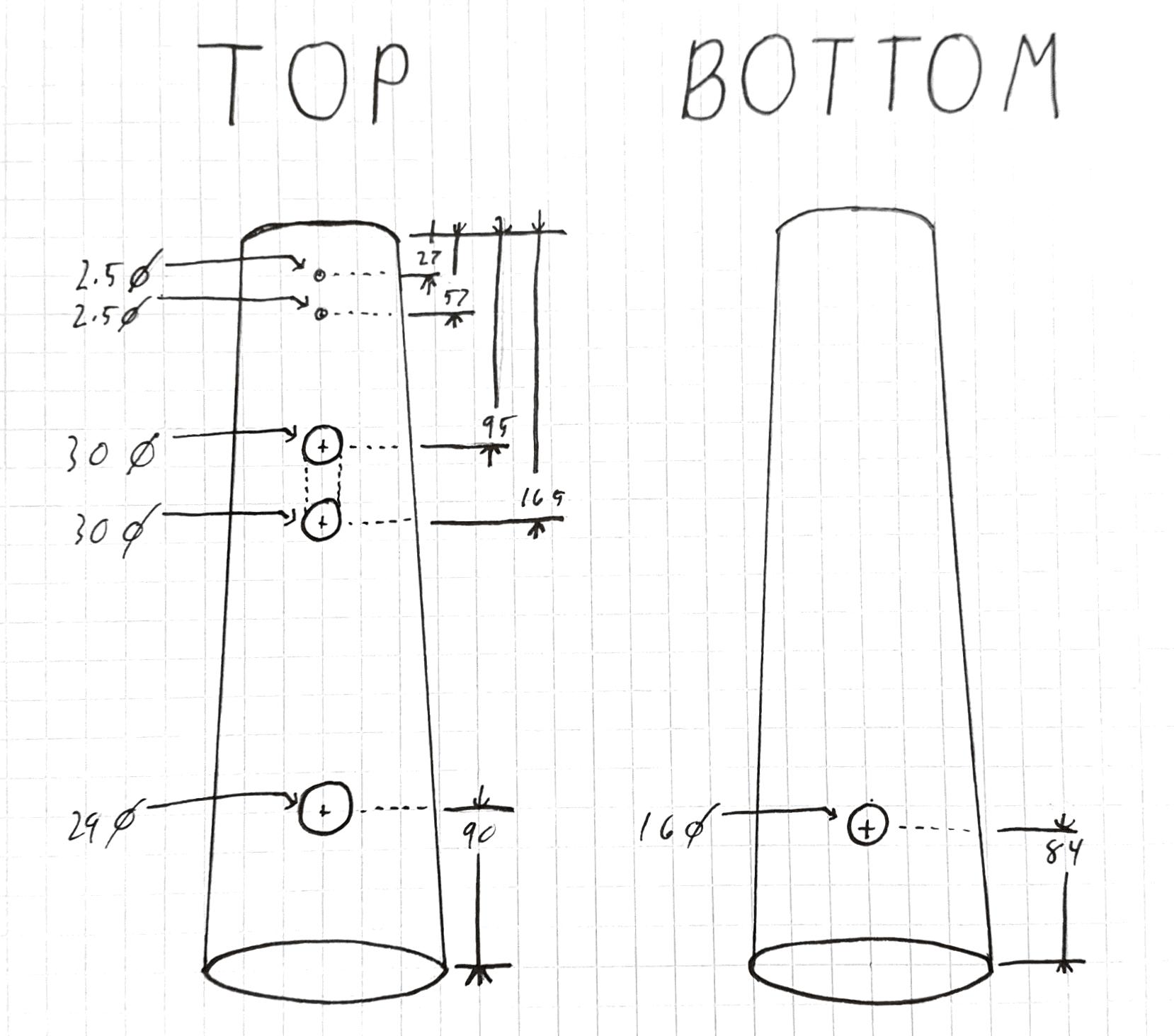
Once the center lines have been marked on the pipe, it is time to mark all the hole locations. The following diagram shows where to drill each hole and what size it should be. A stepping drill bit or "unibit" is highly recommended for any hole over 1/4" (6mm). I also recommend clearly marking the front and back of the tagger so there is no confusion about which hole is being marked.
Two of the holes on the bottom are linked with dashed lines. These lines should be cut in order to make one long hole. This is where the PCB holder will go and this allows the control board to fit into the pipe.
![]()
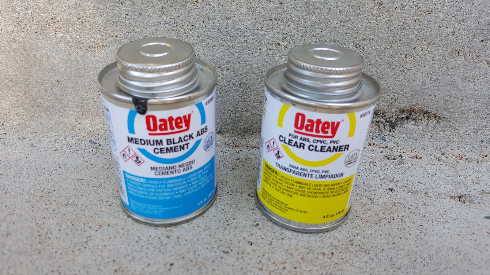
Two of the printed parts are meant to be glued to the pipe. ABS pipe and ABS printed parts go together nicely with ABS cement. Pictured below are the two cans I used but any reputable brand will work well. Follow the directions on the cans. The cleaner may not be strictly necessary for good adhesion but I use it for removing scratches on the ABS and polishing it.
![]()
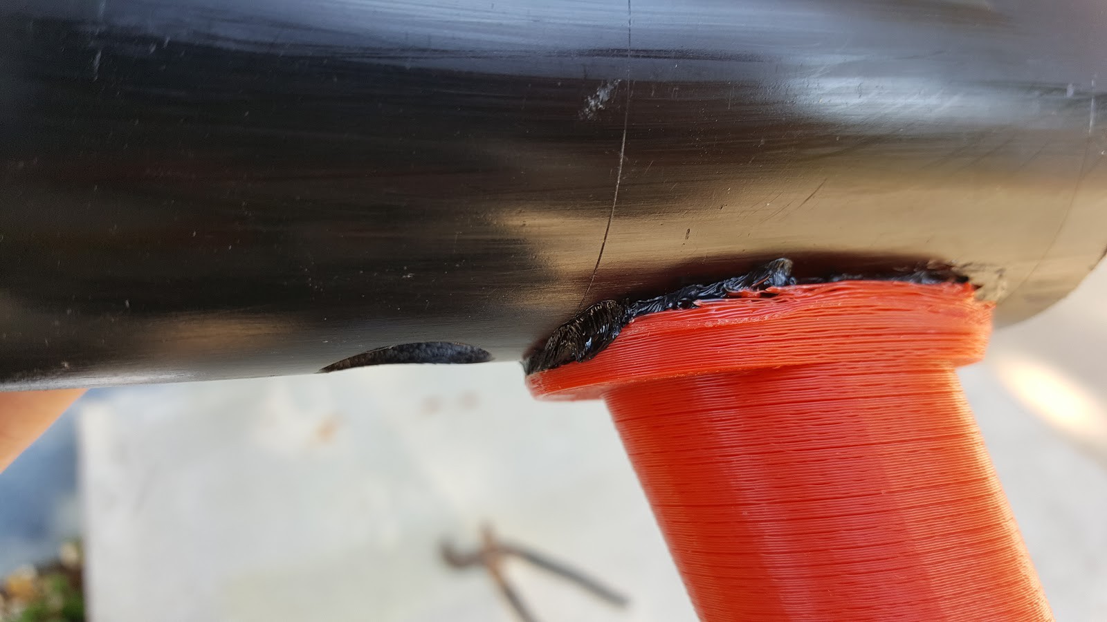
The handle and foregrip should be carefully aligned and liberally cemented to the pipe. The cement is thick and good at getting into the the strands of the 3D printed parts.
![]() All the parts can be mounted and connected. At this point you can get a feel for the tagger and, if you're like me, you will probably make *pew pew pew* sounds at the nearest domestic animals. They will not be as amused as you.
All the parts can be mounted and connected. At this point you can get a feel for the tagger and, if you're like me, you will probably make *pew pew pew* sounds at the nearest domestic animals. They will not be as amused as you.
![]()
-
7Programming
The Arduino Micro Pro doesn't like to play with [Ken Shirriff]'s infrared library.
[Link]
Follow the instructions for installing this library.
Once the library is installed, it must be modified to work our hardware. This troubled me and I followed forums all over in order to figure out what to do. It's a simple matter of changing a couple lines in the library so it uses a pin on the Micro instead of one of the unused pins from the microcontroller. Lines 87 and 89 from the boardsdef.h files need to be swapped so one is commented and the other is not.
If that doesn't make sense follow my blog post which goes into greater detail.
[Link]
![]() The Python code is available in the links for this project. That should be straight forward. Run this program when you want to play laser tag. Set the Pi to automatically run the program at startup and you don't even need a screen. [Al Williams] did a nice write-up regarding running commands in Linux.
The Python code is available in the links for this project. That should be straight forward. Run this program when you want to play laser tag. Set the Pi to automatically run the program at startup and you don't even need a screen. [Al Williams] did a nice write-up regarding running commands in Linux.[Link]
![]()
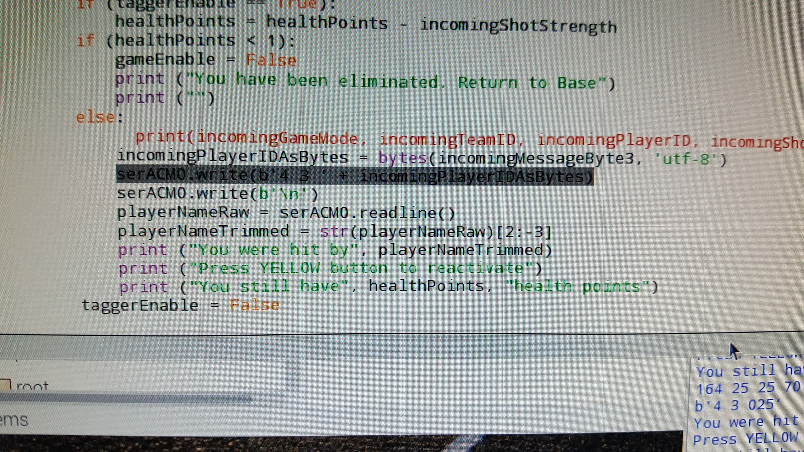
Once these two piece of silicone are talking over the copper of a micro USB cable you have yourself a tagger capable of playing a last-man-standing game where each person can take five hits before they are out of the game.
When you're ready to step it up a notch, program your own game in Python and of course, share it with us!
PiTagErrUs
Transform a piece of plumbing pipe into a rugged laser tag gun.


 I have a donation link on
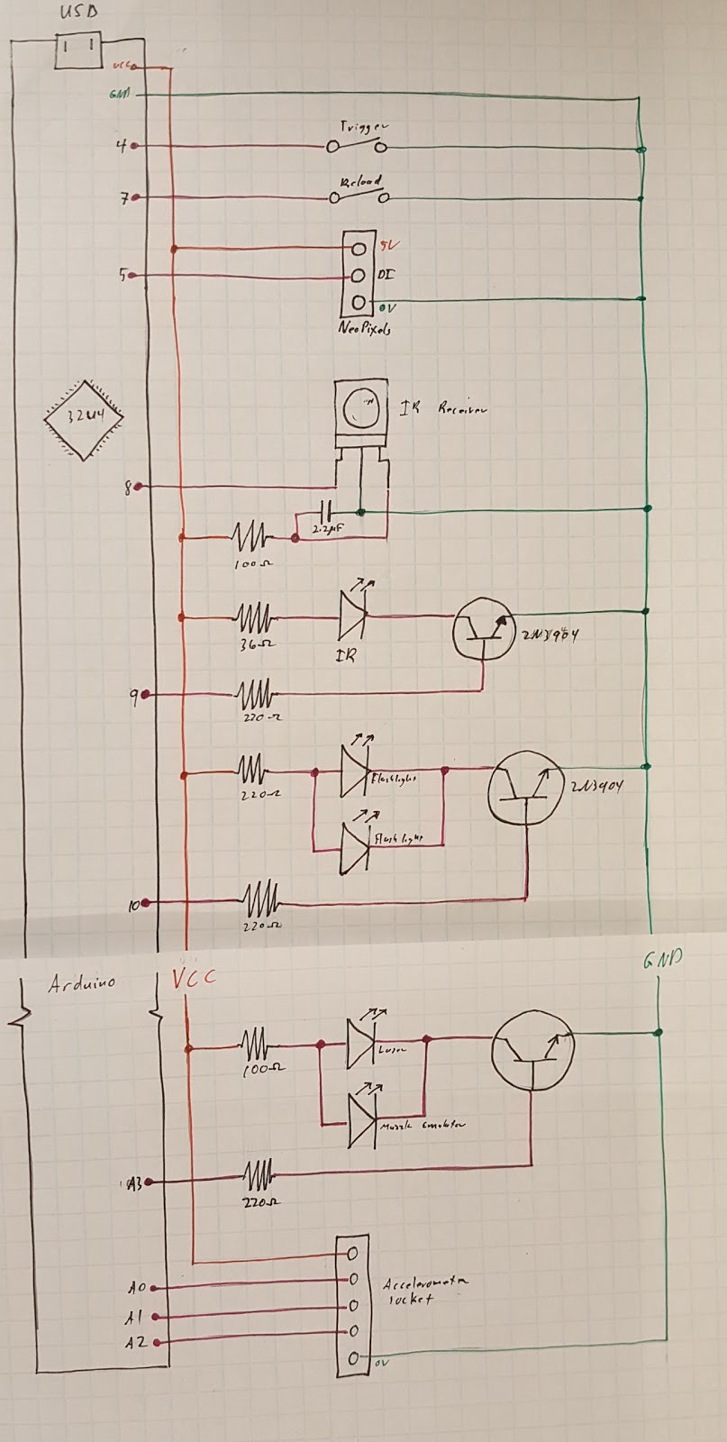

 The PCB holder has a lot attached to it. On the inside is the controller board and Arduino. To keep the board in place, the small fingers hold the board and a couple holes hidden in the fingers allow zip ties to wrap around the board and PCB holder. On the outside is the hole pattern for a Raspberry Pi 0 or Raspberry Pi 0 Wireless. There are mounting holes along the sides to add 8-bit addressable LED strips. These could be used as the primary tagger color LEDs or just used in conjunction with other LEDs strips on the tagger. When assembled, the square hole should line up with the USB port of the Arduino so a USB cable can be run to it.
 These parts were modeled around inexpensive parts readily available but there is still a lot of room for improvisation. The PCB holder is flat on the outside so an Android phone could be strapped there instead of the Raspberry Pi. Any arrangement of holes could be drilled there to accommodate a similarly-sized single-board computer like the Orange Pi or even a LattePanda with some overhang.

 All the parts can be mounted and connected. At this point you can get a feel for the tagger and, if you're like me, you will probably make *pew pew pew* sounds at the nearest domestic animals. They will not be as amused as you.
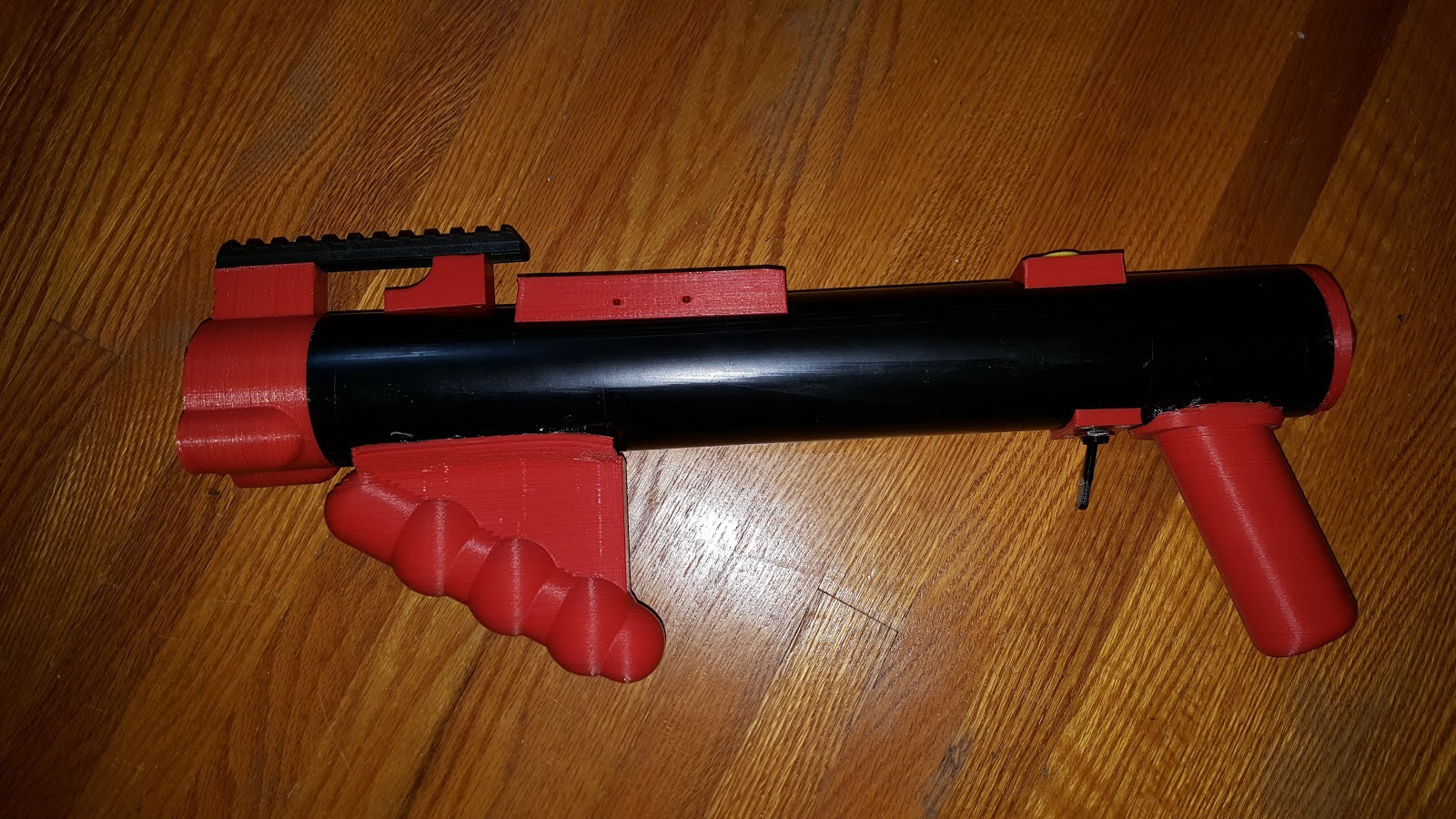
Discussions
Become a Hackaday.io Member
Create an account to leave a comment. Already have an account? Log In.