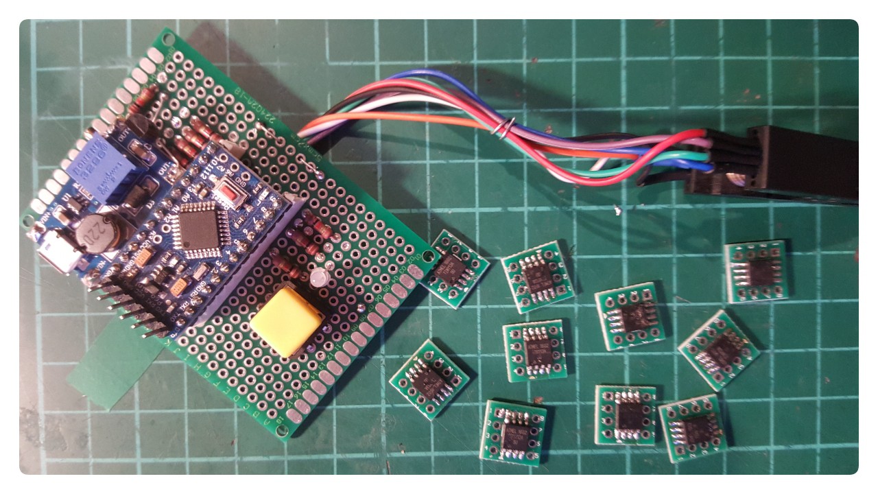
to fix almost all my tiny13a's I had to build this, but it definitely fixed all 10 boards :) for the tinies you don't need any parallel connections, so it's basically SPI + 12V on reset. I've hooked up a boost converter, added a button and "some" LEDs (bicolor), worked them in the code and now basically have a "power on and fix" stand alone fuse resetter for soic Attinies. That's not highly specialised at all. BUT IT WORKS AND THEY WORK! Now I need to clean up my desk.
http://www.engbedded.com/fusecalc/
https://arduinodiy.wordpress.com/2015/05/16/high-voltage-programmingunbricking-for-attiny/

// AVR High-voltage Serial Fuse Reprogrammer
// Adapted from code and design by Paul Willoughby 03/20/2010
// http://www.rickety.us/2010/03/arduino-avr-high-voltage-serial-programmer/
// Fuse Calc:
//   http://www.engbedded.com/fusecalc/
// slightly edited by davedarko in 2017

#define  RST     13    // Output to level shifter for !RESET from transistor
#define  SCI     12    // Target Clock Input
#define  SDO     11    // Target Data Output
#define  SII     10    // Target Instruction Input
#define  SDI      9    // Target Data Input
#define  VCC      8    // Target VCC

#define  BUTTON   3    // Target VCC
#define  LED_RED  7    // Target VCC
#define  LED_GRN  5    // Target VCC

#define  HFUSE  0x747C
#define  LFUSE  0x646C
#define  EFUSE  0x666E

// Define ATTiny series signatures
#define  ATTINY13   0x9007  // L: 0x6A, H: 0xFF             8 pin
#define  ATTINY24   0x910B  // L: 0x62, H: 0xDF, E: 0xFF   14 pin
#define  ATTINY25   0x9108  // L: 0x62, H: 0xDF, E: 0xFF    8 pin
#define  ATTINY44   0x9207  // L: 0x62, H: 0xDF, E: 0xFFF  14 pin
#define  ATTINY45   0x9206  // L: 0x62, H: 0xDF, E: 0xFF    8 pin
#define  ATTINY84   0x930C  // L: 0x62, H: 0xDF, E: 0xFFF  14 pin
#define  ATTINY85   0x930B  // L: 0x62, H: 0xDF, E: 0xFF    8 pin

void setup() {
  pinMode(BUTTON, INPUT_PULLUP);
  pinMode(LED_GRN, OUTPUT);
  pinMode(LED_RED, OUTPUT);

  pinMode(VCC, OUTPUT);
  pinMode(RST, OUTPUT);
  pinMode(SDI, OUTPUT);
  pinMode(SII, OUTPUT);
  pinMode(SCI, OUTPUT);
  pinMode(SDO, OUTPUT);     // Configured as input when in programming mode
  digitalWrite(RST, HIGH);  // Level shifter is inverting, this shuts off 12V
  Serial.begin(19200);
}

void loop() {
  digitalWrite(LED_GRN, HIGH);
  digitalWrite(LED_RED, LOW);

  if (digitalRead(BUTTON) == LOW)
  {
    digitalWrite(LED_GRN, LOW);
    digitalWrite(LED_RED, HIGH);

    pinMode(SDO, OUTPUT);     // Set SDO to output
    digitalWrite(SDI, LOW);
    digitalWrite(SII, LOW);
    digitalWrite(SDO, LOW);
    digitalWrite(RST, HIGH);  // 12v Off
    digitalWrite(VCC, HIGH);  // Vcc On
    delayMicroseconds(20);
    digitalWrite(RST, LOW);   // 12v On
    delayMicroseconds(10);
    pinMode(SDO, INPUT);      // Set SDO to input
    delayMicroseconds(300);
    unsigned int sig = readSignature();
    Serial.print("Signature is: ");
    Serial.println(sig, HEX);
    readFuses();
    if (sig == ATTINY13) {
      writeFuse(LFUSE, 0x6A);
      writeFuse(HFUSE, 0xFF);
    } else if (sig == ATTINY24 || sig == ATTINY44 || sig == ATTINY84 ||
               sig == ATTINY25 || sig == ATTINY45 || sig == ATTINY85) {
      writeFuse(LFUSE, 0x62);
      writeFuse(HFUSE, 0xDF);
      writeFuse(EFUSE, 0xFF);
    }
    readFuses();
    digitalWrite(SCI, LOW);
    digitalWrite(VCC, LOW);    // Vcc Off
    digitalWrite(RST, HIGH);   // 12v Off
    delay(1000);
  }
}

byte shiftOut (byte val1, byte val2) {
  int inBits = 0;
  //Wait until SDO goes high
  while (!digitalRead(SDO))
    ;
  unsigned int dout = (unsigned int) val1 << 2;
  unsigned int iout = (unsigned int) val2 << 2;
   for (int ii = 10; ii >= 0; ii--)  {
    digitalWrite(SDI, !!(dout & (1 << ii)));
    digitalWrite(SII, !!(iout & (1 << ii)));
    inBits <<= 1;         inBits |= digitalRead(SDO);
     digitalWrite(SCI, HIGH);
     digitalWrite(SCI, LOW);
   }
   return inBits >> 2;
}

void writeFuse (unsigned int fuse, byte val) {
  shiftOut(0x40, 0x4C);
  shiftOut( val, 0x2C);
  shiftOut(0x00, (byte) (fuse >> 8));
  shiftOut(0x00, (byte) fuse);
}

void readFuses () {
  byte val;
        shiftOut(0x04, 0x4C);  // LFuse
        shiftOut(0x00, 0x68);
  val = shiftOut(0x00, 0x6C);
  Serial.print("LFuse "); // this line may show up corrupted in some browsers it is a Serial.print("LFuse: ");
  Serial.print(val, HEX);
        shiftOut(0x04, 0x4C);  // HFuse
        shiftOut(0x00, 0x7A);
  val = shiftOut(0x00, 0x7E);
  Serial.print(", HFuse: ");
  Serial.print(val, HEX);
        shiftOut(0x04, 0x4C);  // EFuse
        shiftOut(0x00, 0x6A);
  val = shiftOut(0x00, 0x6E);
  Serial.print(", EFuse: ");
  Serial.println(val, HEX);
}

unsigned int readSignature () {
  unsigned int sig = 0;
  byte val;
  for (int ii = 1; ii < 3; ii++) {
          shiftOut(0x08, 0x4C);
          shiftOut(  ii, 0x0C);
          shiftOut(0x00, 0x68);
    val = shiftOut(0x00, 0x6C);
    sig = (sig << 8) + val;
  }
  return sig;
} davedarko
Discussions
Become a Hackaday.io Member
Create an account to leave a comment. Already have an account? Log In.
I've set AVR clocks too slow before and had to slow AVRDUDE down. The -B option works wonders. There's an app note somewhere, but I vaguely remember something about keeping the period longer than 4 clock cycles. Or maybe it was 16... Anyway, you're just changing the fuse bits, so going infinitely slow doesn't hurt much.
Still, a HV programmer is a good thing to have because as Radomir points out, it gets you and extra 20% usable GPIO pins on the tiny-Tinies.
Are you sure? yes | no
Yeah, I wasn't sure what was wrong at all, until the fuse resetter showed me the previous fuse settings and after I put them into the fuse calculator. At this point I was all setup and didn't think of anything else. My usbasp gives me a warning that it can't set clock speeds and I need to update, so I'm not sure the -B option works... I don't know.
Are you sure? yes | no
Cool, now you can use that RST pin as GPIO too!
Are you sure? yes | no
Interesting that this fixes all of them :)
Could it be they sold them so cheaply because they were "faulty" devices?
Are you sure? yes | no
They were all set to 0x63 on the low fuse, making them run on 128kHz - that's something that my USBASP can't handle, as it seems :) I think with a slow SCLK it would have worked to recover them, not sure though.. anyway, I'm pretty happy that they're all fine and for the future I'm prepared :)
Not sure about the 'sold faulty', they might have... but then again they also work.
Are you sure? yes | no