 ascendtech.robotics
-
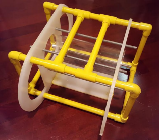
1Building the Frame
- Create two polypropylene wings
- These wings are manufactured with 0.9525 centimeter thick polypropylene sheets cut into a rectangular shape with a semi-circle edges on one side and tear-shaped edges on the other.
- Two “D” shaped holes, one 12.7 centimeter hole in the center for the electronics tube, four 0.635 centimeter holes for the threaded rods securing the electronics tube, and four 1.27 centimeter (½”) holes for the PVC tubing are cut in each tube. The tubing is fed through the 1.27 cm holes, extending 7 cm from the wings on both sides. The pipes perpendicular to each other are all connected by PVC connectors, and are sealed with PVC cement to ensure a rigid bond on all the connections.
- The tubing is fed through the 1.27 cm holes, extending 7 cm from the wings on both sides.
- The pipes perpendicular to each other are all connected by PVC connectors, and are sealed with PVC cement to ensure a rigid bond on all the connections.
- Frame is finished!
![]()
- Create two polypropylene wings
-
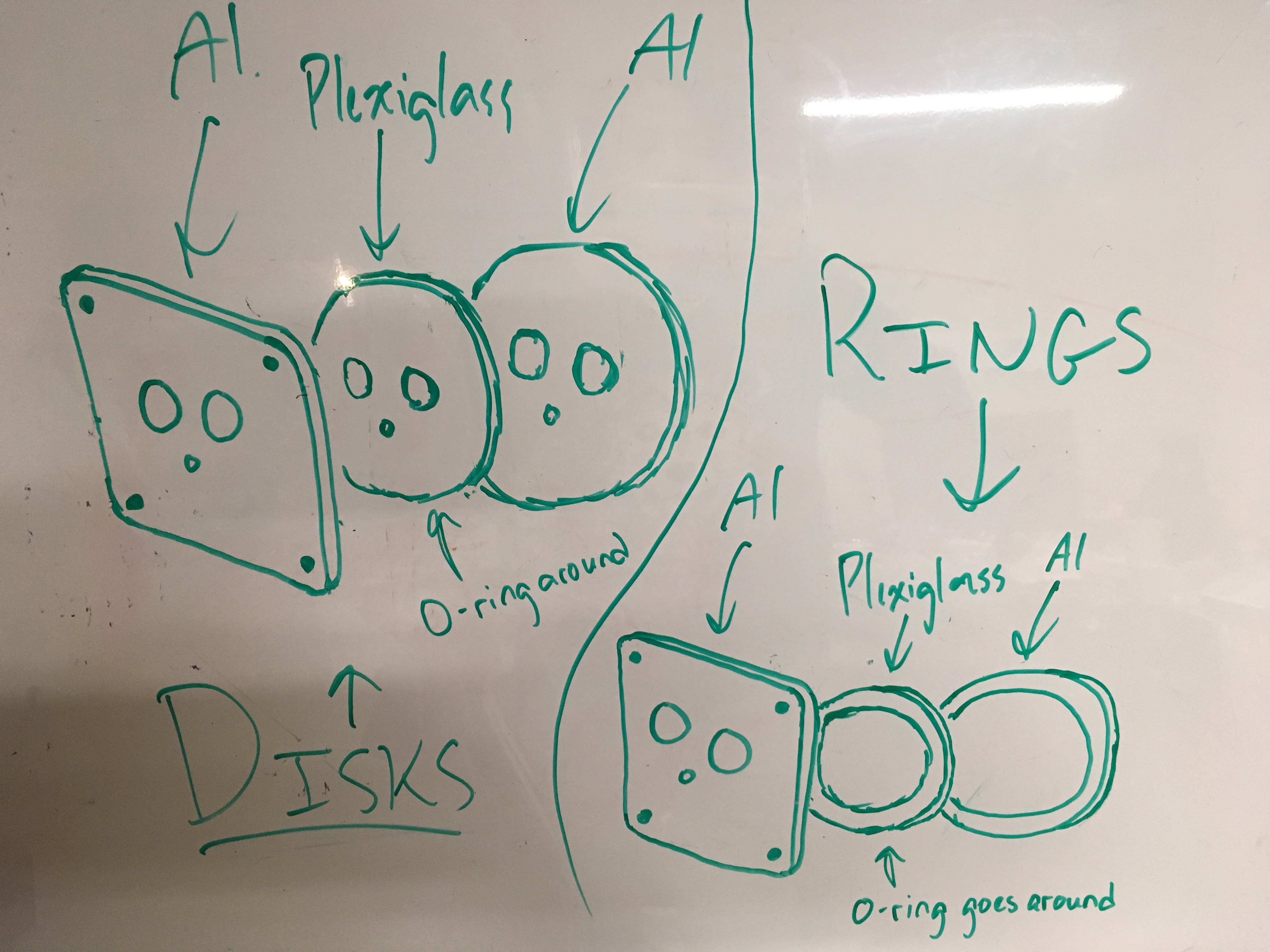
2Manufacturing the Aluminum End Cap
![]()
- Using this design, use a CNC milling machine to manufacture the aluminum endcap. Attached are the Inventor files for the actual measurements of the aluminum end cap.
-
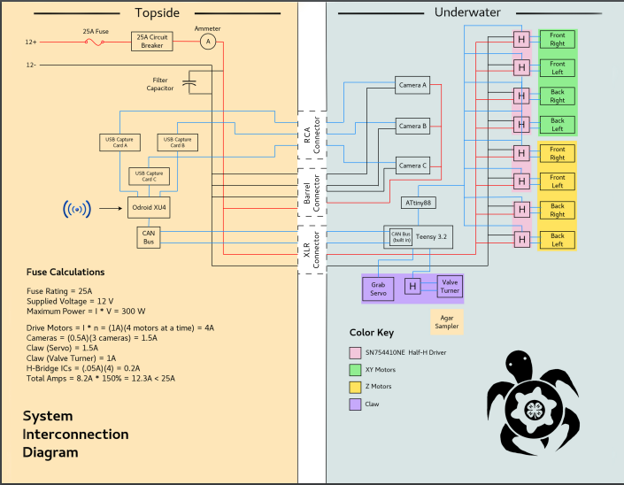
3Developing Surface Control Box and Electronics
- Find a 13.5” x 13” x 3.5” box made of durable yet flexible material (preferably plastic)
- Using the following SID (System Interconnected Diagram), lay out the surface electronics depending on the shape/size constraints of your surface control box (ONLY USE THE TOPSIDE ELECTRONICS PORTION OF THE SID)
![]()
3. Cut holes and mount a voltmeter & ammeter on the cover of the surface control box
4. Cut a hole on the left side of the box for an IEC C14 male connector. Use hot glue/wood glue or some other strong adhesive to seal the connector in.
5. Cut 2 holes on the other side of the surface control box (right side) for XLR connector sockets, and similarly seal with your choice of adhesive. Cut another hole next to those about 0.75 in. in diameter - this is for the barrel connectors to power the underwater cameras on the ROV. Next to that, cut 3 holes about 0.5 in. in diameter for the RCA connectors for underwater camera feed. Finally, dremel a hole about 1 ⅜ in. in diameter to the very right, lining it with a PVC ring sealed to the box with hot glue. This allows for easy access for programming the Arduino Uno.
6. Solder connections accordingly, and use appropriate screw sizes and lengths, velcro, zip ties, etc. to secure all your electrical components to the box.
And you should have yourself a nice surface control electronics box!
-
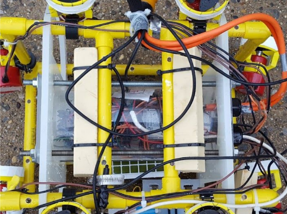
4Building Bottomside Electronics
Capabilities of bottom side electronics
- Control speed and direction of motors
- Open and close the claw
- Turn the claw
![]()
- Archelon’s bottomside electronics are housed in a 12.7 cm diameter acrylic tube sealed with custom-CNC-machined aluminum endcap plates.
- The aluminum end cap plates consist of a multiple layers of aluminum and rubber, compressed and secured tightly by 8 screws evenly spaced apart.
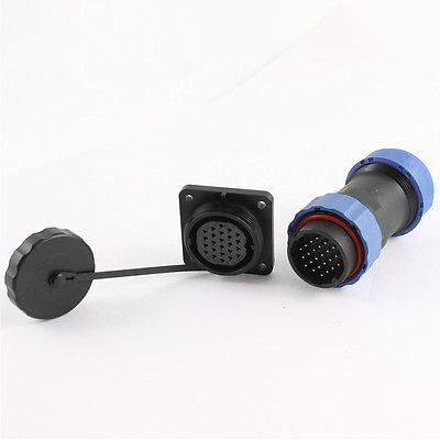
- The endcap plates have IP68-rated, military-grade waterproof connector penetrations, which allow for power supply as well as communication between the Odroid XU4 SBC and the Teensy USB-microcontroller board through the CAN Bus communication protocol.
- The bottom side electronics tube is comprised of two distinct control boards, separated into the motor driver and sensor control boards. All integrated circuits (ICs) and microcontrollers have corresponding IC sockets soldered into the boards, so that the electronics are easily replaceable.
- Use the given circuit schematic to wire the boards to the pcb. Place the circuit into the acrylic tube and close the end cap and the waterproof connectors.
-
5Propulsion System: Motors
- The motors of the Archelon ROV are developed through the modification of 8 Rule 800 GPH
bilge pump motors. Install three-blade 60 mm diameter plastic model boat propellers with bilge pump shaft adapters onto the bilge pump motors. The adapter also contains a screw that runs through the center of the propeller, so this must be secured with a washer and nut. - Mount the motors to the ROV using 3D printed housing and attachment pieces that were designed in Autodesk Inventor (see this project's attached files for Inventor files)
![]()
- The motors of the Archelon ROV are developed through the modification of 8 Rule 800 GPH
-
6Tether: Connecting Topside and Bottomside
1. Solder one XLR connector to three wires in the VideoRay neutrally buoyant tether (you can buy the 100 ft. version and then cut off 50 ft.) Repeat for another XLR connector. This is to provide +12V, GND, and communication between Arduino Uno on the surface to bottomside Teensy 3.2 module. Make sure to have a multimeter on hand so you can perform a connectivity test to keep track of the wires through the tether.
2. Solder the same wires in the VideoRay tether, but at the other end, to the waterproof connector with 7 holes. After doing so, apply heat shrink tubing to all the connections to ensure there are no shorts.
![]()
3. Weatherproof cable for data and power
4. Bundle tether with underwater camera cables so it becomes one giant manageable cable. Cables can be twisted so there’s no magnetic interference
5. Tether is permanently secured to bottomside tube using epoxy resin to seal
-
7Ballast System: Neutral Buoyancy
Neutral buoyancy on an ROV is desirable for optimal functionality and easy of use for the pilot/operator. Neutral buoyancy on the ROV is achieved through a combination of different ballasts and counterweights.
The largest ballast is the electronics tube itself; the acrylic tube is sealed with rubber O-rings and aluminum end caps, allowing it to function as a large, airtight ballast.
- Mount blocks of closed cell foam to the top of the ROV in order to make the top more buoyant than the bottom.
By carefully positioning these ballast components, the ROV has an overall neutral buoyancy. The ballasts are positioned away from the center of the ROV in order to allow the buoyant forces to exert greater torque, allowing the ROV to right itself more quickly in the event of being tipped over.
![]()
-
8Putting it all together
- Get a 12V DC Power Supply, and get/modify a cable with two banana plugs on the end (+12V and GND), an in-line fuse, and an IEC C13 connector at the other end.
- Start the scripts on the co-pilot and pilot interfaces.
Archelon ROV
The Archelon ROV is a low-cost, environmentally friendly Remotely Operated Vehicle (ROV) that helps to alleviate marine contamination.

Discussions
Become a Hackaday.io Member
Create an account to leave a comment. Already have an account? Log In.