-
1How to use Cura for slicing
I've created a plugin for Cura version 2.6.2 and 2.7-BETA. To use it download ToolChangePlugin.tar.gz, unpack it in the appropriate folder (eg. $HOME/.local/share/cura/2.6).
An example definition for a printer with 3 hotends is provided with the plugin. If want to use a different number of hotends open the file definitions/toolchanger.def.json with you preferred editor, change the machine_extruder_trains section.
"machine_extruder_trains":  {
    "0": "toolchanger_0",
    "1": "toolchanger_1",
    "2": "toolchanger_2" },
Copy/delete extruders/toolchanger_0.def.json as needed and change extruder_nr::maximum_value in each file accordingly.
"extruder_nr": {
    "default_value": 0,
    "maximum_value": "2"
},
In any case the following values should be changed for every extruder definition (eg. extruders/toolchanger_0.def.json). Cura needs to know the start and end coordinates for every tool to avoid traveling across the printed object.
"machine_extruder_start_pos_abs": { "default_value": true },
// tool X - lock
"machine_extruder_start_pos_x": { "default_value": 146 },
// tool Y - clearance
"machine_extruder_start_pos_y": { "default_value": 255 },
"machine_extruder_end_pos_abs": { "default_value": true },
// tool X + lock
"machine_extruder_end_pos_x": { "default_value": 160 },
// tool Y - clearance
"machine_extruder_end_pos_y": { "default_value": 255 }
(Re)start Cura and add a new printer. You will find the example in the section Local of the "Add Printer" dialog. You should now have a new printer with, among others, Configure Tool Changing and Machine Settings buttons in the Manage Printer dialog.
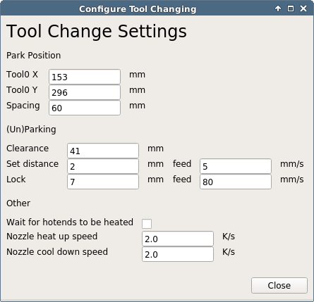
The plugin assumes that your tools a located equidistant from left to right along the X axis of your printer. Tool0 X/Tool0 Y are the coordinates at which the XY carriage just mates with this hotend in the park position. Spacing is the distance in X between two hotends. Clearance is the amount of travel that must be mad straight in Y to avoid running into other hotends, or in other words, the depths of your print area should not be more than Tool0 Y - Clearance. Set distance is an additional travel in Y made while loading a new tool, to ensure it is proper loaded (the tool rest is somewhat flexible in Y for exactly this reason). Lock finally is the travel in X to unlock/lock a tool to the rest.
![]()
The given example will create the following Gcode:
; load tool 0
G0 X153 Y255 F7200  ; move to the edge of print area, center to the tool
G0 Y296 F4800       ; pickup the tool
G0 Y298 F300        ; ensure proper fit
G0 Y296 F4800       ; move back to reduce friction while unlock
G0 X146 Z0          ; unlock
G0 Y255 F7200       ; move straight back to the edge of the print area
;unload tool 0
G0 X160 Y255 F7200  ; move to the edge of print area
G0 Y296             ; move straight to the rest
G0 X153 F4800       ; lock the tool to the rest
G0 Y255             ; back out carriage from the tool
; load tool 1
G0 X213 Y255 F7200  ; X coordinate is the only difference
G0 Y296 F4800
G0 Y298 F300
G0 Y296 F4800
G0 X206 Z0.3
G0 Y255 F7200
The last step is setting the correct Nozzle offsets per extruder in Machine Settings. X and Y offsets are handled by Cura, but Z offset must be managed by the printer firmware. Dealing with offsets in two different places sounds complicated, but is actually a feature. If X and Y would be managed by the firmware, the code to load/unload would need to account for the offset, but having Z offset known by the firmware makes it easy to calibrate the bed with every tool head.
Nozzle offset calibration is beyond the scope. I've written about the way I'm doing it, but my tooling isn't yet good enough to be released. My plan is to add camera support for offset calibration to the plugin.
-
2Assembling a hotend
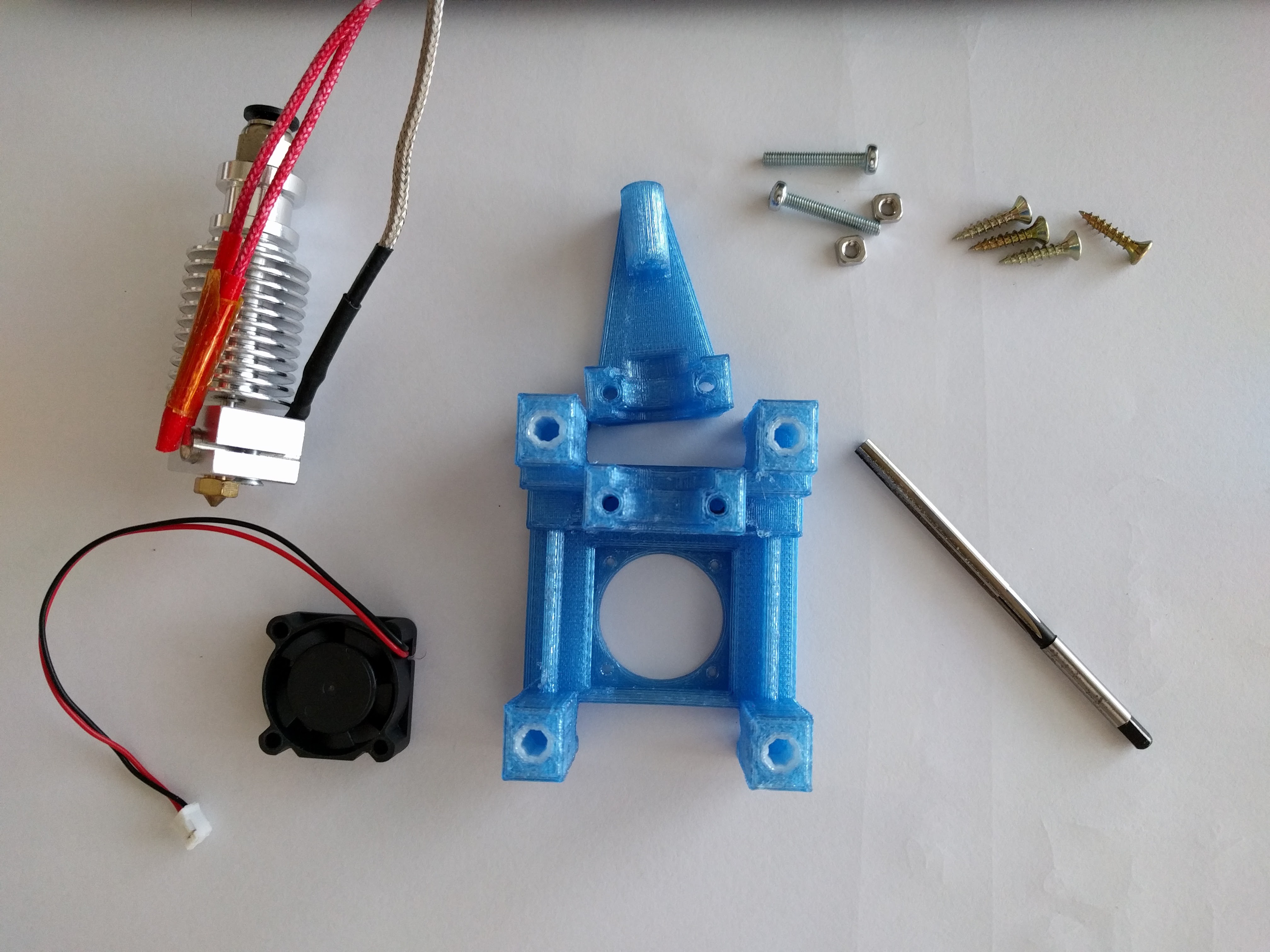
Required parts
- Prrint hotend-v2-single.stl or hotend-v2-dual-PETG.stl and hotend-v2-dual-POM.stl. I used 3 shells, 0.2 mm layer height, 4 top/bottom layers and 30% infill for PET-G part and one shell, 0% infill 0 top/bottom for POM.
- 2 M3x20mm round head screws
- 2 M3 square nuts (hex works as well)
- 4 3x15mm wooden screws
- J Head long range hotend
- 25x25x10mm fan
Special tool
- 4mm-H7 reamer
Clean the printed parts as needed, use drill bits to clean the screw and bowden tube holes. I used a 4mm-H7 reamer to widen the holes of the bushings to the correct diameter (I'm using 4mm-h6 pins). A 4mm drill bit might work as well.
![]()
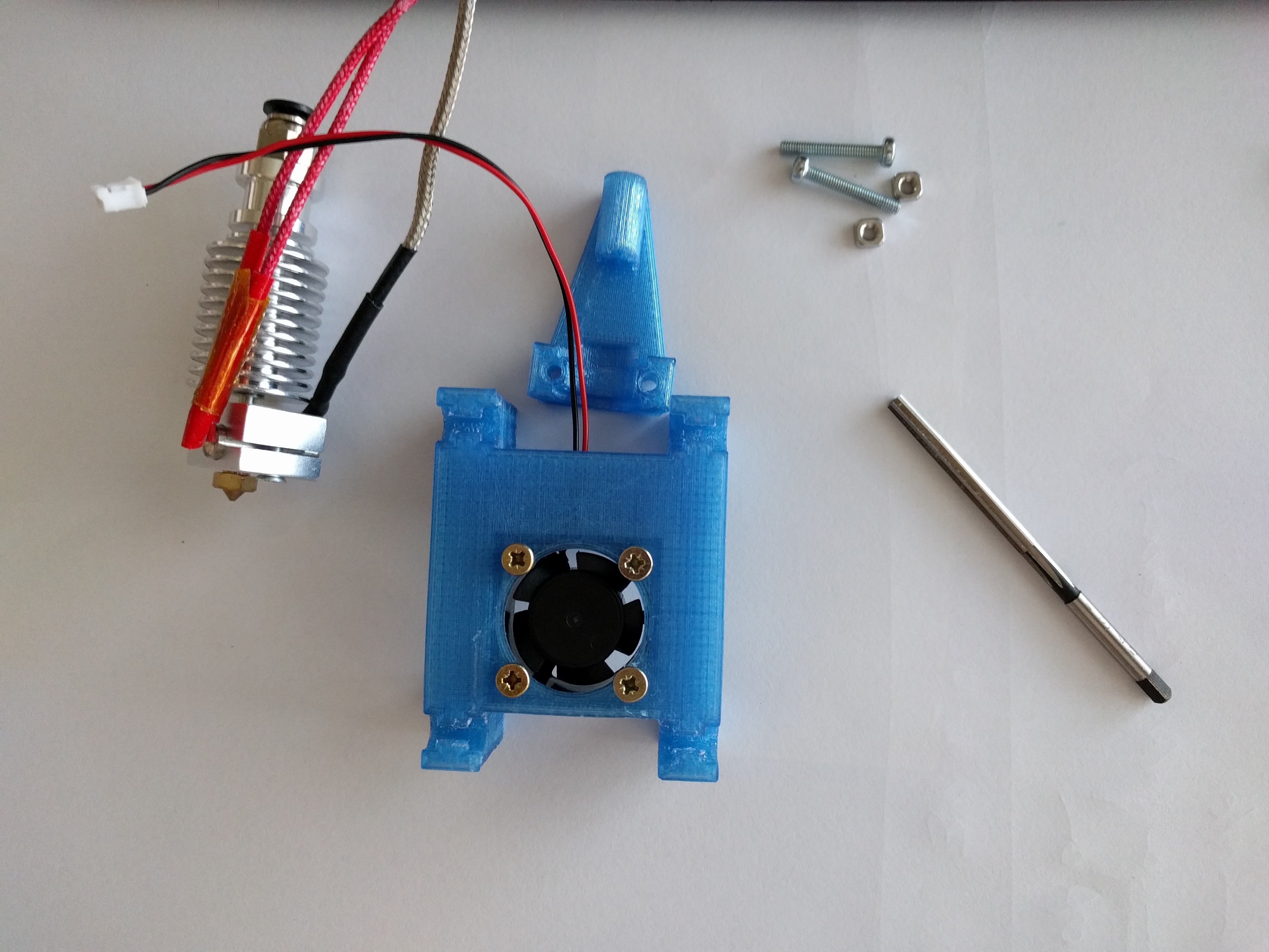
Screw in the fan from the back
![]()
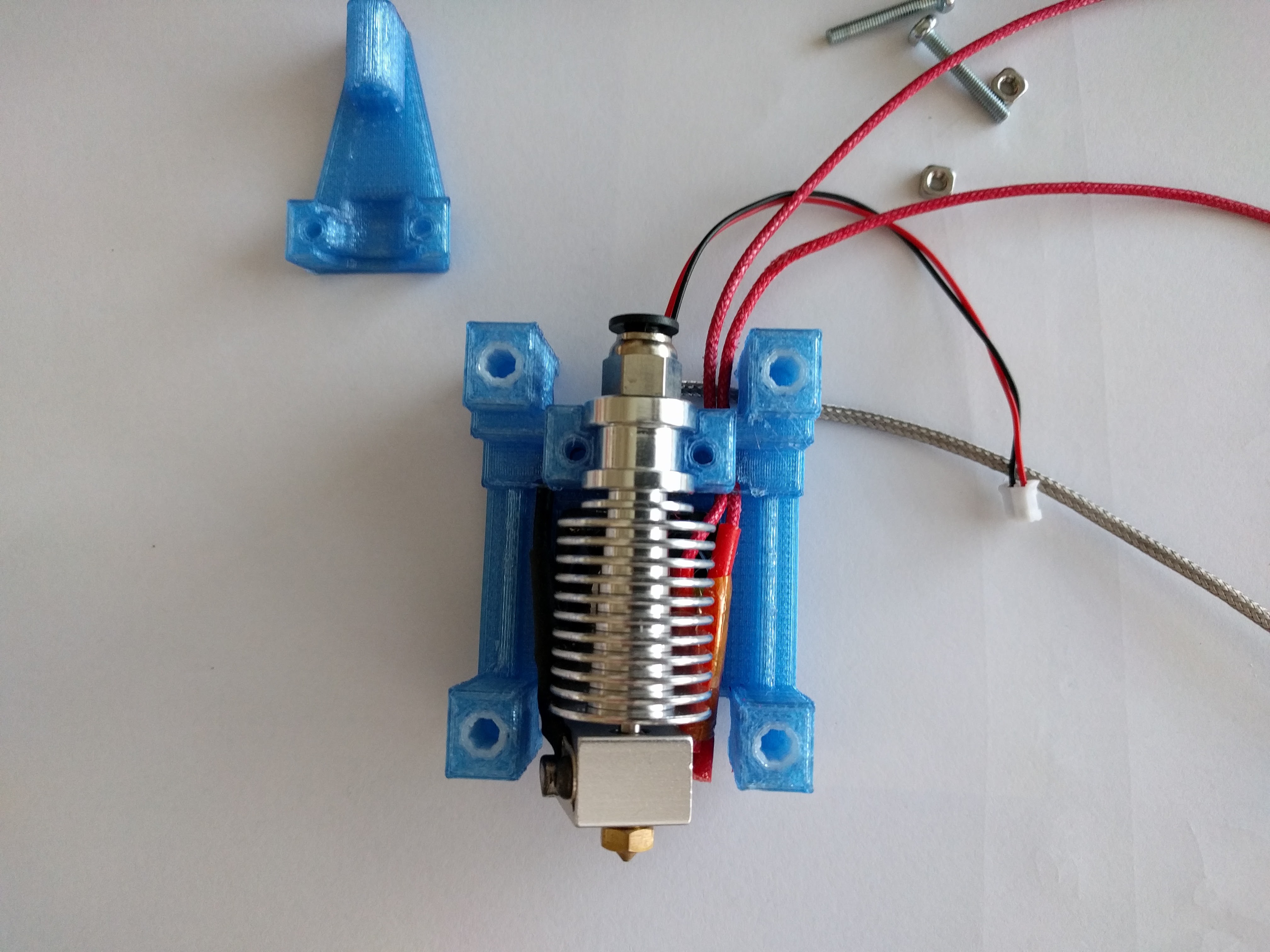
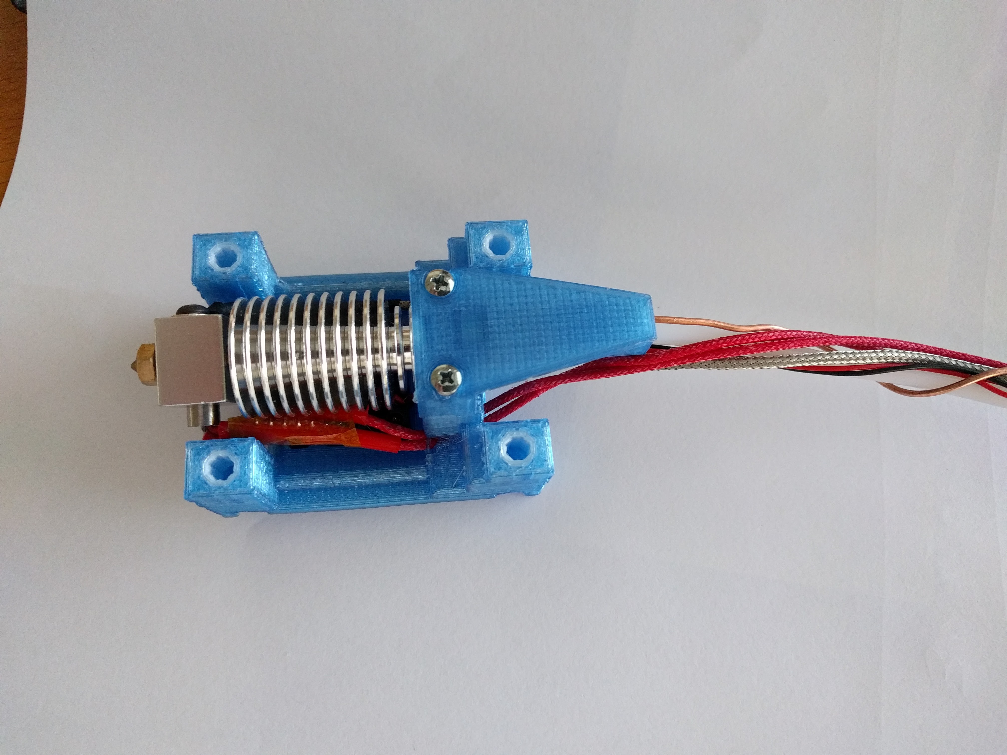
Insert the hotend. Run the heater and sensor cables on opposite sides. Twisting the heater block slightly makes it easier to access the sensor screw once the hotend is fully mounted.
![]()
The hotend usually fits very tightly and the gap between the two printed parts is to big for the screws to grab. Use a vice to gently squeeze them together the first time and tighten the screws. Longer bowden tubes are sometimes a bit wobbly, warping around 1.5mm² cooper wire helps with this issue.
![]()
-
3Molding a nozzle plug/wiper
The nozzle plug/wiper is made from a high temperature (350°C/650F) sealant/gasket silicone used eg. in the automotive industry (eg. K2 Black High Temp Silicone, sells for $6 on Amazon). Neither of PLA, PET-G or POM seems to stick to it, and I assume that this is true as well for almost any other plastic used in 3D printing.
![]()
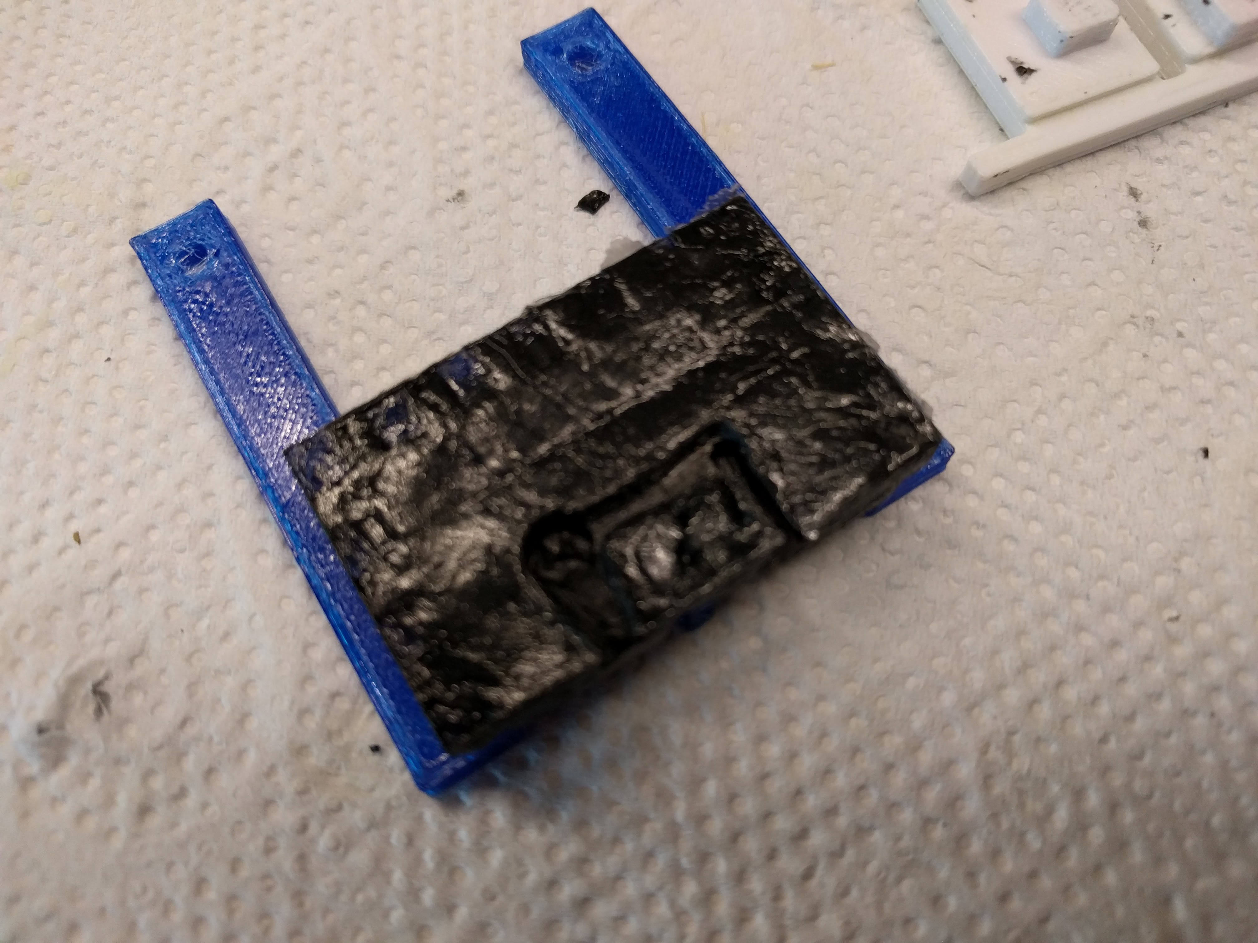
The process is very straight forward. Print wiper-v2.stl (blue parts) and wiper-mold.stl (white parts, printed with 0.1mm layers). Soak both mold parts in a mixture of water and dish soap and assemble all as show below. The dish soap prevents the silicone from sticking to the mold (release agent ) while the water provides the humidity to cure the silicone. Keep the wiper part as dry as possible.
Squeeze a big blob of silicone in the center, preferably in one go to avoid trapped air bubbles and use a spatula to spread it out towards the features and edges of the mold. Let it sit for at least 18 hours to cure.
Tool Switching - Multi Extrusion
A scaleable approach to multi extrusion, easy to adopt in most CoreXY/H-Bot printer designs.
 rolmie
Discussions
Become a Hackaday.io Member
Create an account to leave a comment. Already have an account? Log In.