rolmie
-
About repeatablity of tool switches
10/20/2017 at 21:03 • 1 commentThe calibration tool is feature complete, but requires one more round of code refactoring.
I recently added a feature to test the whole design for repeatablity. The basic idea is to to take a reference picture of each nozzle and compare it to a picture take after unload and load.
OpenCV provides a function called phaseCorrelate which estimates the shift between to pictures in (sub)pixel. The process is calibrated by moving the hotend a known distance in the beginning. The camera I'm using has about 4.2µm/pixel resolution.
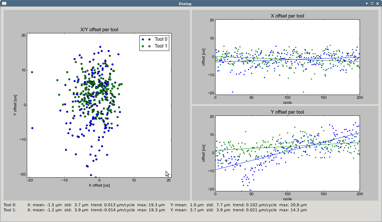
Below are the results of 200 load/unload cycles with two tools in the sequence T0 -> T1 -> T0 -> T1 -> ... . The plot on the left shows all nozzle positions, while the right part is X and Y separated over time.
![]()
In short, the repeatability is in the ballpark of 20µm over 200 load/unload cycles which is identical to a 200 or 400 layer print (depending on the slicer). The Y axis seems to have a steady trend. The reason is yet unclear to me. It can't be step loss, because this would affect both tools. Thermal drift (the test lasts about 40 Minutes) maybe? Overall I'm not concerned about it, it is good enough for the purpose.
-
Update: Cameras and Calibration Tool
09/24/2017 at 20:30 • 0 commentsOnly a brief update, as it is late already, but I'm eager to get a few news out.
I just uploaded CAD and STL (case, diffuser) files for the inspection camera. The cover is a dual extrusion print with transparent PLA used as light diffuser. I'll add detailed instructions in the next days.
![]()
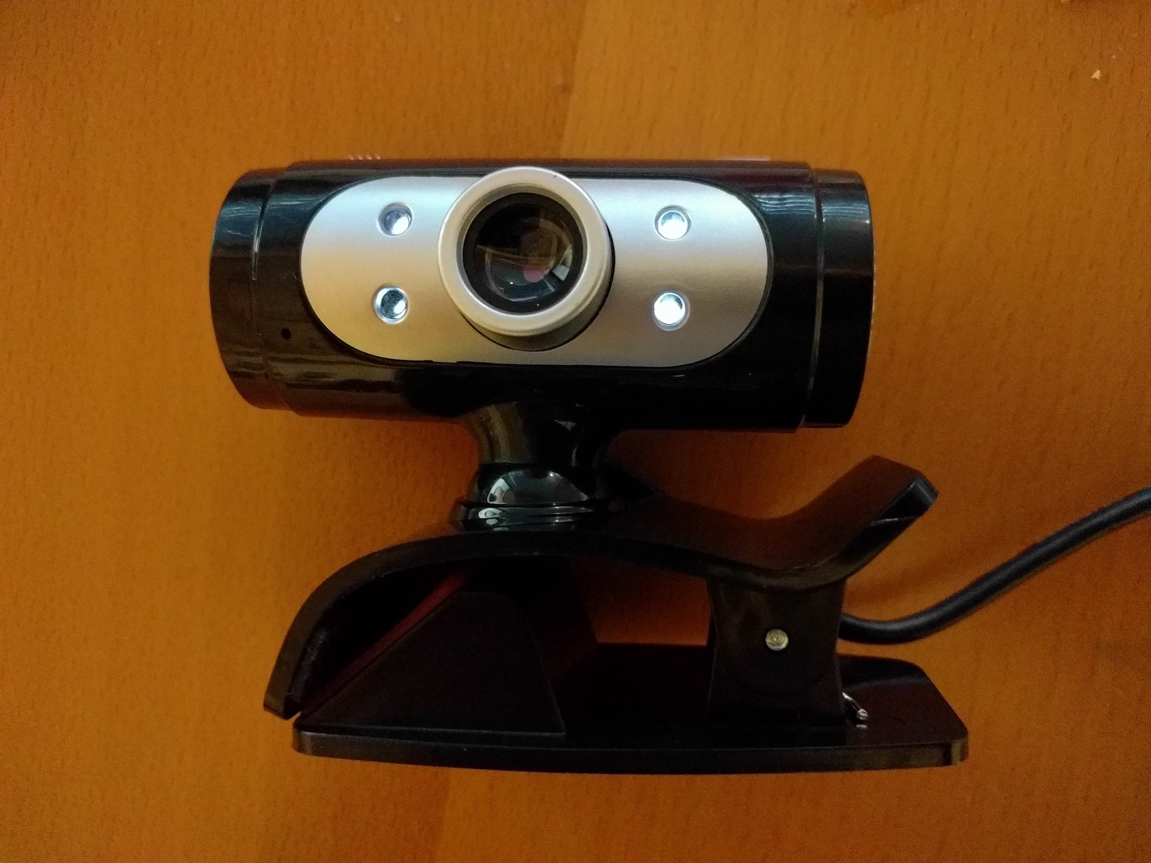
The case is compatible with these two cameras (amazingly PCB dimensions, mount hole distances etc are the same). The first one is available for about $12. It features an 720P chip with support for MJEPG compression, which allows for 30fps in all situations.
![]()
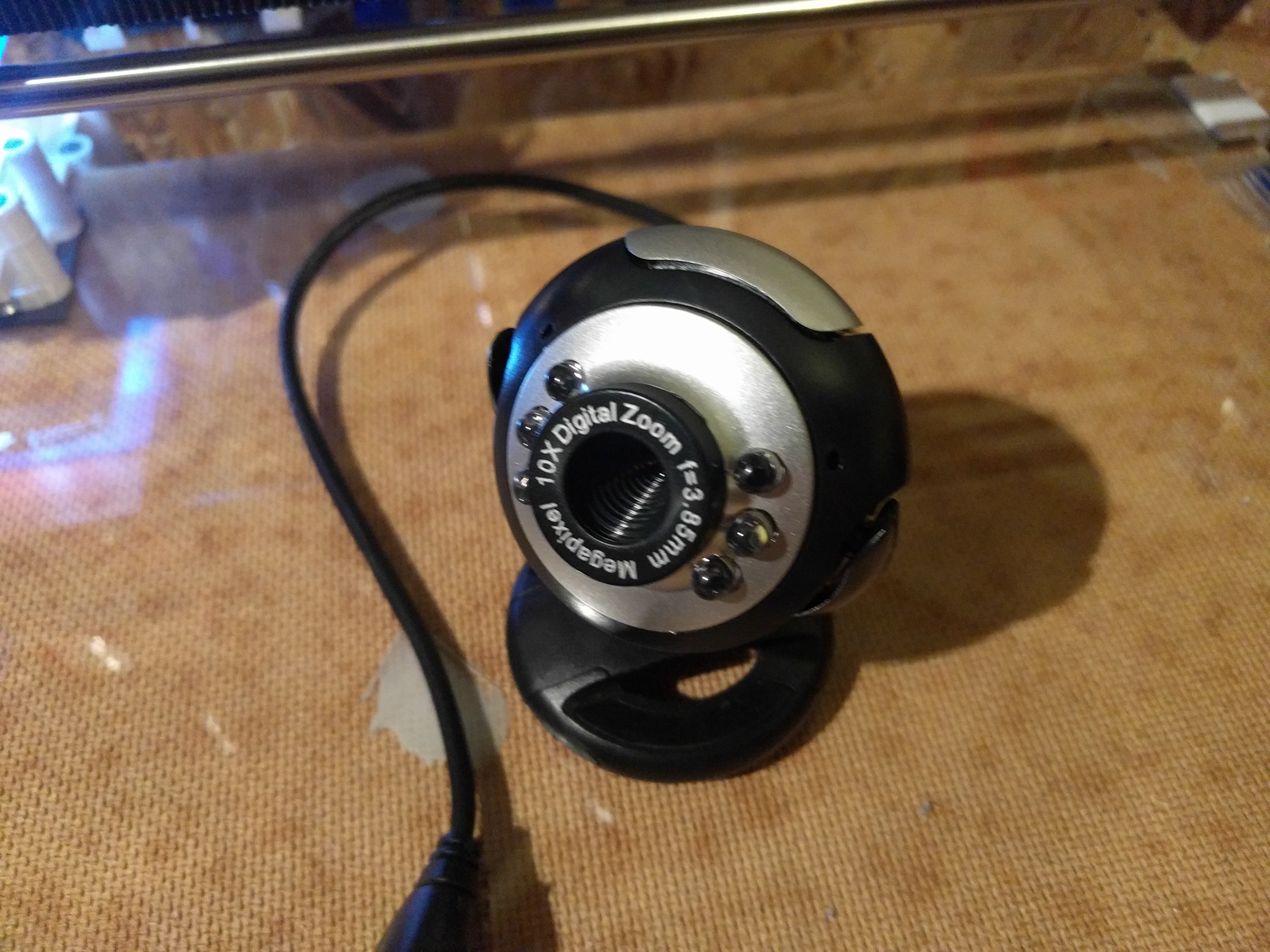
This one is available for about $6, but only supports 640x480. The frame rate sometimes drops down to about 5 fps and the overall image quality is blurry. It is good enough for the job, but not convenient to work with.
![]()
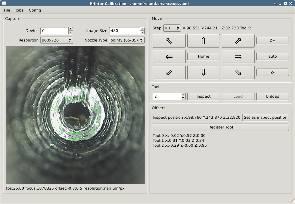
The calibration tool is also slowly progressing towards being feature complete. The UI is now much cleaner an easier to work with. It keeps a reference image of each nozzle after registration which is later used to estimate the offset after a reload and to estimate the resolution of the camera (µm/pixel).
![]()
A few TODO's are left, eg. nozzle types are still hard coded, significant offsets in are Z difficult to work with, offset measurements are given in pixel instead of µm ...
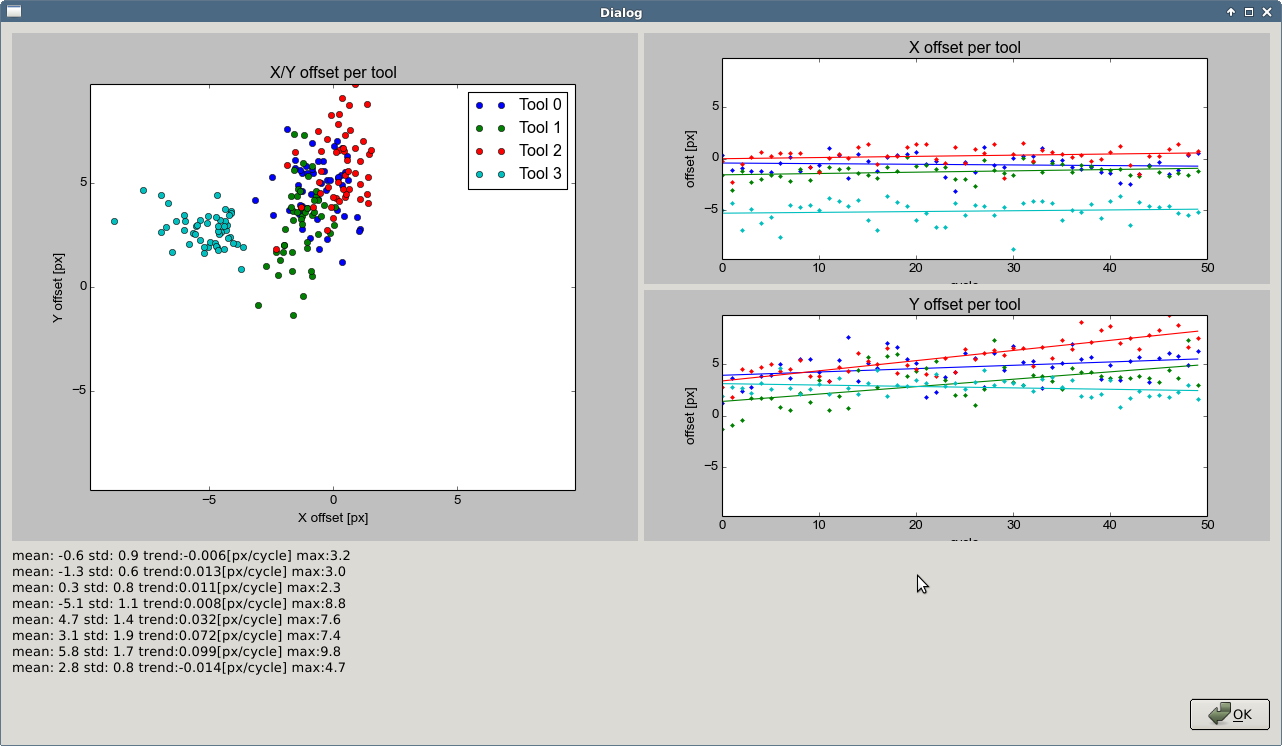
My favorite feature is the repeatability measurement job. All tools are loaded repeatedly and the reference image is used to estimate the XY offset. The plots below are in pixel, the camera resolution is about 4.5µm per pixel, each tool was loaded 50 times. "Tool 3" is a reference point on the carriage, unaffected by tool changes.
![]()
It is very useful while tuning, eg. I figured that my printer was loosing steps in Y because I pushed the carriage to hard. I'm a still a bit concerned about the trend in the Y offset of tool 0 and tool 2, investigation is ongoing.
-
WIP - Offset Calibration Tool
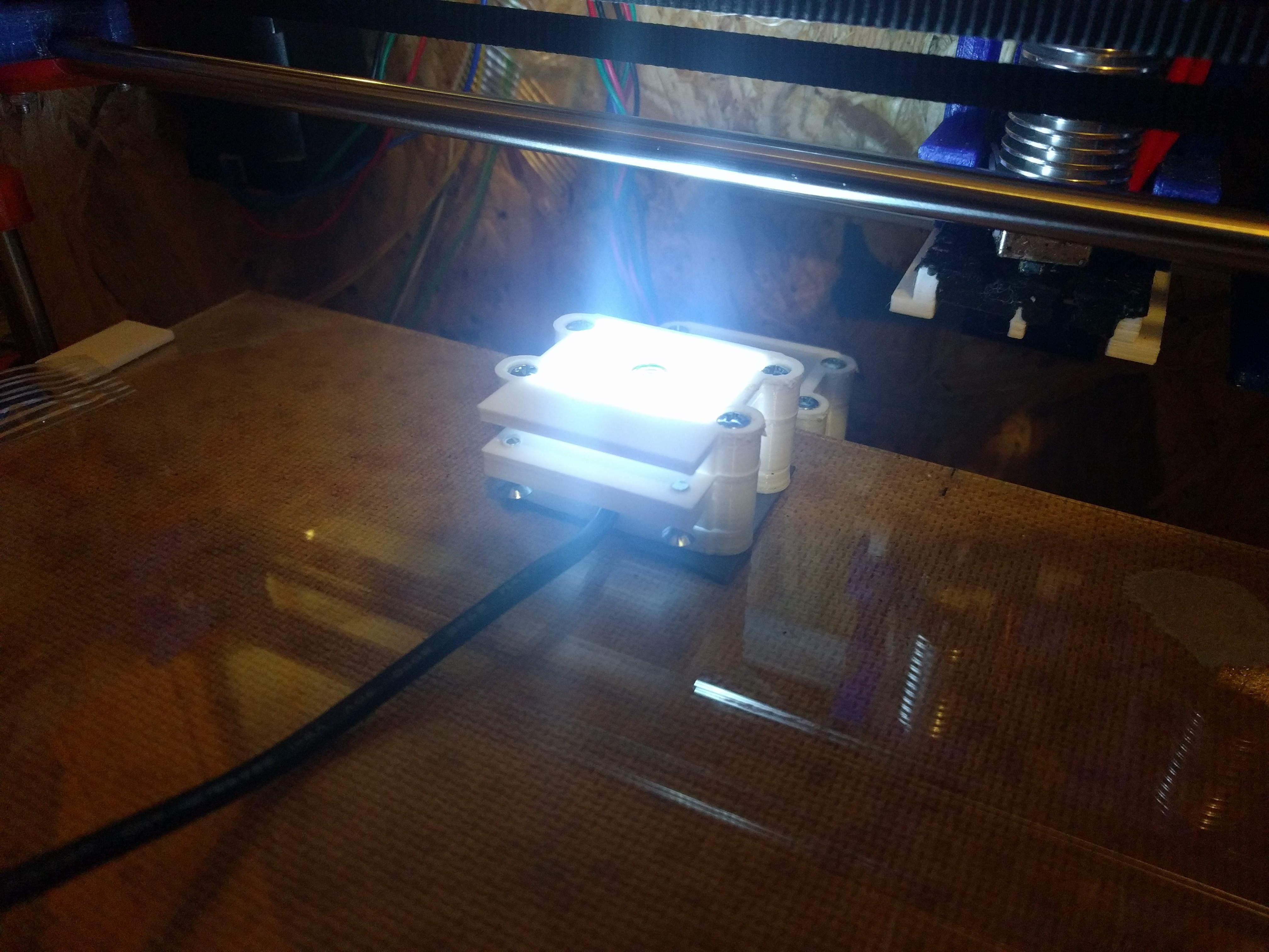
09/07/2017 at 12:52 • 1 commentThe new camera works great and is now permanently attached to my prototyping printer. The camera comes with 6 white LED's, which are still used, but now covered by a thin layer of transparent PLA to spread the light.
![]()
Better software for calibration is on the way, too. The GUI is pretty horrible mainly because I suck at UI/UX (any UI/UX people around to help out) and I have no experience with Qt.
Nevertheless, once configured, it is easy to work with. No more accidental crashes, no more attempts of unloading a tool in the wrong position. no more collisions with the camera. Some of the planed features are:
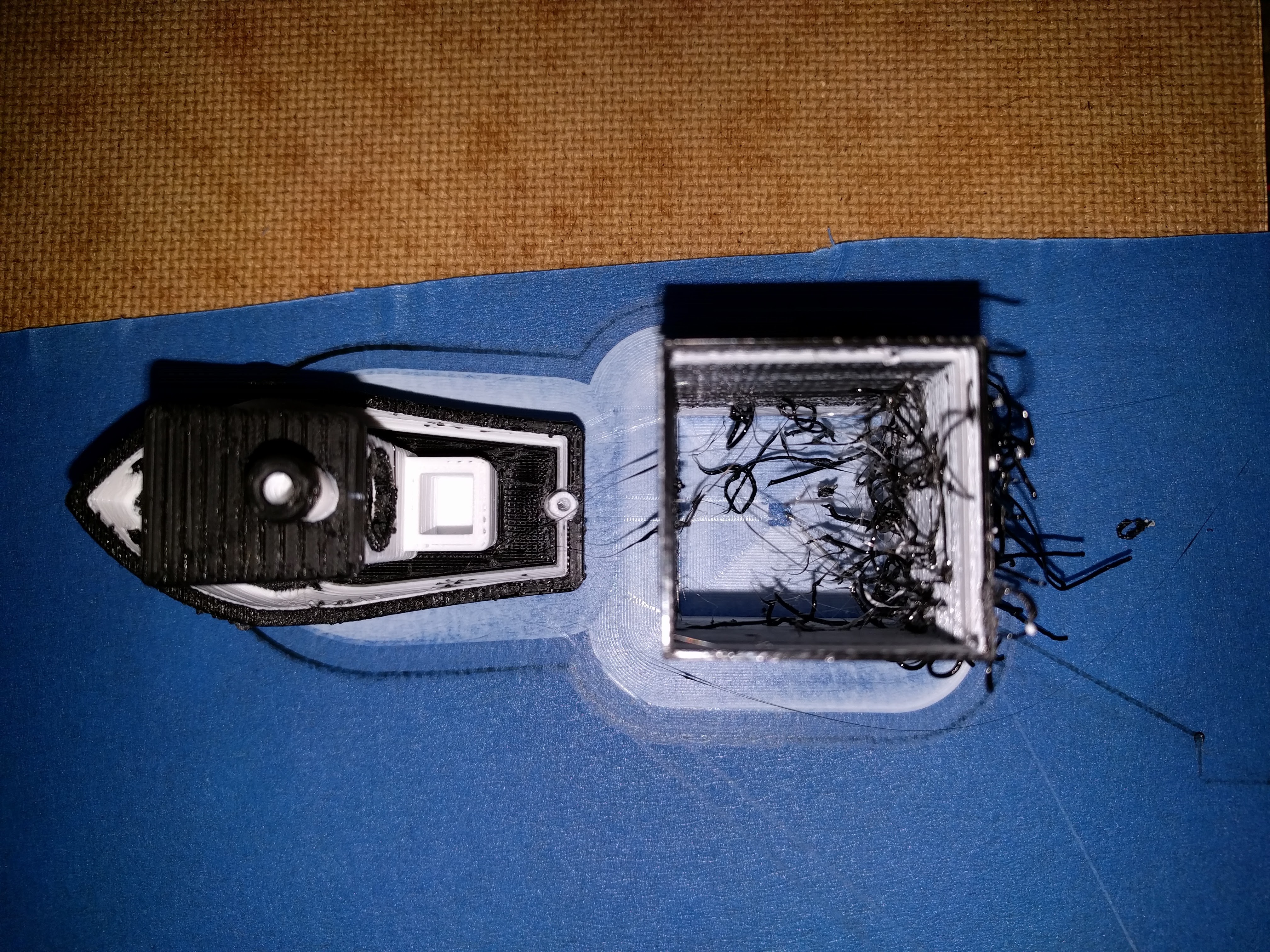
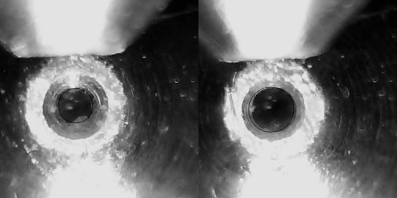
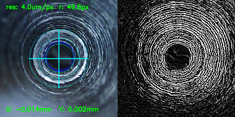
- XY Calibration: Circle detection works great on new and used nozzle after careful parameter tuning, but so far, the results are very unsatisfying for used nozzles, with eg. blobs of filament in the center. Manual calibration requires less than a minute per hotend.
- 'Auto Focus' Z calibration: I found a good paper about blur blur detection which boils down to compute the variance of the laplacian of an image. The tool restricts the computation to the area enclosed between the two circles. As of now, the result is only shown (bottom left), but it should be possible to automate in a very similar way to 'Auto Focus' in cameras.
- Testing Repeatability: A reference image of each nozzle is kept and used to estimate the X and Y offset after unloading and loading, by calculating the phase correlation of the laplacian of both, the reference and the current image. I have plans to run some endurance tests, to eg. see if the design is stable enough for 1000 load/unload operations per tool.
- At least support for Smoothieware and Repetier firmware, but I try to stick generic G-Codes as much as possible.
- Support for USB and network (untethered) connections to the printers, but no plans for WiFi cameras so far.
![]() Tool 0, used brass nozzle
Tool 0, used brass nozzle![]()
Tool 2, unused stainless steel noozle
In case you wonder, Laplacian is the second order derivative of a gray scale image. This is commonly used for eg. edge detection etc
![]()
-
WIP - Offset calibration camera
08/31/2017 at 18:24 • 0 commentsUPDATE 2017-09-07: The camera works great even without additional lens, just by shortening the lens holder by about 8mm. Otherwise to much light is blocked of the nozzle at the focal point. I ordered a few more budget USB cameras to see if this is reproducible with others. Stay tuned.
At the moment I'm using a USB microscope, temporarily fixed to the build plate for nozzle offset calibration (more details). It works, but what I really want is a camera permanently attached to the printer to make it easier to check and verify the current offsets and collect data about the long term stability and repeatability of the tool switching system.
The microscope is pretty difficult to integrate, so far I found now way without major downside. First issue is the form factor, it is cylinder about 120mm long and 12mm diameter. Attaching it upright to the build plate would significantly reduce the usable space in Z. Second, the short focal length makes it easy to run the nozzle into the microscope if used horizontally with a mirror (what I'm doing now), as the tip of the nozzle needs to moved below the top of the microscope case. Third the price, it is pretty expensive compared to a simple USB camera and maybe hard to procure as well.
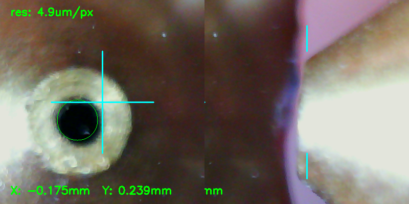
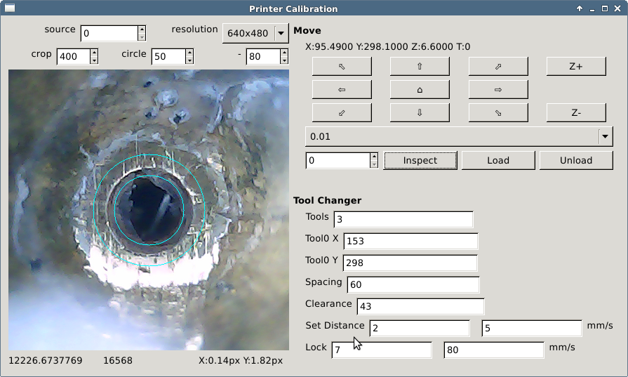
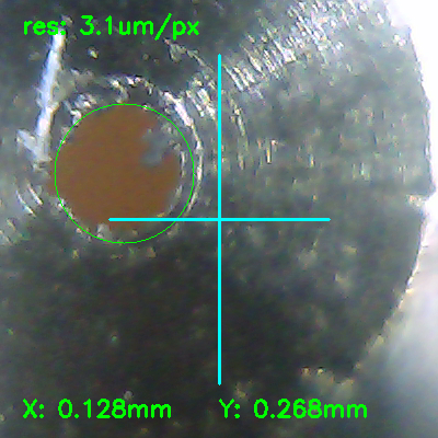
Thankfully, the internet is full of "USB camera to microscope conversion" guides. And what looks promising is using a simple webcam (640x480) and a lens with a short focal distance, harvested from a green laser pointer.
![]()
The estimated resolution of 3.1 µm/pixel is slightly better than what I got with the USB microscope (about 5µm/pixel). The estimation is based on the diameter of the circle (pixel) and that it is a 0.4mm nozzle.
![]()
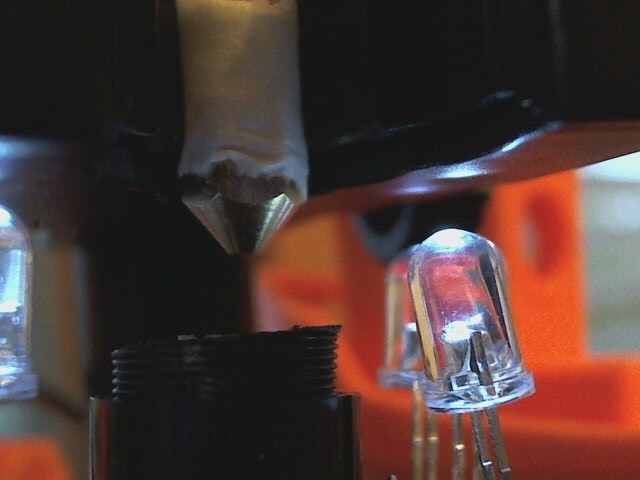
The focal distance is about 6-7 mm, enough to keep 2-3 mm safety distance between the camera and the nozzle.
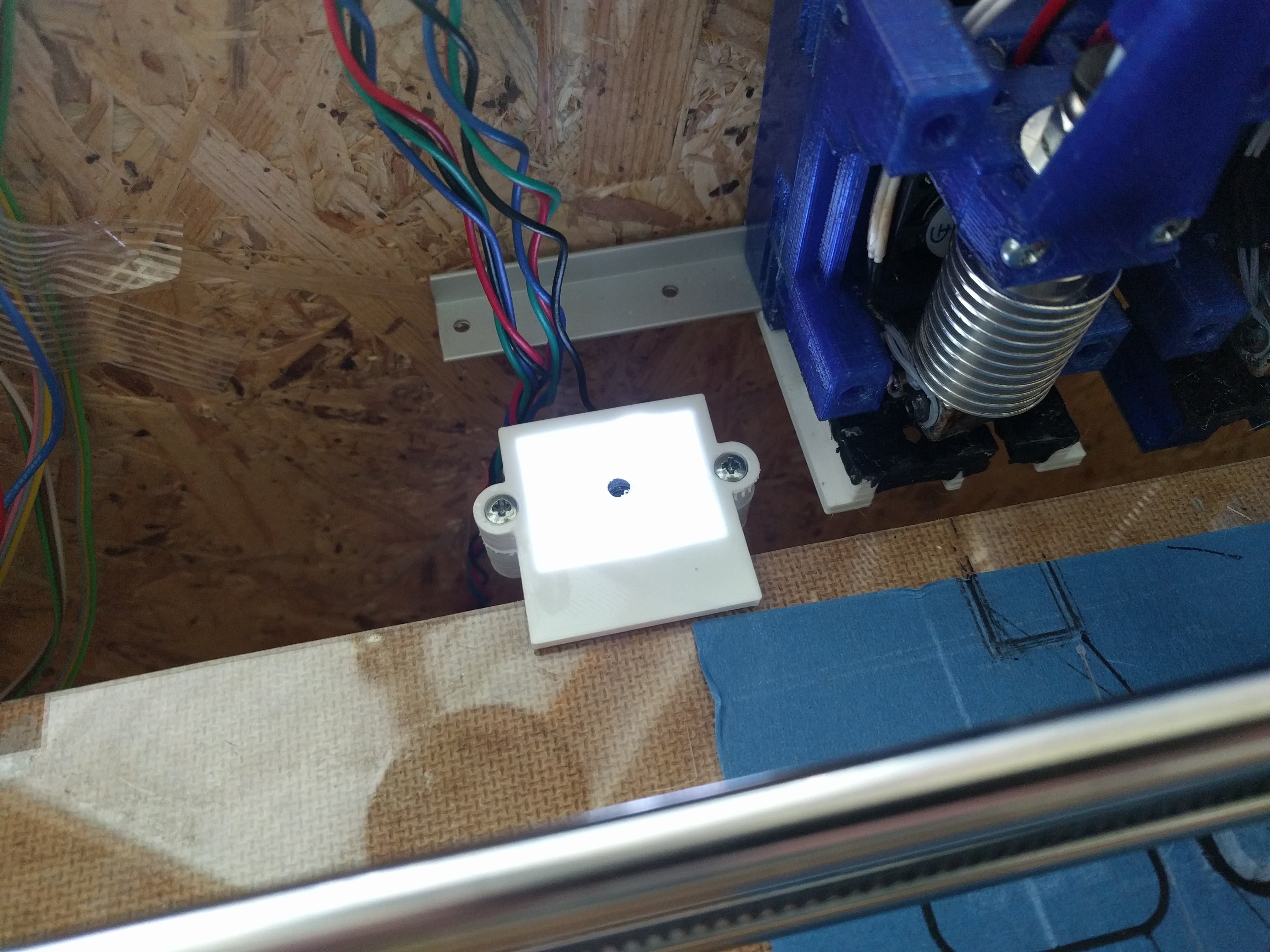
The plan is to keep the camera module in a upwards looking direction permanently attached to the build plate. X and Y offsets are still optically calibrated and Z could be done by eg. touching a micro switch with the nozzle once x and y offsets are known (to ensure the nozzle will hit the switch).
The only downside is the harvested lens, the specs are unknown to me. I ordered a set of smartphone camera lenses (zoom, fish eye, macro and wide field), maybe one of these is usable as well.
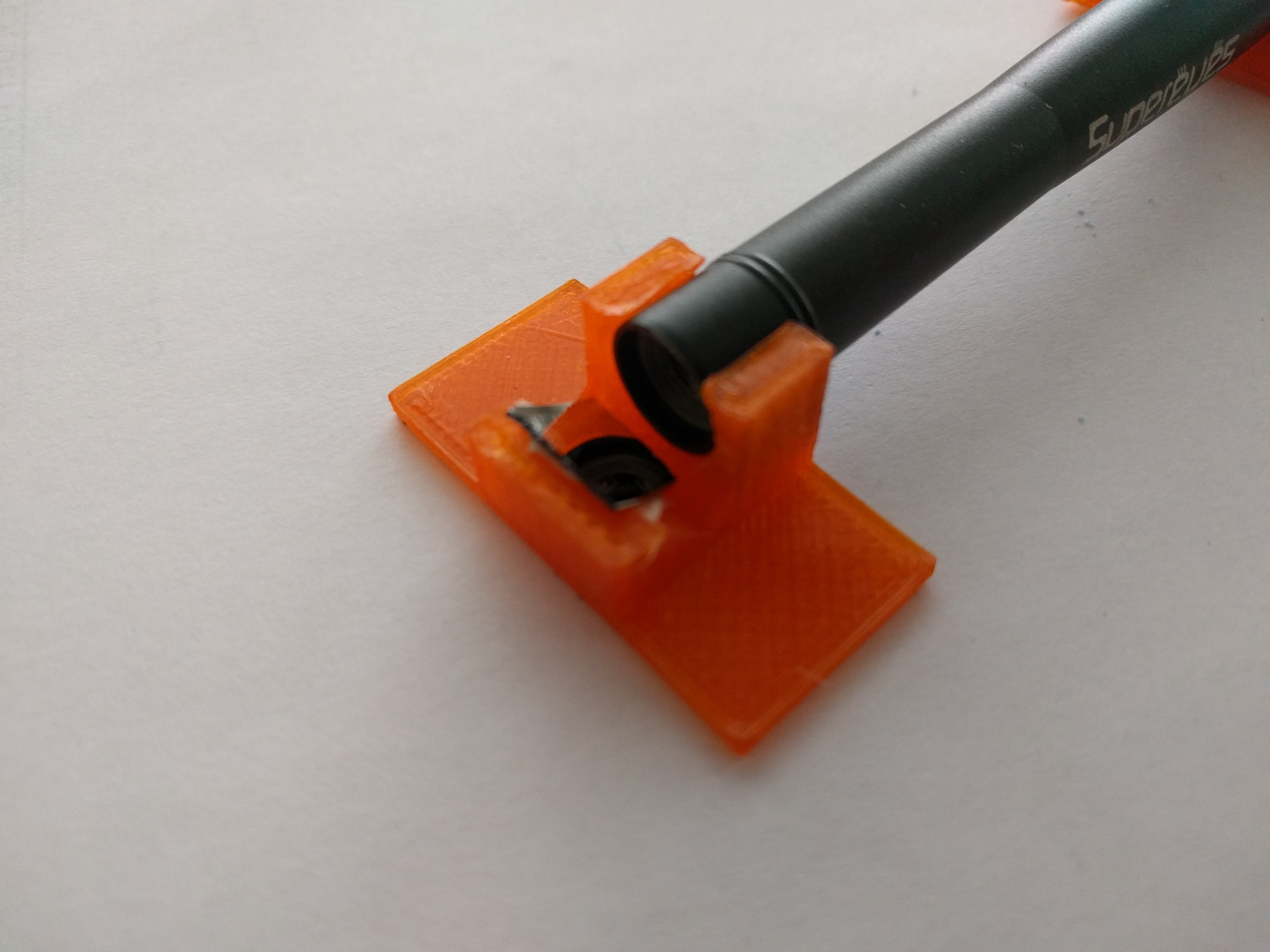
For reference, a picture of the camera.
![]()
-
At Work
08/24/2017 at 07:19 • 0 commentsStill using only two hotends, but that is only limited by the board I'm using.
-
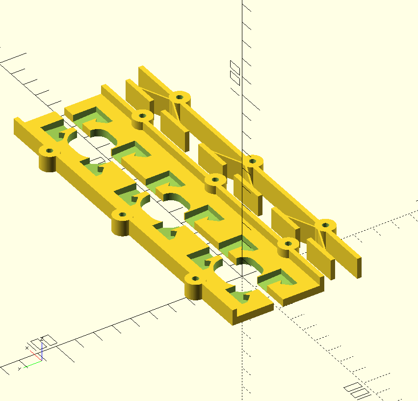
Redesign - First Print and Parts
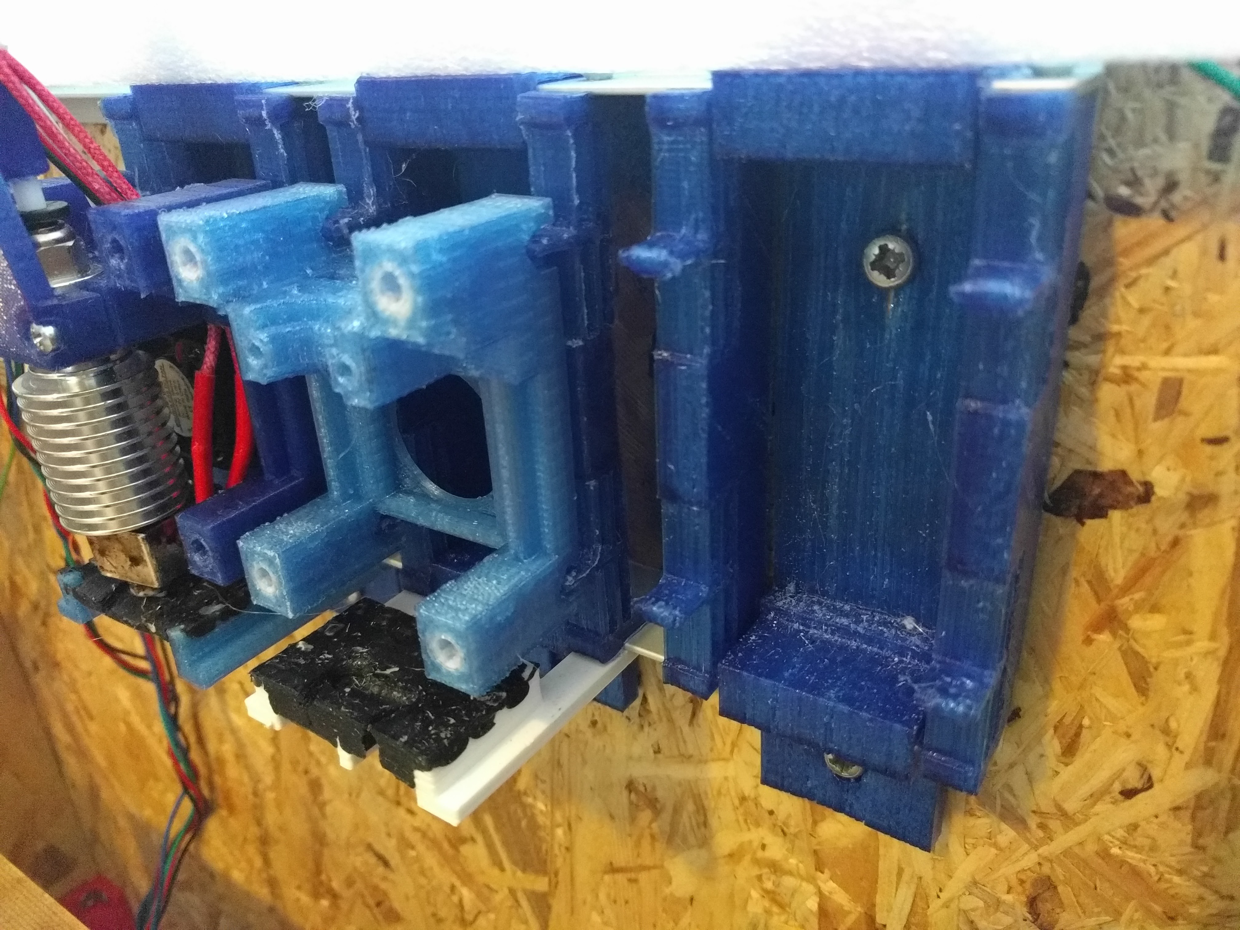
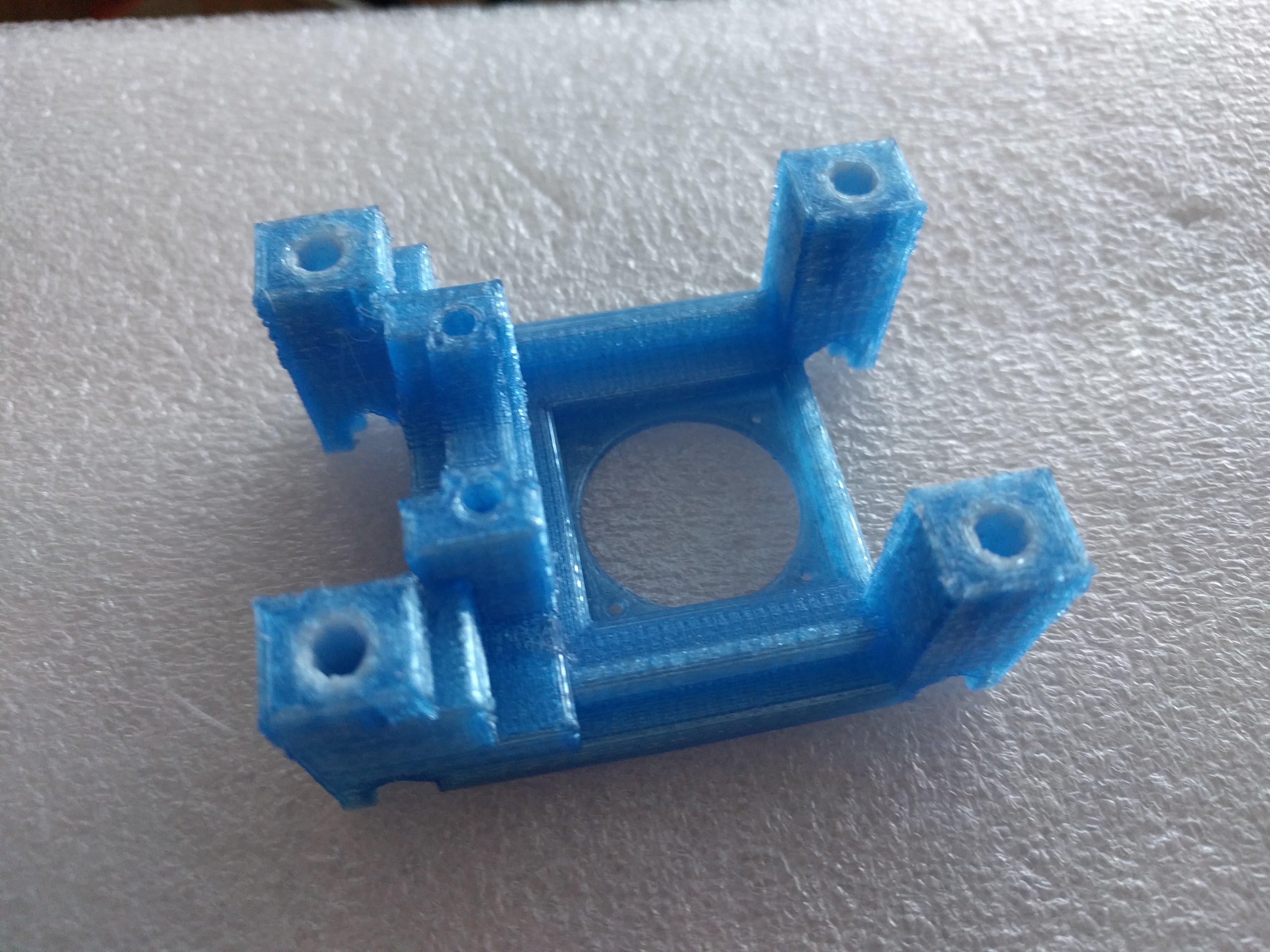
08/18/2017 at 16:56 • 0 commentsThe project entered a new stage, the prototype is good enough to bootstrap itself to print better parts. Below is an image of the hotend fixture that is printed in PET-G (light blue) and POM (white, low friction wear resistant) to replace the previously used brass bushings.
![]()
The joint between the carriage and the hotend is now made out of four printed 4mm bushings (instead of two brass) and four 4mm shafts. Loading and unloading is now faster and smoother. The overall design is very compact and forms an air duct to guide cooling air down to the printed part.
![]()
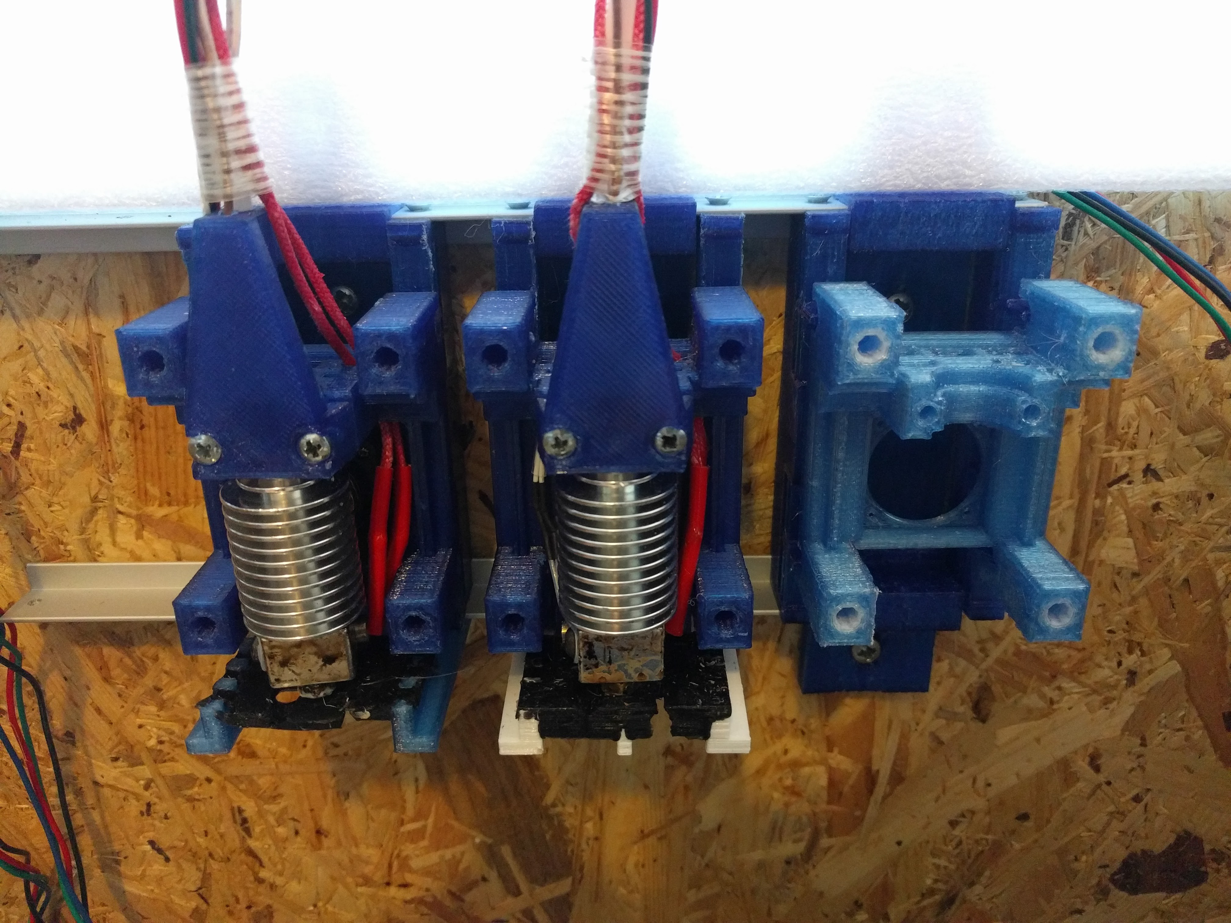
![]() carriage without hotend
carriage without hotend![]() carriage with hotend
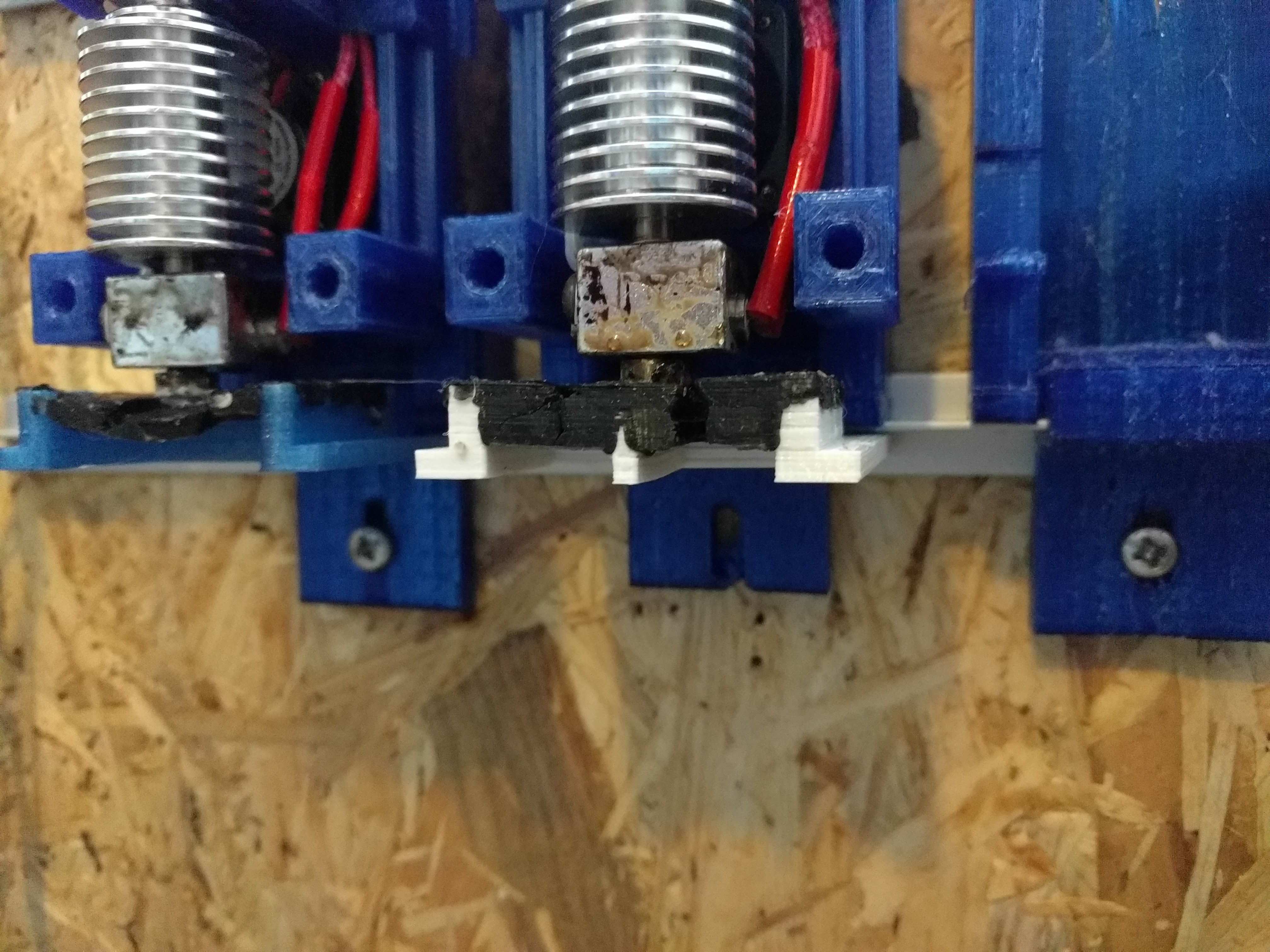
carriage with hotend Four pins and holes are now used to provide a enough support for unused hotends sitting in the rest. It is possible now to block the nozzles with a silicone wiper and prevent oozing. Additionally, the hotend is now moving in only one direction over the wiper, which reduces the chance of picking up previously removed filament.
![]()
![]()
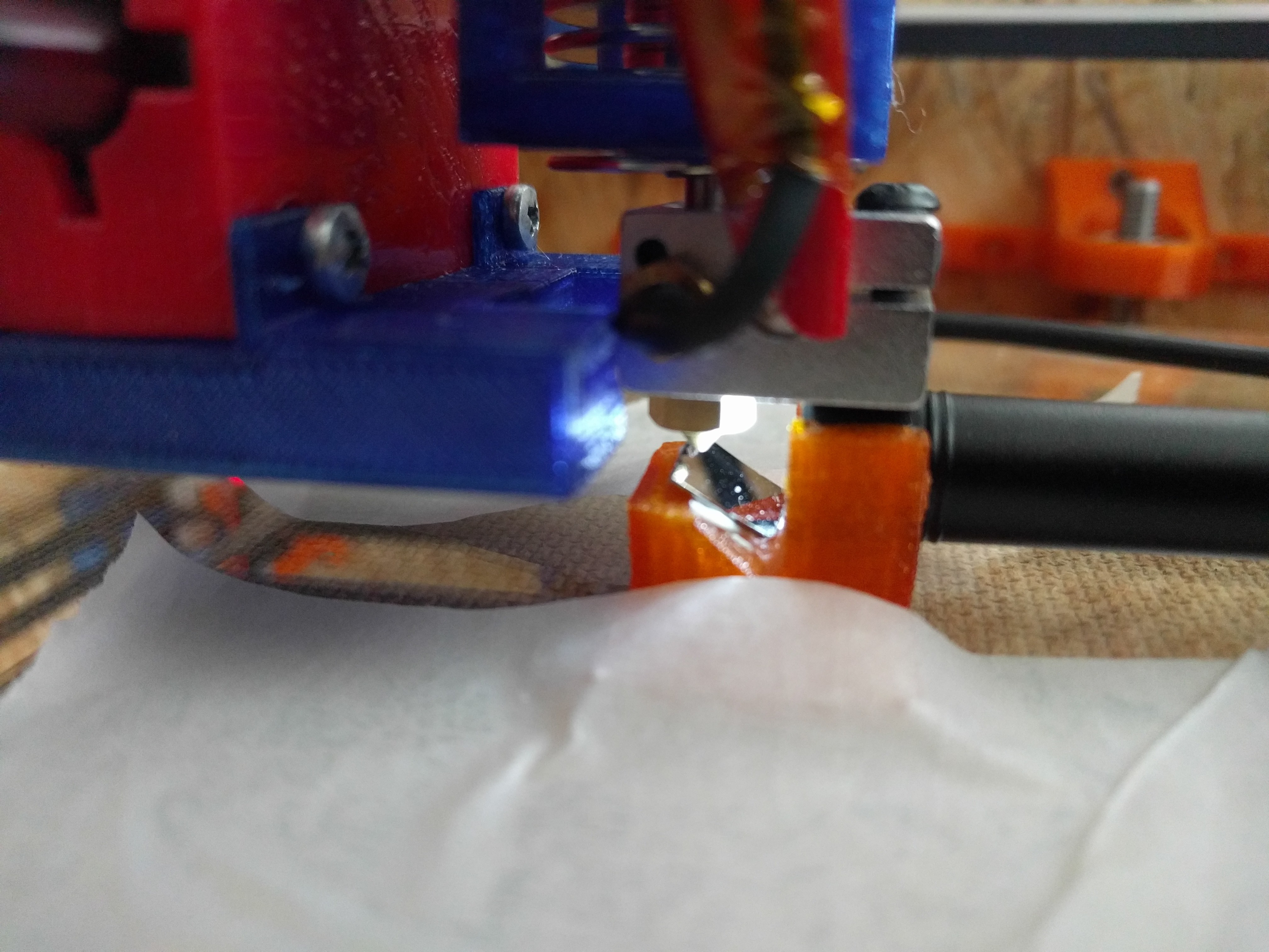
This is how printing looks like now. The short stops after loading are because Cura reduces the hotend temperature (15°C) while it is unused and then needs to wait for the hotend to heat up again. In between the code has been fixed and the pause happens while the nozzle is blocked.
This is the finished part. No prime tower and cleaning. I'm very pleased with the result.
![]()
-
hotend fixture redesign - first moves
08/08/2017 at 13:12 • 0 commentsOtherwise, still fixing minor design issues and busy printing parts.
-
WIP - hotend fixture redesign
08/01/2017 at 07:10 • 0 commentsOne issue that became apparent during the first dual print was oozing. No matter how much I retracted the filament while the hotend was parked, there was always a tiny string oozing out. The dual print only finished because Cura distributes the starting point on the prime tower in each layer. Adding a really large prime tower with thin walls finally did the trick.
![]()
The current design clearly lacks a feature that stops oozing by blocking the nozzle in the parking position. The hotend fixture only provides close control of the pin positions but leaves a lot of slack for the nozzle, which makes it hard (impossible?) to block it. Experiments revealed that entering and leaving the parking position at the same location gives a high chance of picking up oozed filament that was wiped off the nozzle before.
Other issues with the current design are
- the nozzle is slightly deflected by forces applied to the bowden tube
- no space for part cooling fan(s) left
Time for a redesign to address all of these issues.
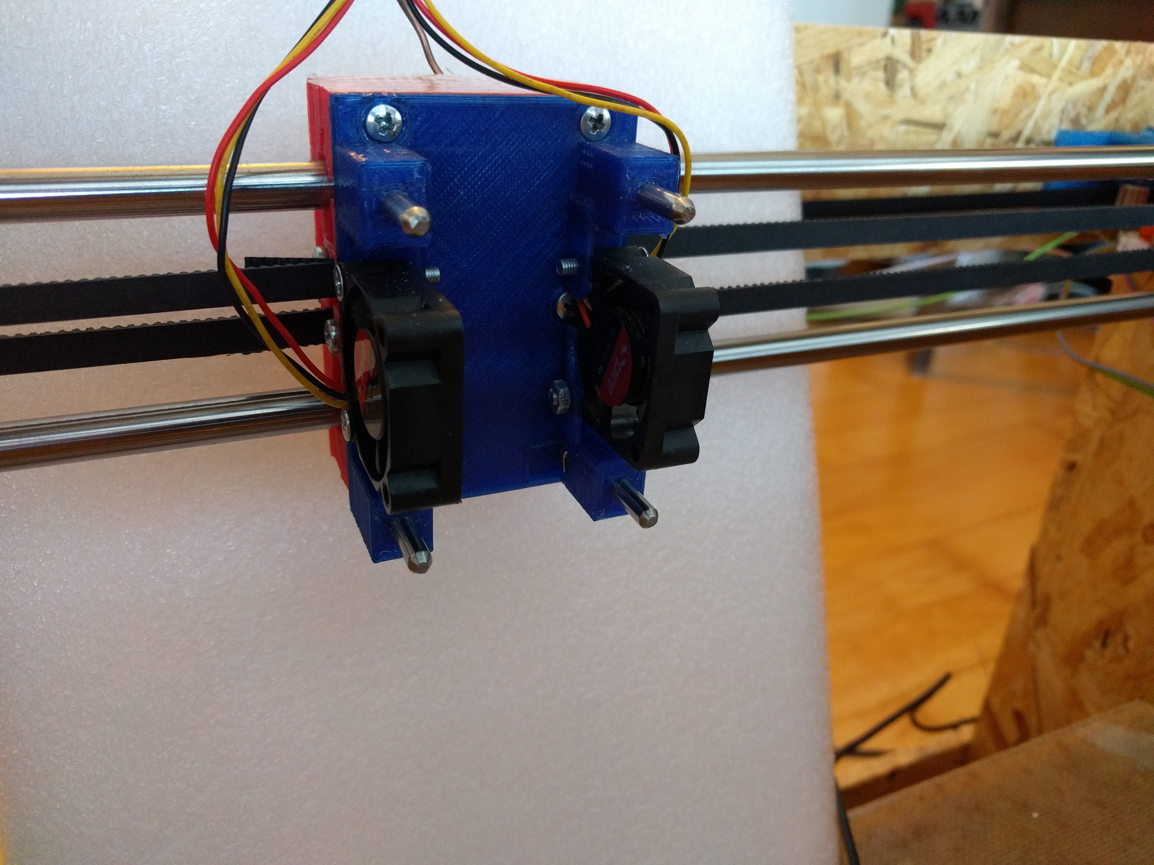
- unidirectional (left to right) load/unload, no risk of picking up oozed filament while unparking
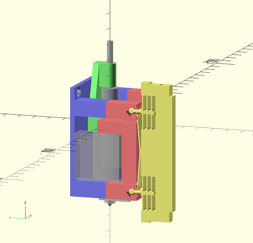
- the parking fixture (yellow) now provides support at the top and bottom
- four instead of two pins/bushings to register the hotend to the carrige
- stress relive for the bowden tube
- space for two 30 mm part cooling fans
![]()
A small plug made out of 350°C silicone should block the nozzle. Not sure if I'm able to cast (more like squeeze) this type of silicone in a mold, if so, adding feature to wipe/clean the nozzle should be easy.
-
Nozzle offset calibration
07/24/2017 at 09:57 • 5 commentsThe first thing to think about when talking about precision is what is actually required. Finally the precision of the whole process is limited by nozzle size and the viscosity of molten plastic. The smallest usable nozzles are 200µm, 1/4 (50µm) of this seemed like good choice of what is required in X and Y. The requirements for Z can be derived from minimum layer height. Objects printed better than 100µm layer height are hardly seen. Again using 1/4 gives 25µm precision in Z.
Neither the printed parts nor off the shelf hotends are manufactured precise enough for these requirements, but Slicers as well as printer firmwares have options to compensate for such errors.
I'm using a low budget USB microscope attached to the build plate to measure the offset of each nozzle. The resolution is in the range of 5µm per pixel, good enough for the requirements.
![]()
A mirror at an angle of 45° is used to get an upwards pointing field of view in the left half of the image, this allows calibration of XY. The right half of the image has a field of view that allows for Z calibration.
![]()
OpenCV and some python scripting are used to extract XY offset and estimate for Z. Instead of relying on camera perspective and resolution, gantry movements and bed height adjustments are used to move the nozzle onto the respective reference points. The calibration is repeatable to about 10-20µm in all three axis.
![]()
Side by side comparison of two hotends after offset calibration (rotated view).
![]()
The process of offset calibration is still a bit tedious, but faster, more reliable and accurate than using thickness gauges and printing variations of vernier scale patters.
Areas for improvement are
- A microscope permanently mounted to the printer, to eg. allow inspection before starting a job.
- Software that closes the loop between loading/unloading tools, measuring offsets, gantry and bed motion
-
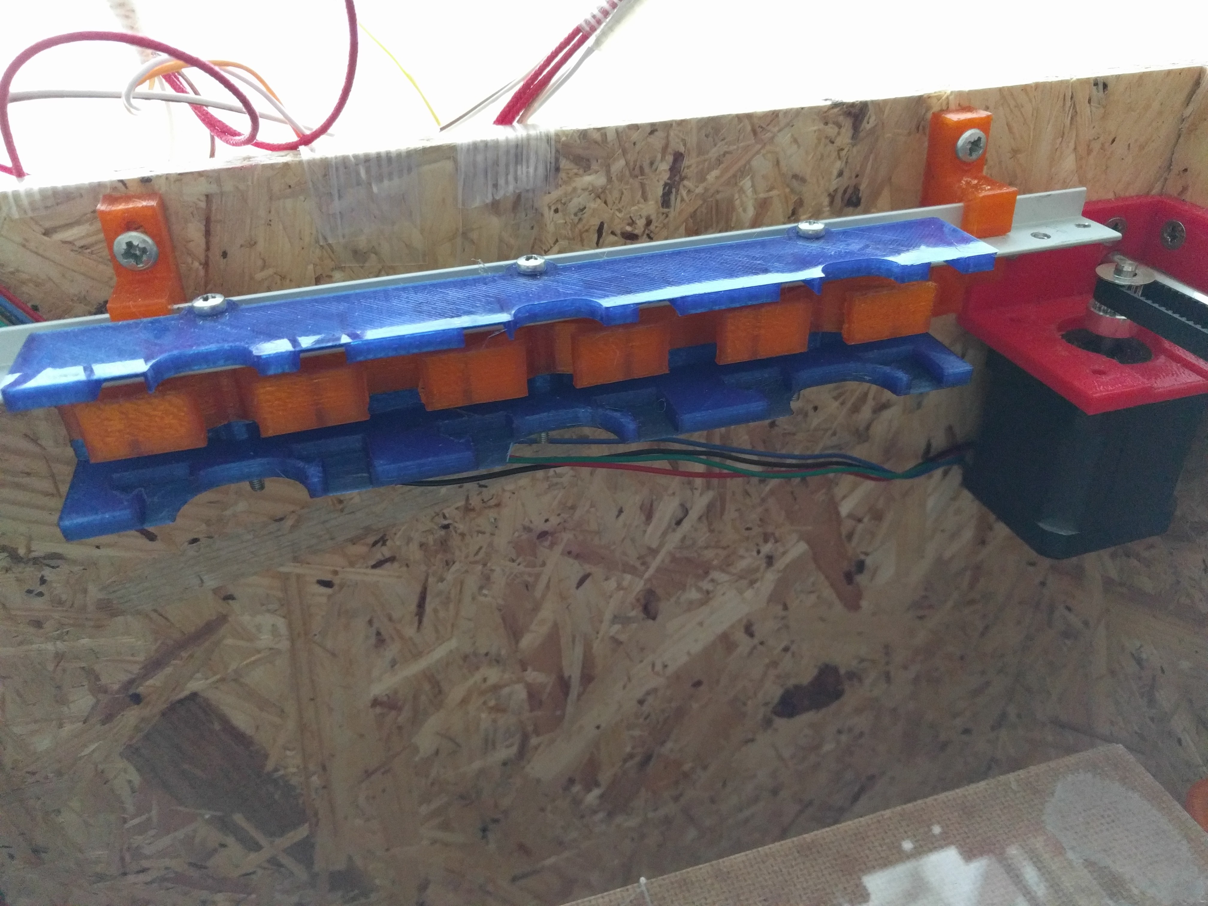
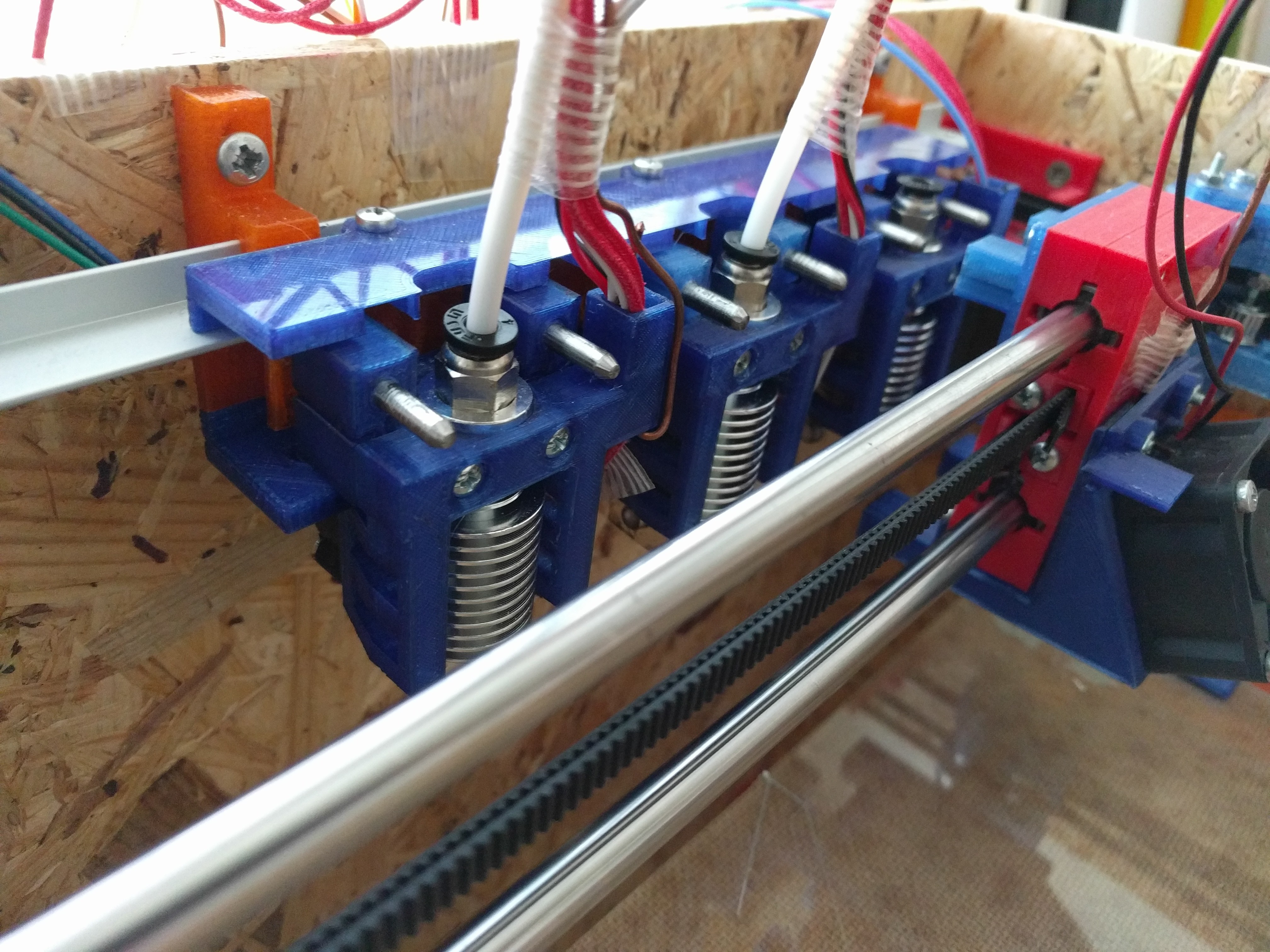
Rest assembly
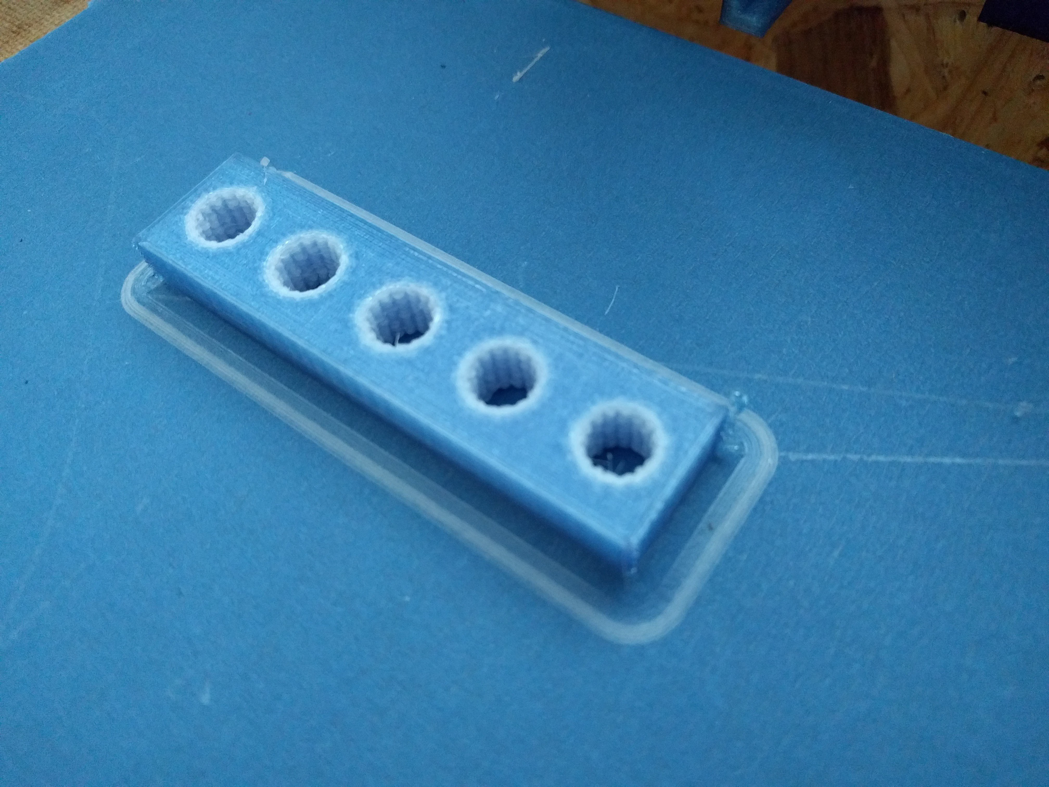
07/23/2017 at 15:28 • 0 commentsRequired parts
- print all parts provided in hotend-rest.stl, PET-G is recommended
- M3 hexnuts and M3x30 bolts as needed
- Aluminium T-Extrusion 15x15mm 1.5mm thick
ToDo's
- height adjustable mounting clamps that fit your specific printer
A parametric design for OpenSCAD with arbitrary amount of positions will be available soon.
![]()
Assembly should be pretty self explanatory, the distance between the screw holes is 60mm.
![]()
Adjust the height of the rest such that it matches the height of the carriage over the whole distance.
![]()
Tool Switching - Multi Extrusion
A scaleable approach to multi extrusion, easy to adopt in most CoreXY/H-Bot printer designs.
 Tool 0, used brass nozzle
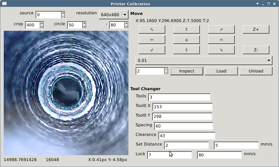
 carriage without hotend
 carriage with hotend