Close
0%
0%

Numitron Hexadecimal display module

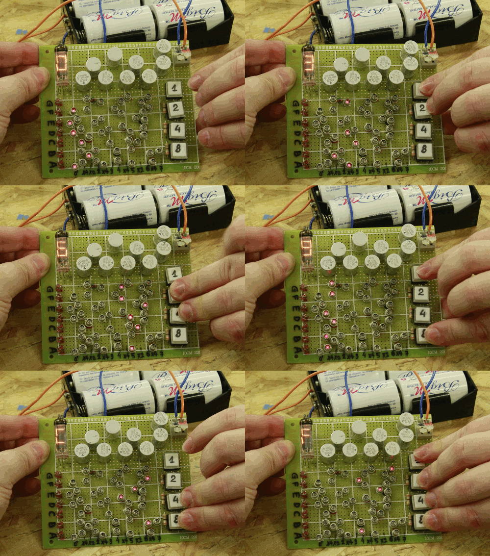
Another hexadecimal display, this one is sans transistor for the extra vintage touch, and uses only Soviet-era parts

Similar projects worth following
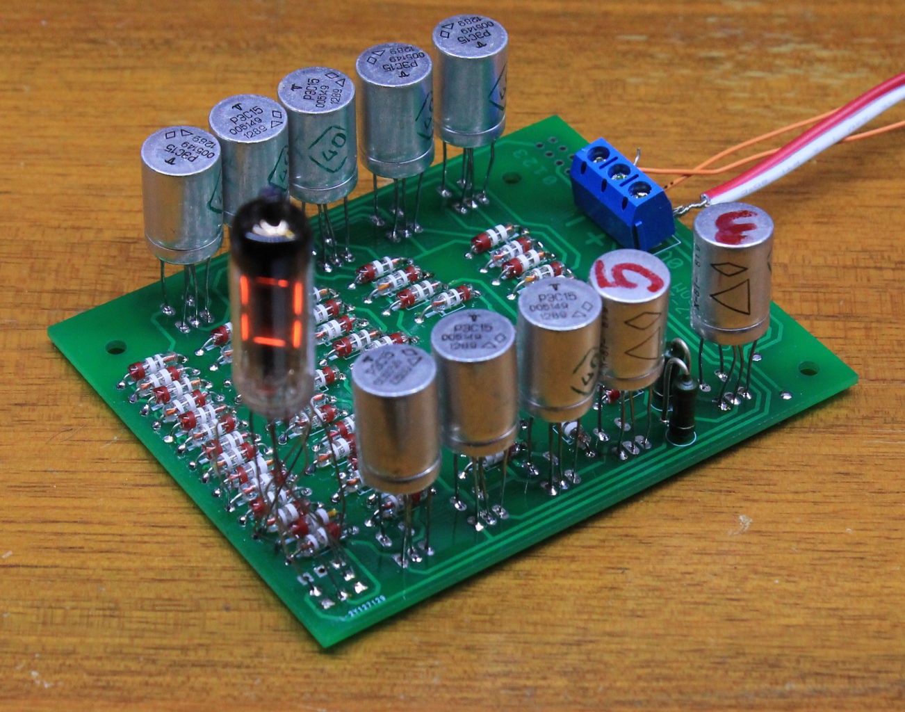
This is another spin-off from the relay-based YGREC project that needs a hexadecimal display. I first thought about using the pretty cool DYPLED module but the sophisticated and cheap module would be out of place. I've chosen Numitron tubes for their incredible vintage look and ease of driving. The hard part is to make a minimal module for decoding a 4-bits bus into the 7-segments display everybody knows and loves...

Specs:
* Supply : 0V, 3.5V, 7V (up to 0.45A, not symmetrical)
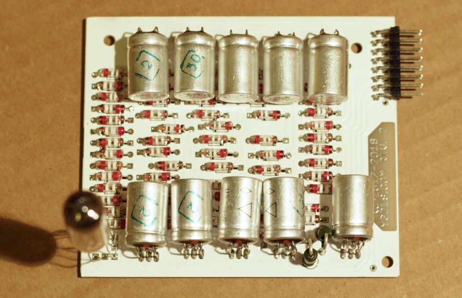
* 10 РЭС15 minirelays, one IV9 display tube and 59 D9K (germanium diodes)
* Decodes 4 bits, from 0 to F
* Input impedance : one relay coil per bit

All files are copyrighted and under https://creativecommons.org/licenses/by-sa/4.0/

2018/08: Project completed !

Digital data display is a recurring and nagging problem when designing DIY computers !

Look at @Artem Kashkanov 's #BrainfuckPC Relay Computer  : it uses VFD tubes but they are driven by semiconductors.
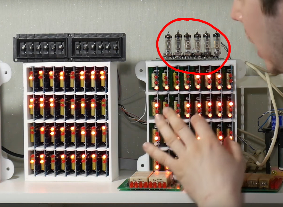
In the case of #YGREC-РЭС15-bis the constraint is to avoid using transistors. This all-Russian neovintage module uses

  • РЭС15 minirelays
  • IV-9 Numitron tubes
  • D9K Soviet germanium diodes

This project is also a continuation of the log 20. Display technology again (yes, another fork !) and I'll move the relevant discussions here.

The logs explain the 3 methods I've invented to keep the parts count low. Some optimisations are pretty neat !
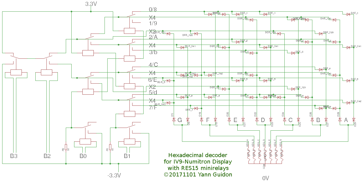
Ideally, like the #DYPLED, I should be able to design and build individual modules for my own use and for eventual #Hackaday TTLers fellows  :-) This would be a step even further than the NUMI-311 (TIL311 module replacement) because of the increased power draw and the increased room. However it will be warmer (both sentimentally and thermally) and you could show a kid the inside "for educational purposes". Who would not want to play with the buttons ?

One design constraint is to keep the input impedance identical and low for all the data bits, to ease integration with other YGREC devices.
Power supplies are derived from experience with the #YGREC-РЭС15-bis so we're using  -3.3V, 0V and 3.3V power rails. Using a single power supply would be too much of a hassle and increase the complexity and the Numitron draws little compared to the relays...


Pinout :
1 b3a b3b
2 b2a b2b
3 b1a b1b
4 b0a b0b
5 V- V-
6 V+ V+
7 0V 0V
8 Zero flag key

Logs:
1. Prior art
2. References
3. Physical configuration
4. Circuit and schematics
5. First prototype and first setback
6. More diodes !
7. Diode optimisation
8. Going further
9. A less preliminary layout
10. A little idea to revive...
11. Another mistake
12. Second valid prototype
13. A new ROM layout generation script
14. Beyond the prototypes
15. PCB
16. The demonstrator goes portable !
17. Enhancements
18. New layout
19. PCB prototype
20. Cascading the LZB
21. PCB delivered !
22. What would the Russians do ?
23. Patched
24. And it works !
25. More boards
26. 5 modules
27. New layout
28. New PCB batch
29. PCB delivered !
30. 10 units
.

HexIV9_201808.sch

Version August 2018 of the schematic (Eagle v7.7.0)

sch - 196.79 kB - 08/18/2018 at 14:04

Download

HexIV9_201808.brd

Version August 2018 of the PCB layout (Eagle v7.7.0)

brd - 90.27 kB - 08/18/2018 at 14:04

Download

RES15_doc000248413.pdf

Russian datasheet of the RES15 relay family. See https://hackaday.io/project/10889/log/37255

Adobe Portable Document Format - 58.02 kB - 04/16/2018 at 03:18

Preview

convo7seg_09.html

Updated script that generates the final ROM configuration (swapping 5 and 6)

HyperText Markup Language (HTML) - 2.74 kB - 10/30/2017 at 17:20

Download

convo7seg_05.html

A script that searches which input permutation saves the most diodes

HyperText Markup Language (HTML) - 3.09 kB - 09/24/2017 at 01:35

Download

  • 10 units

    Yann Guidon / YGDES08/16/2018 at 01:35 2 comments

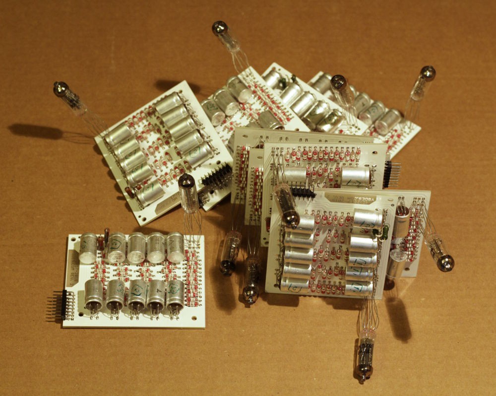
    I soldered the 10 PCB :-)

    The modules work great. I've had only 2 parts wrongly soldered (one reversed diode and one reversed relay) but they were easy to spot.

    The IV-9 are soldered with "loose" pins so they can be adjusted for later mounting.

    All these modules, as well as the 5 pre-series, will be used for the #Hardware assembler / EMUI of the #YGREC8 :-)

  • PCB delivered !

    Yann Guidon / YGDES07/30/2018 at 21:24 0 comments

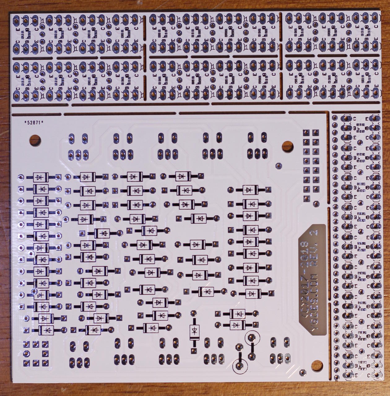
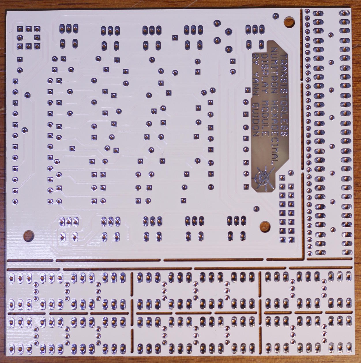
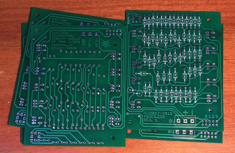
    It took longer than expected (for personal reasons) but they are finally here !

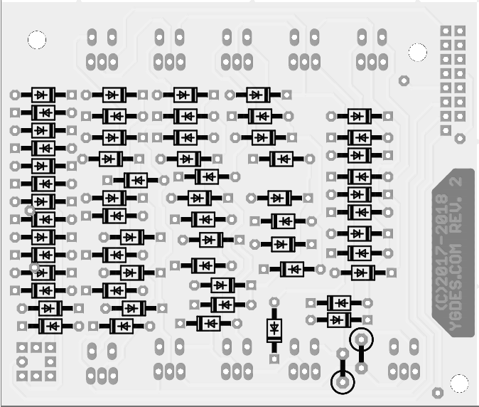
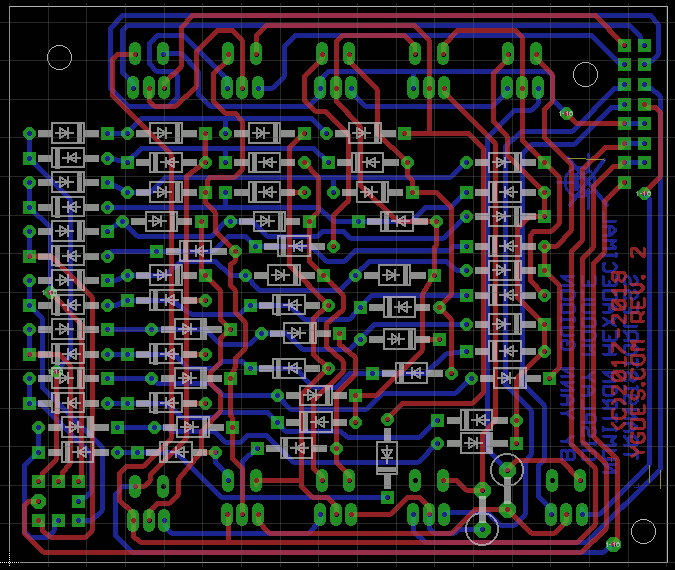
    recto
    verso

    Again I'm glad I used dirtypcbs :) The remaining surface is proto boards for SC70/SOT363 dual transistors used by #YGREC-ECL.

    I must assemble one board so I can build a test rig that will test the 9 other boards.

    All will be used for the #YGREC8's  #Hardware assembler / EMUI as 5 pairs. The 5 prototype boards will be used for an event counter that can go to FFFFFh (so at 30Hz it will wrap around in about 10 hours)


    DAMNED ! I swapped the LSB inputs !

  • New PCB batch

    Yann Guidon / YGDES06/16/2018 at 10:57 0 comments

    Thanks to the Hackaday Prize's seed funds, I've just ordered a new batch of boards.

    The new connector, and the increased solderability, will make this module very easy to build and to use :-)

    Meanwhile, I'm thinking about the use of the first prototype, in the "assembly" panel of #YGREC8:-)

  • New layout

    Yann Guidon / YGDES05/12/2018 at 17:07 0 comments

    Many changes and updates, following the first round of prototypes.

    I changed the connector, a 2×8 0.1" pitch, including a key. It provides data, power and the Z output.

    The Numitron pinout is corrected, at the cost of a couple of vias.

    The board is slightly smaller, 72×85mm now.

    Many pads and drills are adjusted for better soldering.

    I must finish the first tests on the prototypes before I send the new boards to fab.

  • 5 modules

    Yann Guidon / YGDES04/27/2018 at 08:05 0 comments

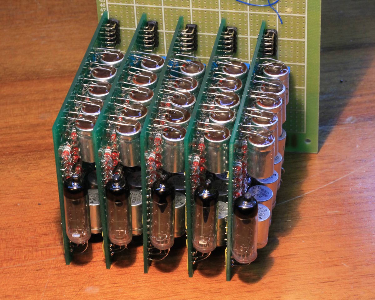
    Soldering was pretty smooth and the 4 other modules are rather easily assembled. They all worked on first power-up !

    So I played with them a bit, to see if the dimensions are good.

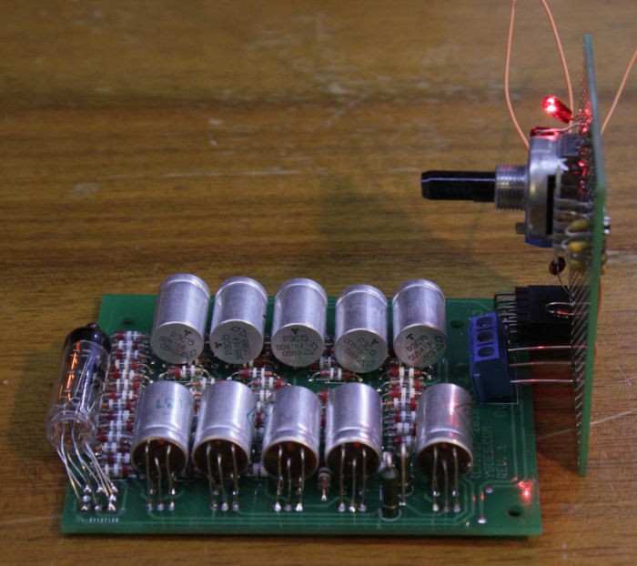
    I finally decided to solder the relays inside, as previously planned, to keep the overall volume low. Reducing the thickness would have increased the total space used by the display...

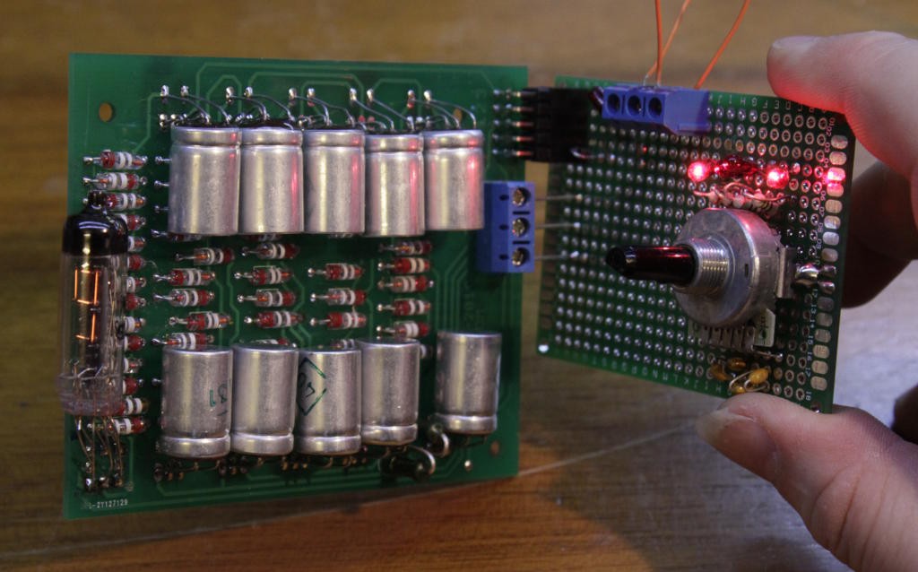
    The result is not as small as I expected but it's still pretty nice !

    Now I have to implement cascading...

  • More boards

    Yann Guidon / YGDES04/23/2018 at 23:41 0 comments

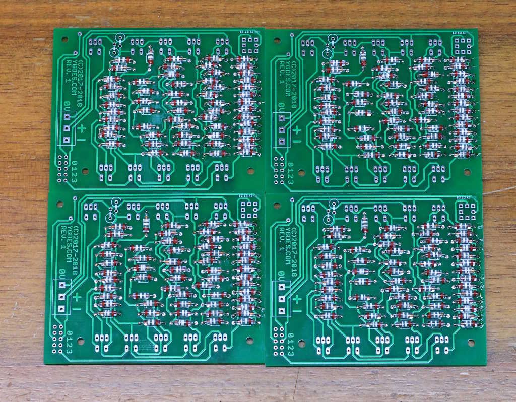
    I prepare the 4 other boards to make a 16-bits display. The diodes are looking good so far.

    This time I'll solder the relays outwards to save a couple of millimeters in thickness.

  • And it works !

    Yann Guidon / YGDES04/22/2018 at 05:49 2 comments

    Here is the module, much closer to the intended format.

    The module is quite larger than initially desired but the thickness is ok, so I can stack several modules and keep the numbers easy to read (with a decent gap between digits).

    After a while, the relays can get warm...

    I had to increase the voltage because some relays wouldn't switch. Strings can get unbalanced so I will have to "bin" the relays ( #ReTest-RPi  is meant to address this). So the module gets up to 3.50V (×2) and F draws up to 0.45A (the power consumption is around 2W). Digit 0 draws quite little.

    The power connector must definitely be redesigned...


    Now, I think that surface in itself is not SUCH an issue and I can make the module thinner by bending the relays outwards/outside. That's the program for the next 4 modules :-)

  • Patched

    Yann Guidon / YGDES04/22/2018 at 02:12 0 comments

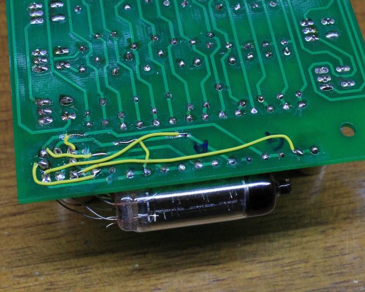
    I patched the traces to let the Numitron sit at a suitable angle, close to what I envisioned in the first logs.

    I'll have to modify the schematic and PCB layout but fortunately it's not a significant change.

    The testing circuit must still be finished, I'm annoyed by the power supply connector. I should use a HE10 header for more than the data.....

  • What would the Russians do ?

    Yann Guidon / YGDES04/14/2018 at 03:13 3 comments

    At two points, a string of 3 coils in series is switched (by another relay) in the middle (that is not high-side or low-side). I expect a significant spike when the contact is released...

    I don't want to waste 2×2 more diodes for the freewheel. They are not free, they use space and they might not stand the repetitive abuse. I prefer a passive approach, using dumb off-the-shelf parts that a Russian engineer might find, decades ago.

    There is not much choice : a capacitor or a resistor...

    A capacitor would be quite expensive, but a 100nF ceramic across the relay's contacts could reduce the dirty HF parasites. However I have no idea how high the voltages could go... And even though the Russians are known for their high-voltage capacitors, it might not be the cheapest approach, particularly if no electrical data is available. And increasing the capacitance will also increase the current spike when the relay closes again...

    So I'm left with resistors. The prototype uses two vintage 1K 1W resistors from Russia. In theory, it would work, even though it adds a bit of quiescent current (6mA×2 ? that's as much as one incandescent segment). The bet is that as the voltage difference increases, the resistor will let more current flow. I should probably measure this on the scope....

    Any advice ? @SHAOS ?

  • PCB delivered !

    Yann Guidon / YGDES04/12/2018 at 12:34 1 comment

    I just received the boards and did a thorough quality check.

    Thank you to the sponsor @Fredrik Högberg !

    It seems that it could be made on bakelite :-)

    Notes for later :

    • PCB trace widths : OK
    • Clearances for mounting holes : OK
    • Clearances for tracks and pads : OK
    • However the pads for the diodes are still too small. I can't even distinguish the round ones from the orthogonal ones. Fortunately there is a silkscreen that shows the diodes' polarity. But for a bakelite/FR2 run, this will be a problem. The 2×5 connector could also be modified, or even changed for a larger pitch.

    Now let's solder one :-)


    More notes :

    • The resistors' pads are too small
    • The diodes spacing is OK and could be tighter
    • I totally messed with the order of the pins of the IV9 when I tried to reverse the order of the segments on the schematic.

    I think I tried to put the Numitron on the other side of the PCB but it didn't work as well as I planned :-(

    After some pin bending, I was able to display 0, 1, 2, 4, 8 but I have to create a PCB to display the rest.

    It's enough to validate the basic system but I must redesign the PCB :-(

View all 30 project logs

Enjoy this project?

Share

Discussions

Yann Guidon / YGDES wrote 07/02/2024 at 23:51 point

https://www.youtube.com/watch?v=YGT1EvmDJh4 is being nasty about Numitrons :-(

  Are you sure? yes | no

Yann Guidon / YGDES wrote 04/25/2018 at 21:40 point

Brian does seem to do a lot of promotion for this side-project, which is pretty unexpected but always welcome :-)
http://hackaday.com/2018/04/25/video-quick-bit-numitrons-and-infinite-build-volumes/
Time to finish the 4 other boards !

  Are you sure? yes | no

Dr. Cockroach wrote 04/25/2018 at 23:02 point

Oh, cool :-D

  Are you sure? yes | no

Yann Guidon / YGDES wrote 04/25/2018 at 21:35 point

And Benchoffed again :-D

  Are you sure? yes | no

Nixie wrote 04/23/2018 at 01:29 point

You got Hackaday'ed ^^

  Are you sure? yes | no

Artem Kashkanov wrote 04/22/2018 at 21:12 point

Hey! I remembered that I have yet another beautiful indicators - Flip-Flop!

And I have 5 of them https://hackaday.io/project/153330-flip-flop-segment-display

  Are you sure? yes | no

Yann Guidon / YGDES wrote 04/22/2018 at 21:17 point

Now you have to make a decoder with diodes and relays.
But unlike incandescent lamps, you'll have a harder time because you need to turn on AND turn off, so the pulses must be in 2 directions...
More diodes, fewer minimisations :-/

  Are you sure? yes | no

Artem Kashkanov wrote 04/22/2018 at 21:19 point

Yep, I found that I already have Diode-relay schematic  for this indicators :) 

But I have no idea when I'll start this project;)

  Are you sure? yes | no

Yann Guidon / YGDES wrote 04/20/2021 at 21:28 point

@Artem Kashkanov  did you start yet ? ;-)

  Are you sure? yes | no

Artem Kashkanov wrote 04/22/2021 at 07:59 point

Not yet

  Are you sure? yes | no

Artem Kashkanov wrote 01/22/2018 at 07:48 point

Wow! So cool indicator, but I couldn't find enough number of them with acceptable price :(  So have to use VF ones.

Interesting schema of BitToSeg encoder - you used two-polar power supply to reduce number of parts?

  Are you sure? yes | no

Yann Guidon / YGDES wrote 01/22/2018 at 07:58 point

Hi ! eBay prices for Numitrons range in the 3-4 USD per piece. Yes it's a bit expensive, more than VFD, but VFD is more complicated due to high voltages.

I have used a symmetrical power supply (2×3.3V) because it's already available in the system I build. I have also made one version with +6V single supply and that uses one more relay to reverse the polarity.

What would you like to do with them ?

  Are you sure? yes | no

Artem Kashkanov wrote 01/22/2018 at 08:08 point

Same as with IV6 - use them for showing current data/address bus states, instruction retired count, etc.

Yeah, +48V requires some additional adjustment logic for controlling them. And you also need 1.2V for heating...

As for the price - I got dekatrons 5USD each... and IV6 for free, so I have no choice but to use VFD ;)

  Are you sure? yes | no

Just4Fun wrote 10/30/2017 at 17:50 point

Cool!!

  Are you sure? yes | no

Yann Guidon / YGDES wrote 11/01/2017 at 21:44 point

And it's only the beginning :-)

  Are you sure? yes | no

Similar Projects

Does this project spark your interest?

Become a member to follow this project and never miss any updates