-
10 units
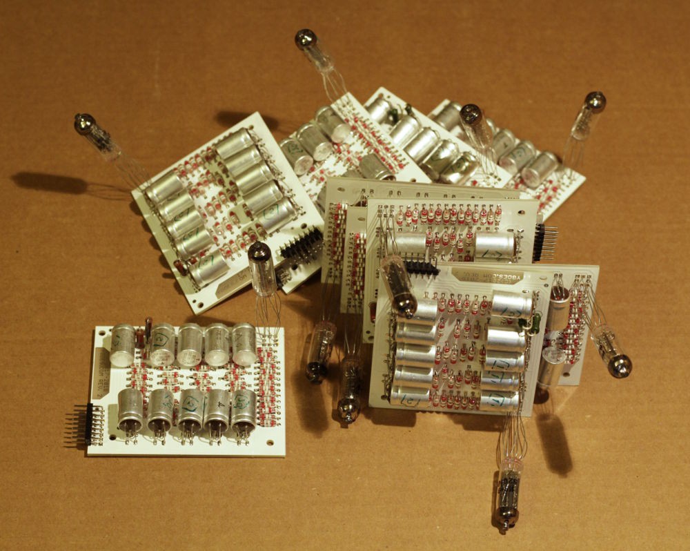
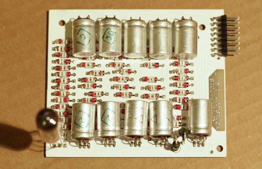
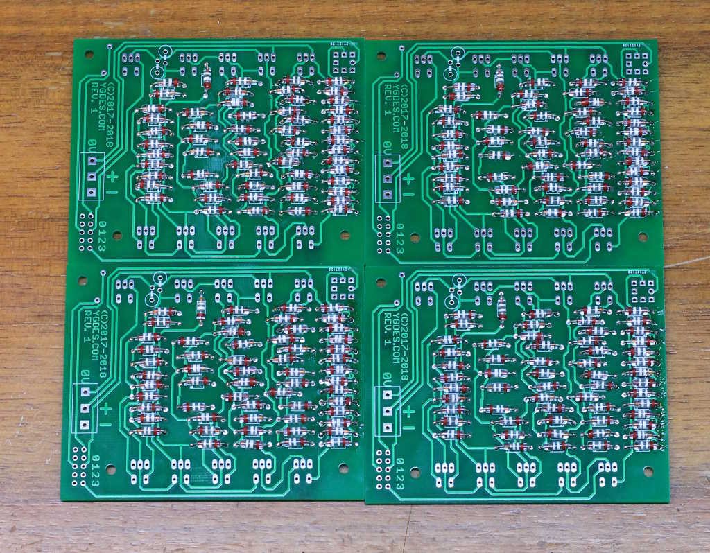
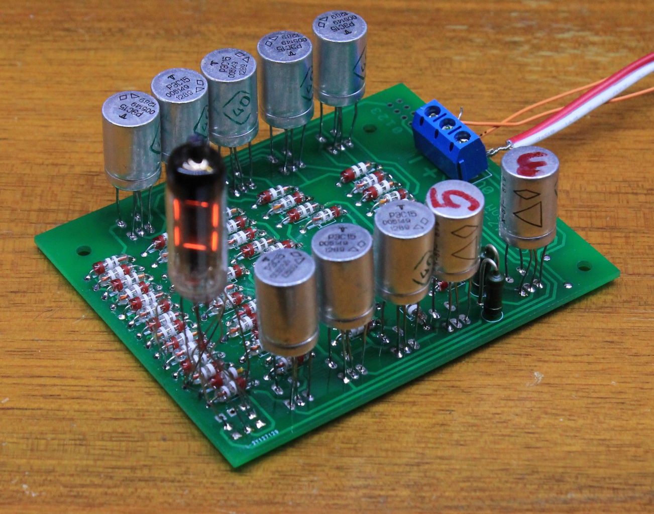
08/16/2018 at 01:35 • 2 commentsI soldered the 10 PCB :-)
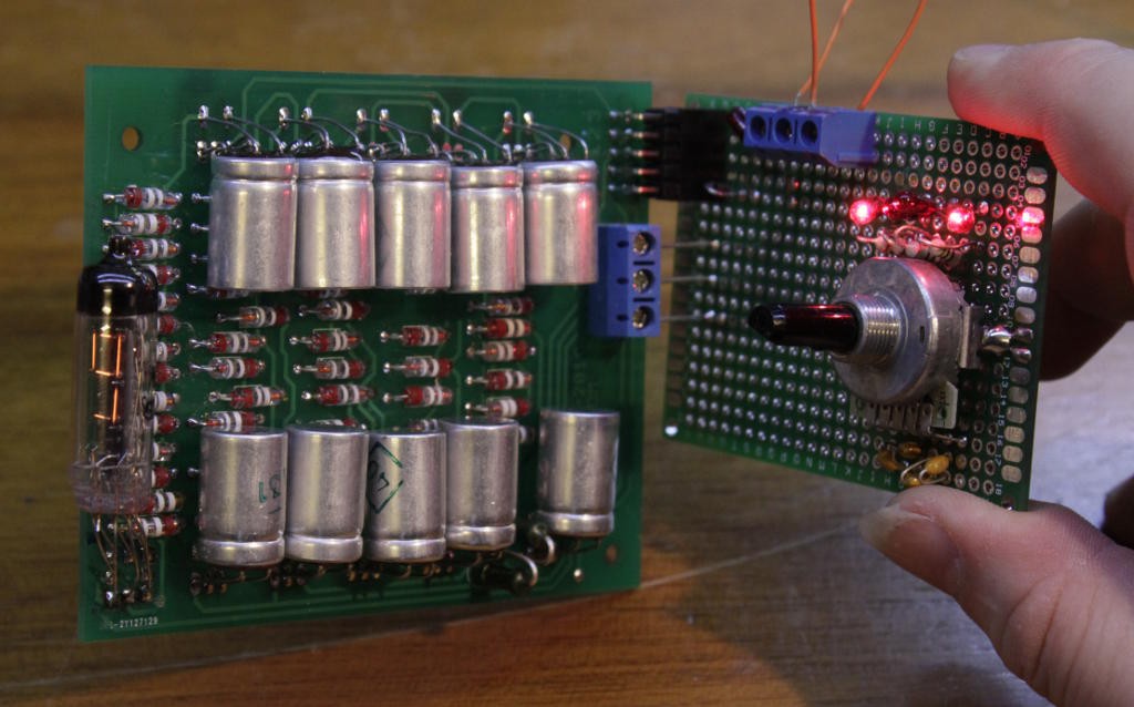
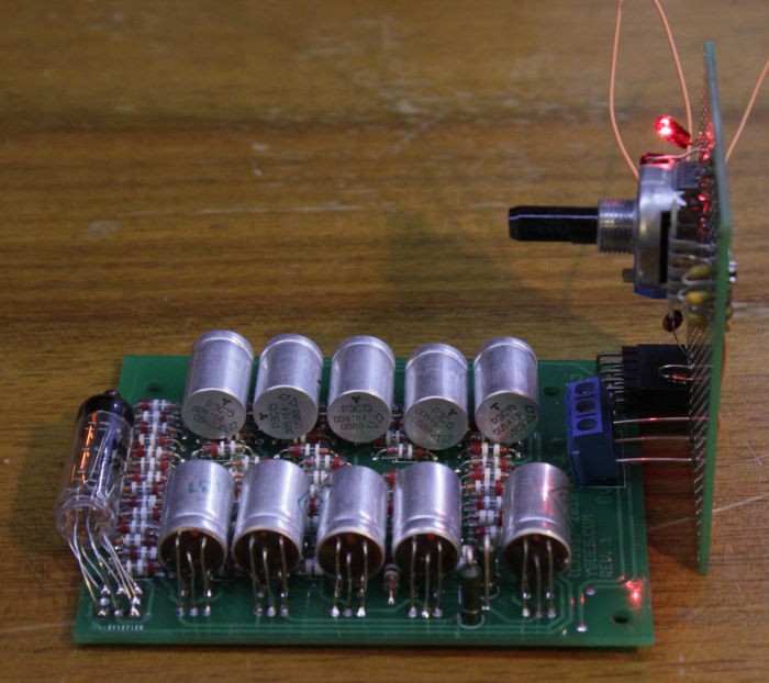
The modules work great. I've had only 2 parts wrongly soldered (one reversed diode and one reversed relay) but they were easy to spot.
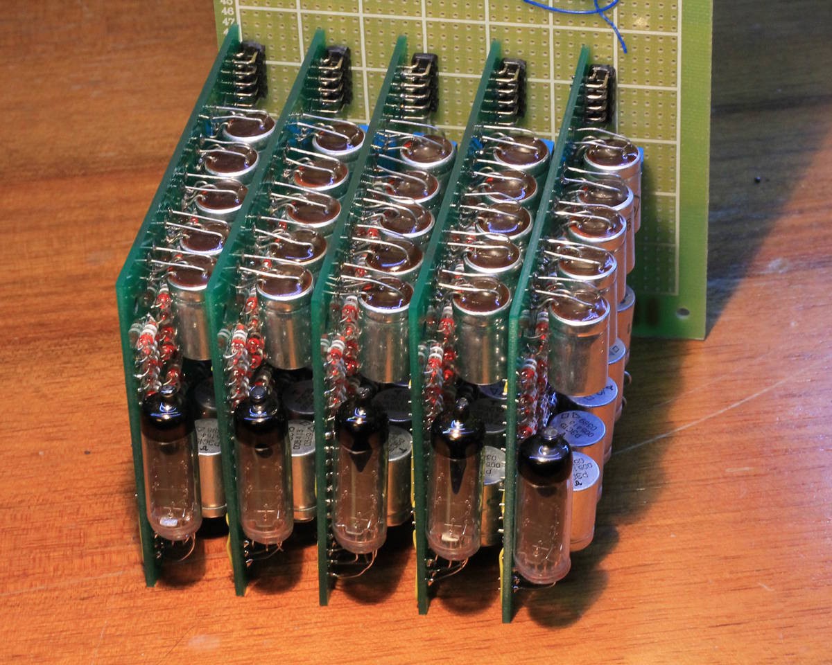
The IV-9 are soldered with "loose" pins so they can be adjusted for later mounting.
All these modules, as well as the 5 pre-series, will be used for the #Hardware assembler / EMUI of the #YGREC8 :-)
-
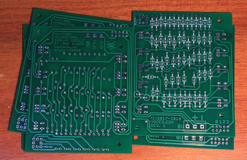
PCB delivered !
07/30/2018 at 21:24 • 0 commentsIt took longer than expected (for personal reasons) but they are finally here !
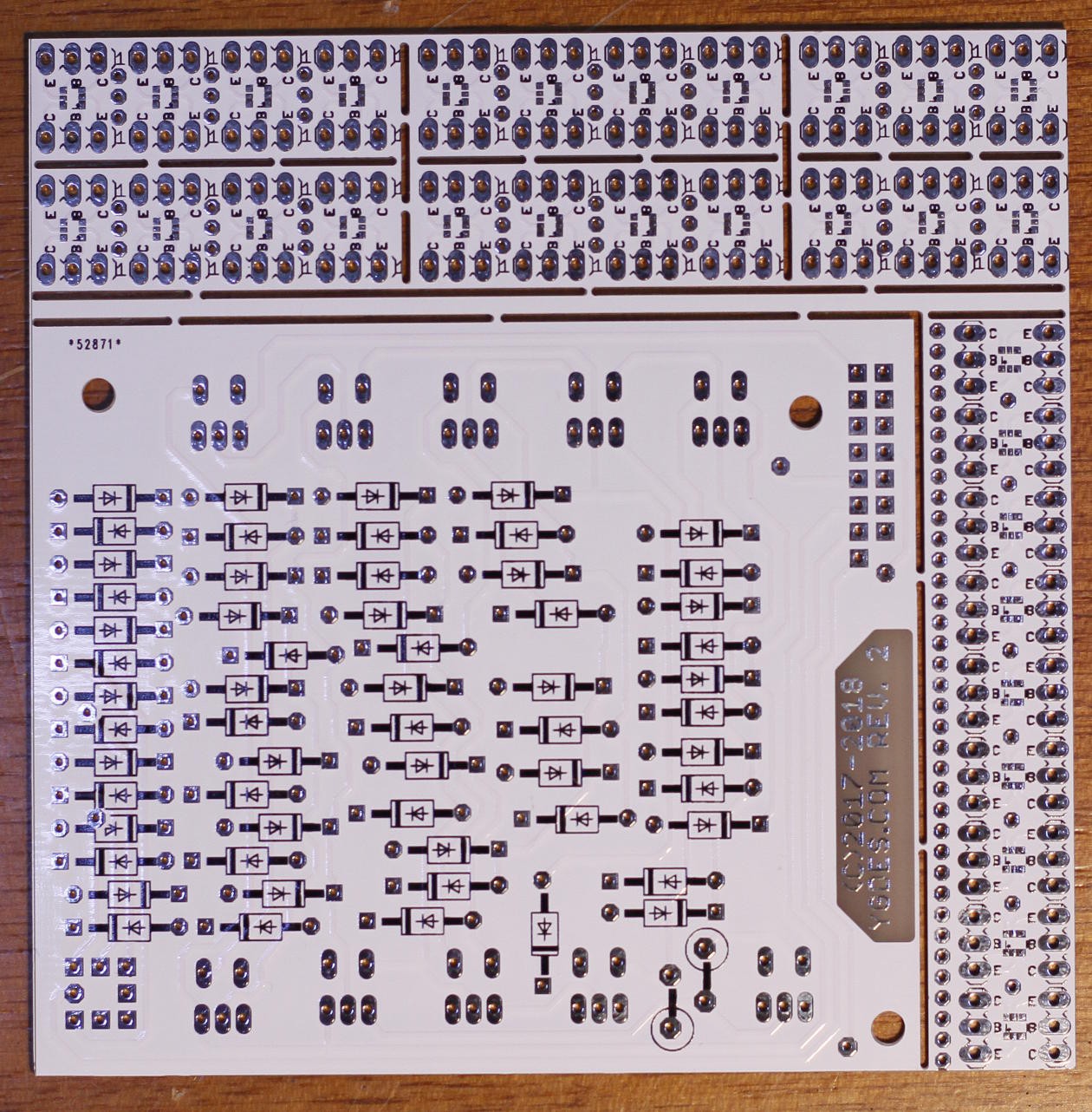
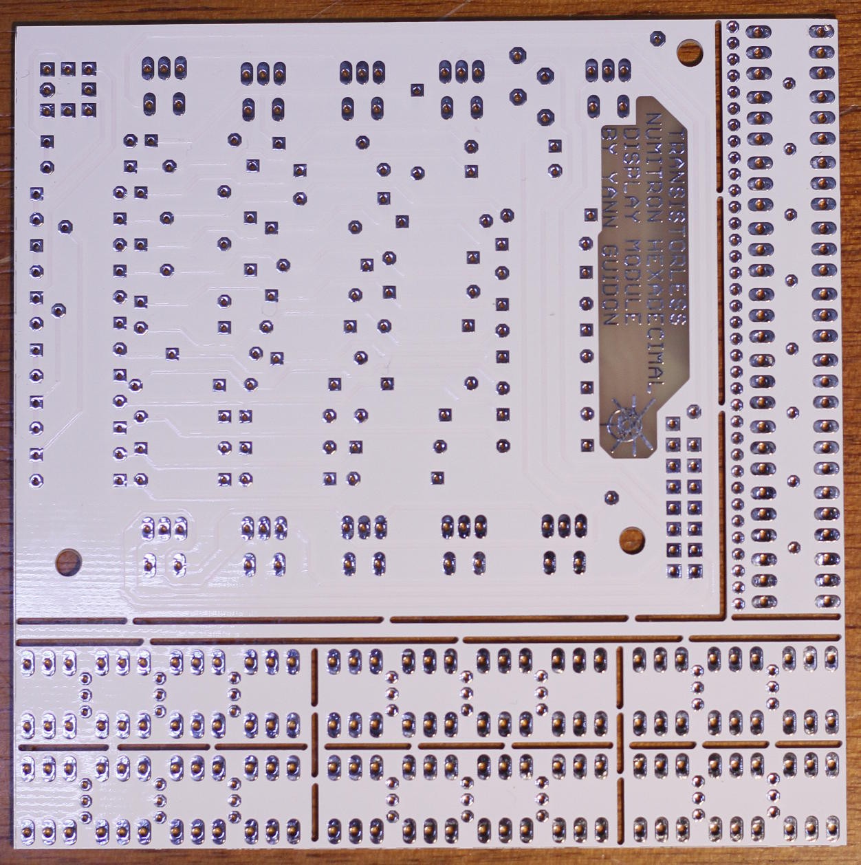
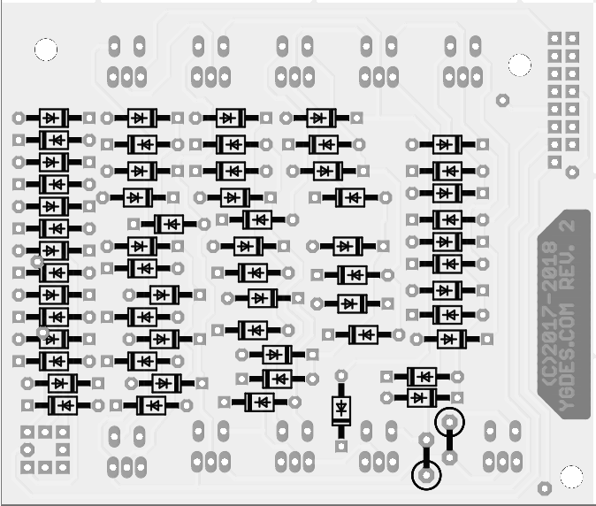
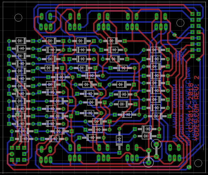
recto verso Again I'm glad I used dirtypcbs :) The remaining surface is proto boards for SC70/SOT363 dual transistors used by #YGREC-ECL.
I must assemble one board so I can build a test rig that will test the 9 other boards.
All will be used for the #YGREC8's #Hardware assembler / EMUI as 5 pairs. The 5 prototype boards will be used for an event counter that can go to FFFFFh (so at 30Hz it will wrap around in about 10 hours)
DAMNED ! I swapped the LSB inputs ! -
New PCB batch
06/16/2018 at 10:57 • 0 commentsThanks to the Hackaday Prize's seed funds, I've just ordered a new batch of boards.
![]()
The new connector, and the increased solderability, will make this module very easy to build and to use :-)
Meanwhile, I'm thinking about the use of the first prototype, in the "assembly" panel of #YGREC8:-)
-
New layout
05/12/2018 at 17:07 • 0 commentsMany changes and updates, following the first round of prototypes.
![]()
I changed the connector, a 2×8 0.1" pitch, including a key. It provides data, power and the Z output.
The Numitron pinout is corrected, at the cost of a couple of vias.
The board is slightly smaller, 72×85mm now.
Many pads and drills are adjusted for better soldering.
I must finish the first tests on the prototypes before I send the new boards to fab.
-
5 modules
04/27/2018 at 08:05 • 0 commentsSoldering was pretty smooth and the 4 other modules are rather easily assembled. They all worked on first power-up !
So I played with them a bit, to see if the dimensions are good.
I finally decided to solder the relays inside, as previously planned, to keep the overall volume low. Reducing the thickness would have increased the total space used by the display...
The result is not as small as I expected but it's still pretty nice !
Now I have to implement cascading...
-
More boards
04/23/2018 at 23:41 • 0 commentsI prepare the 4 other boards to make a 16-bits display. The diodes are looking good so far.
This time I'll solder the relays outwards to save a couple of millimeters in thickness.
-
And it works !
04/22/2018 at 05:49 • 2 commentsHere is the module, much closer to the intended format.
The module is quite larger than initially desired but the thickness is ok, so I can stack several modules and keep the numbers easy to read (with a decent gap between digits).
After a while, the relays can get warm...
I had to increase the voltage because some relays wouldn't switch. Strings can get unbalanced so I will have to "bin" the relays ( #ReTest-RPi is meant to address this). So the module gets up to 3.50V (×2) and F draws up to 0.45A (the power consumption is around 2W). Digit 0 draws quite little.
The power connector must definitely be redesigned...
Now, I think that surface in itself is not SUCH an issue and I can make the module thinner by bending the relays outwards/outside. That's the program for the next 4 modules :-) -
Patched
04/22/2018 at 02:12 • 0 commentsI patched the traces to let the Numitron sit at a suitable angle, close to what I envisioned in the first logs.
I'll have to modify the schematic and PCB layout but fortunately it's not a significant change.
The testing circuit must still be finished, I'm annoyed by the power supply connector. I should use a HE10 header for more than the data.....
-
What would the Russians do ?
04/14/2018 at 03:13 • 3 commentsAt two points, a string of 3 coils in series is switched (by another relay) in the middle (that is not high-side or low-side). I expect a significant spike when the contact is released...
I don't want to waste 2×2 more diodes for the freewheel. They are not free, they use space and they might not stand the repetitive abuse. I prefer a passive approach, using dumb off-the-shelf parts that a Russian engineer might find, decades ago.
There is not much choice : a capacitor or a resistor...
A capacitor would be quite expensive, but a 100nF ceramic across the relay's contacts could reduce the dirty HF parasites. However I have no idea how high the voltages could go... And even though the Russians are known for their high-voltage capacitors, it might not be the cheapest approach, particularly if no electrical data is available. And increasing the capacitance will also increase the current spike when the relay closes again...
So I'm left with resistors. The prototype uses two vintage 1K 1W resistors from Russia. In theory, it would work, even though it adds a bit of quiescent current (6mA×2 ? that's as much as one incandescent segment). The bet is that as the voltage difference increases, the resistor will let more current flow. I should probably measure this on the scope....
Any advice ? @SHAOS ?
-
PCB delivered !
04/12/2018 at 12:34 • 1 commentI just received the boards and did a thorough quality check.
Thank you to the sponsor @Fredrik Högberg !
It seems that it could be made on bakelite :-)
Notes for later :
- PCB trace widths : OK
- Clearances for mounting holes : OK
- Clearances for tracks and pads : OK
- However the pads for the diodes are still too small. I can't even distinguish the round ones from the orthogonal ones. Fortunately there is a silkscreen that shows the diodes' polarity. But for a bakelite/FR2 run, this will be a problem. The 2×5 connector could also be modified, or even changed for a larger pitch.
Now let's solder one :-)
More notes :
- The resistors' pads are too small
- The diodes spacing is OK and could be tighter
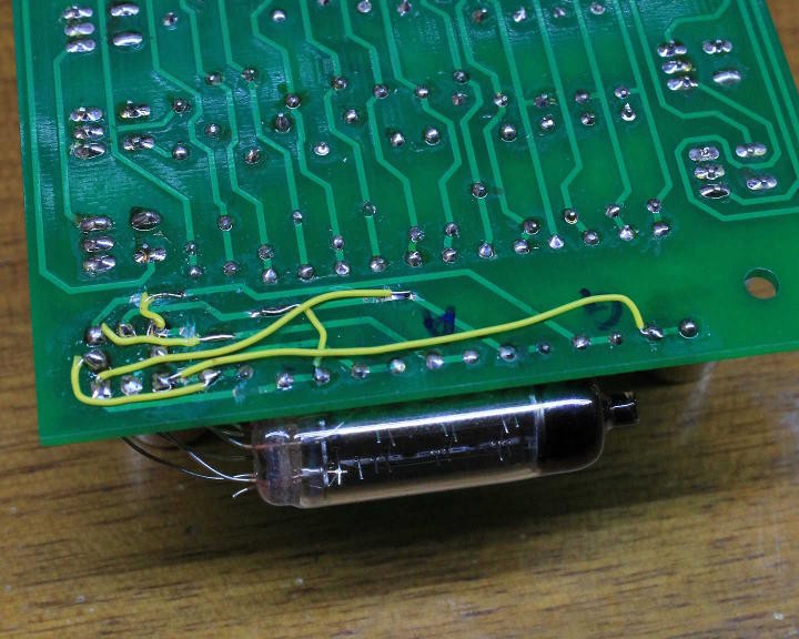
- I totally messed with the order of the pins of the IV9 when I tried to reverse the order of the segments on the schematic.
I think I tried to put the Numitron on the other side of the PCB but it didn't work as well as I planned :-(
After some pin bending, I was able to display 0, 1, 2, 4, 8 but I have to create a PCB to display the rest.
It's enough to validate the basic system but I must redesign the PCB :-(
Numitron Hexadecimal display module
Another hexadecimal display, this one is sans transistor for the extra vintage touch, and uses only Soviet-era parts
 Yann Guidon / YGDES