Nelson Phillips
-
Generalisation
07/03/2018 at 12:45 • 0 commentsAs this projects original motivation, apart from an interesting soft robotic project, was to participate in the HaD Prize. As it didn't get to a stage of completion I was happy with a shift in direction is needed to further participation in the prize. So to fulfill the surprisingly narrow criteria of Human - Computer interfacing this shift would need to go back to the principles of soft robotic and its origins of social robotics to find the hook needed to continue. I must note that this is not necessarily a bad thing as the reasons I found soft robotics interesting is the interesting human and computer interactions. Essentially this is placing greater emphasis on how the soft robotic system conveys information rather than the previous emphasis of filtering the noisy environment.
What this means.
Firstly finishing off the mold design concept. The mold design up until here had the actuators on one side of the mold which meant that the end product could only flex in one direction. This means that it really is not totally flexible and modular process and the sections cast were limited. In reality the each section could be glued together but, that goes against the principle of the concept.
So this is done and
![]()
![]()
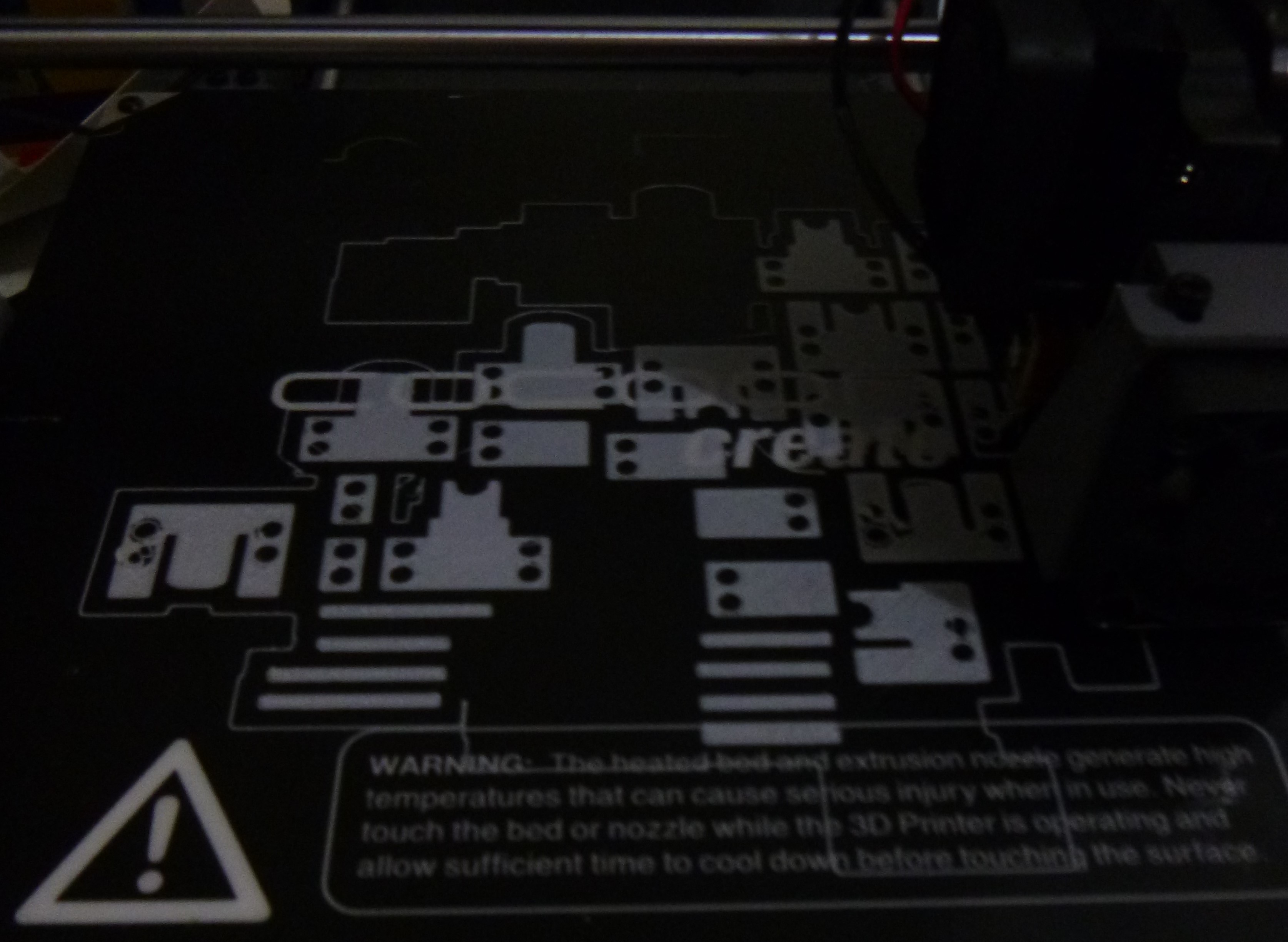
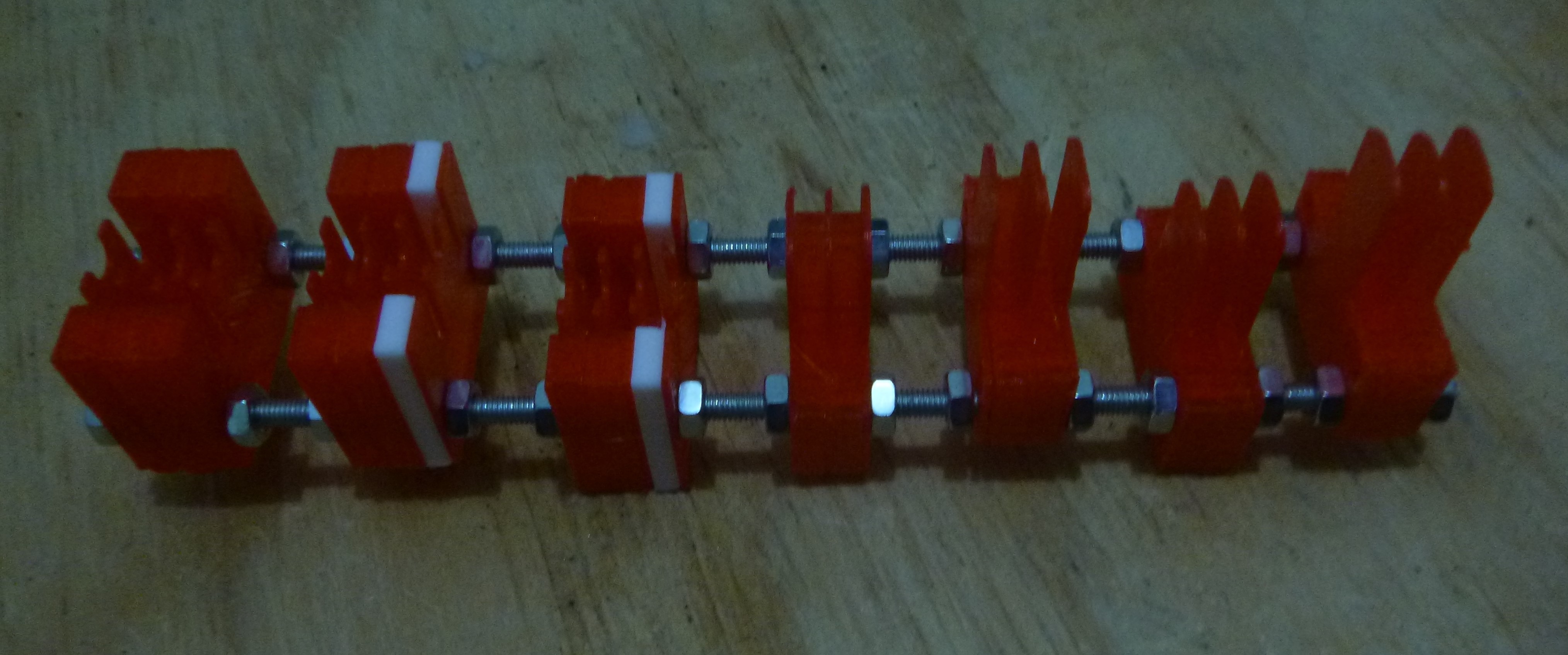
the above picture shows the mold, upside down, with the first part the upside down actuator, the second is typical, the third flexes toward and finally the last away.
The outcome should be a section with an ability to reach in all directions. In theory it could replicate a elephants trunk or a caterpillar. As this project is projecting towards human computer interface then this selves as the interface and requires more than just the mechanical interface of the soft actuator. The nodule at the front is the first step into making this actuator more of a sensor mechanism.
-
Cockup Part 1
06/04/2018 at 12:44 • 0 commentsKnowing that I was behind and that soft actuators are difficult to get right I knew I was highly unlikely to finish to the level need to meet the Robotics Module Challenge. So this being a bit disappointing the first iteration through the first pour came with the first problems that need fixing. However, there is a couple of successful aspect that should not be ignored and they are the method of fixing the actuator to the exoskeleton worked well. Generally the mold also worked well the only adjustments will be to fix the mechanical properties of the actuator not the concept of a flexible modular mold creation system.
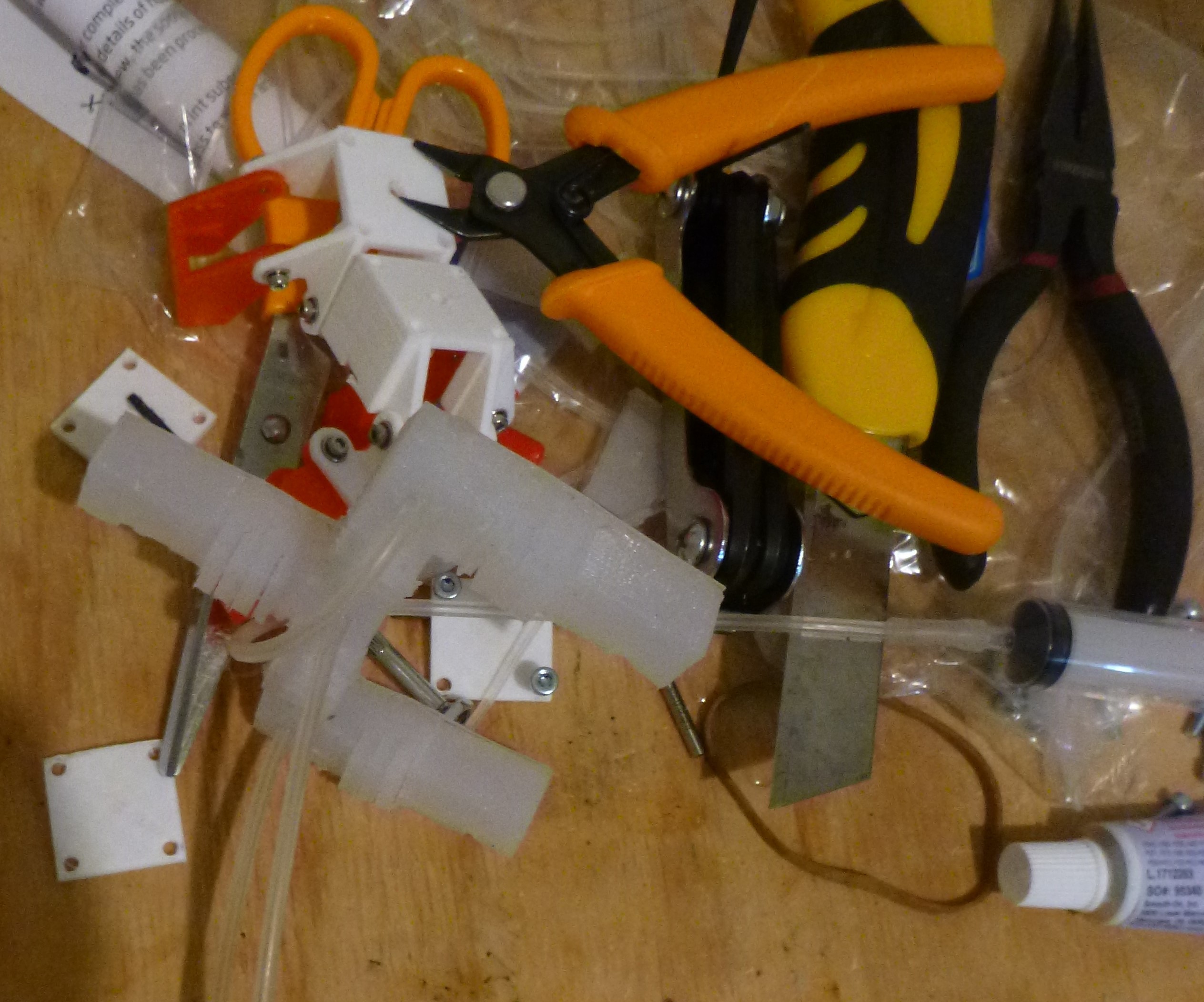
![]()
Among this detritus of disaster is a couple of solutions. To how the actuator interacts with the exoskeleton and generally how the actuator exits the mold and assembles.
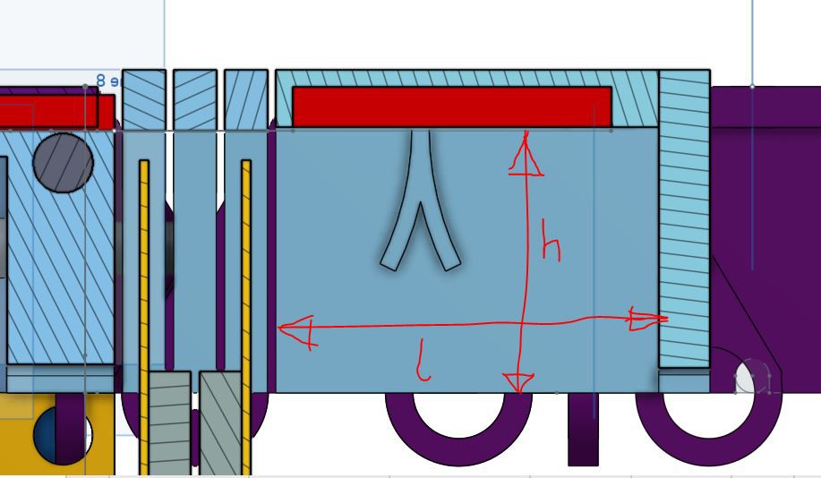
- The interaction between the exoskeleton and the actuator requires the axis and the neutral axis having similar centres. If they do not then there is added stress in the actuator and the performance is significantly reduce. Above the sections have had the top few millimeters removed so the actuator sits further up into the exoskeleton. An adjustment to the between sections of the mold will have the inner roof lowered (h) and for other reasons the length (l) will also be reduced to counter the 3D print overflow.
- The tube attachment holes need realigning for the previous adjustments but, also the size of the holes could be a little bigger just for ease of assembly.
![]()
Without these adjustment a working actuator could be achieved however the aim was to have a working model by the end of the robotics challege as this isn't going to happen the adjustment to the mold will be made first then a better model should be achieved anyway. Also the molds will not be released until they produce a better outcome. In the mean time the drawing provided can be used to reproduce for the actuators and the released exoskeleton CAD files.
-
Build. Part 1.
06/03/2018 at 12:23 • 0 commentsChose a module pattern to assemble and document. Would have liked to be further into this project here but, meh, what can be done.
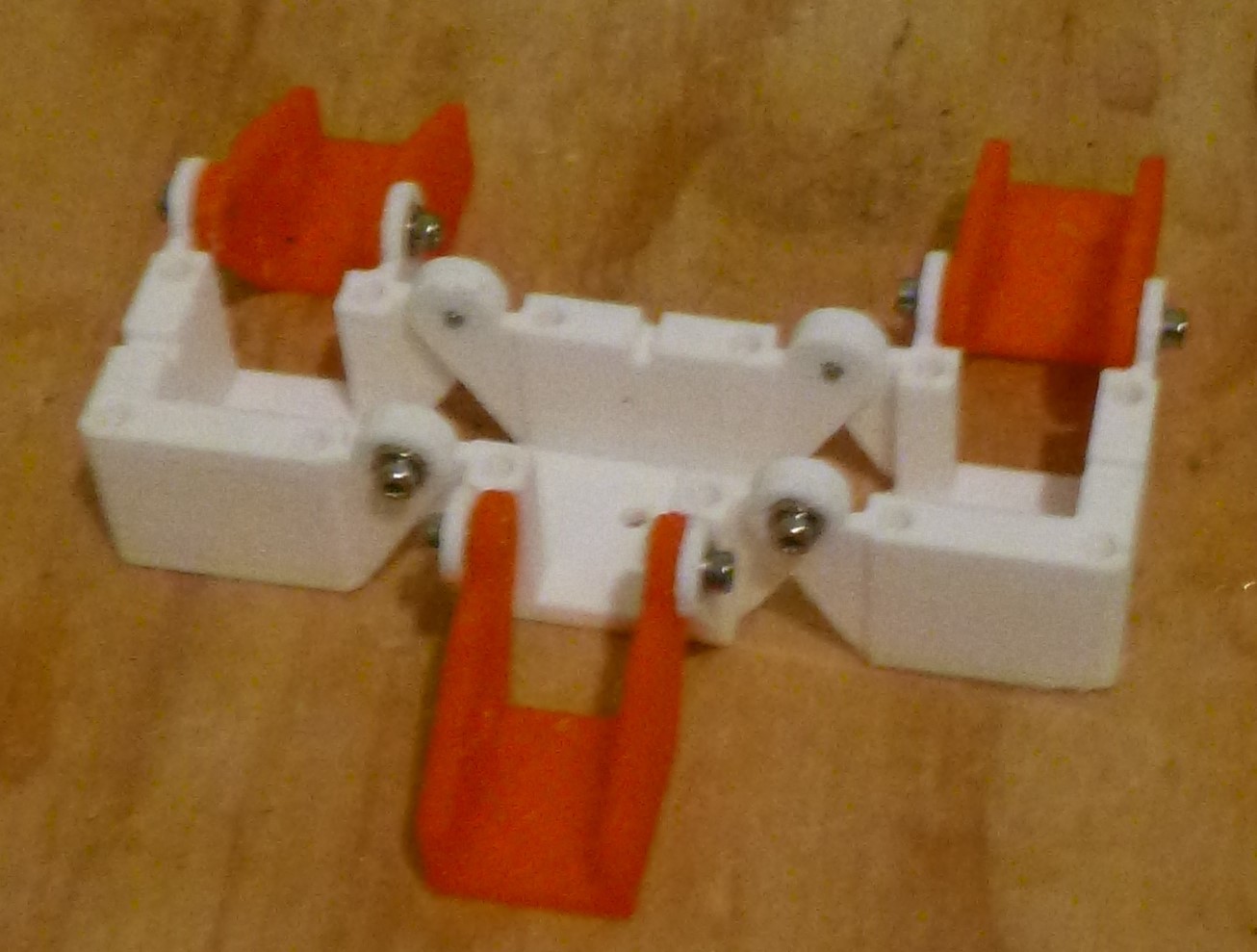
The choice of module expresses the concept of this project the best. It has an amount of complexity that this modular concept was designed for and the possibility of unique robotic interactions.
![]()
The mold produced a reasonably good result. Despite the complexity of the mold the flexibility should pay off with an almost infinite range of mold and actuator that could be produced. In reality this could be the outcome of this project with a modular actuator produced in assembly.
![]()
Actuator sitting on the top of a 0.5mm 50A shore silicone sheet for the flexure. This carry on from a previous project to definitely the right solution for these types of soft silicone actuator as it provides a certain bend.
![]()
Tracing out the flexure in the silicone sheet.
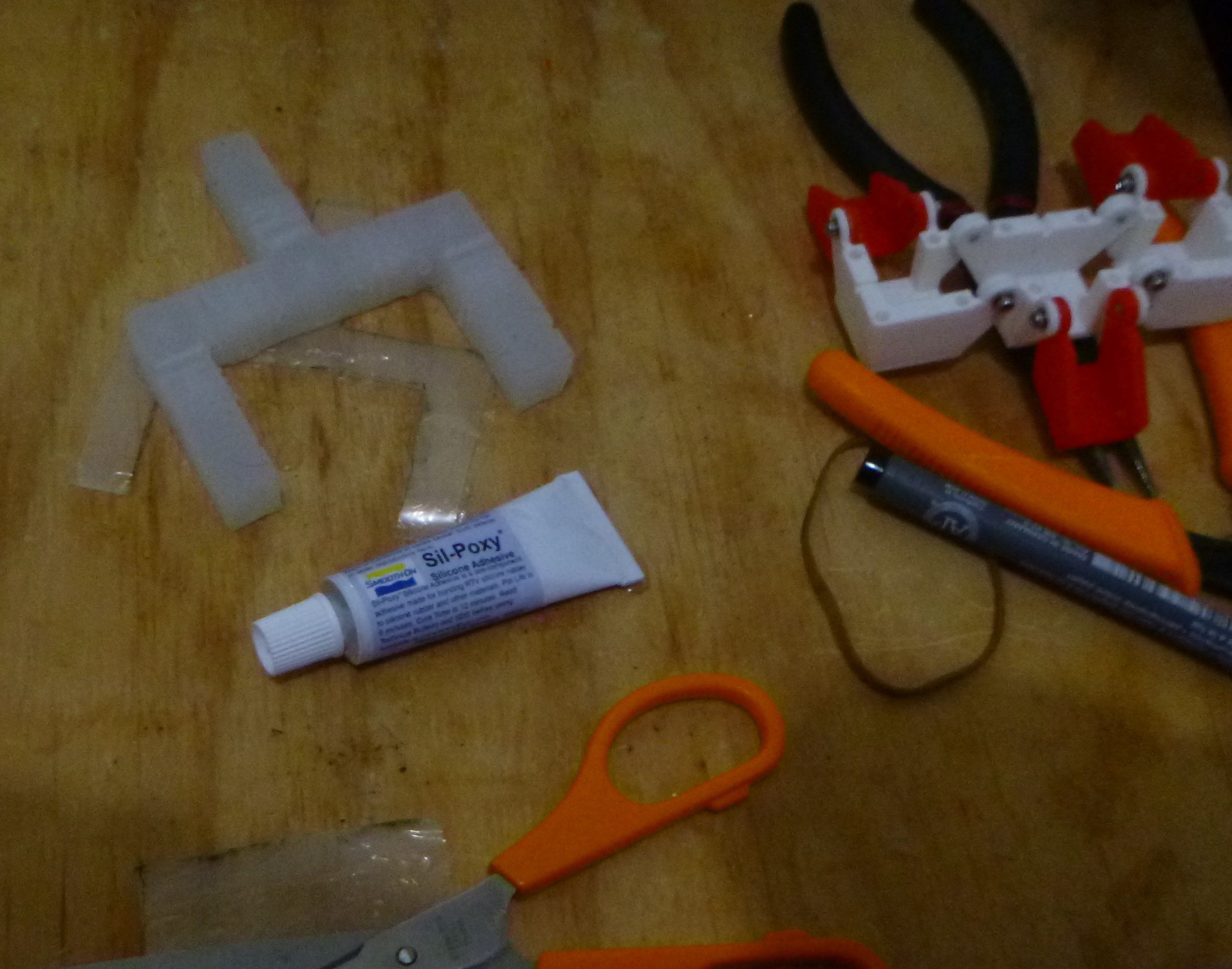
![]()
Gluing the silicone sheet to the actuator.
![]()
Then comes the final stage of the build. inserting the tubes and testing the projects assumptions to see if this project actually has some legs.
-
Mold Building
05/27/2018 at 10:55 • 0 commentsThis isn't going as well as I was hoping, to many thing and not enough spare time.
The premise of this project was to significantly improve the mold for the silicone actuator. Deconstructing the mold and individually improving part of the molds and then combining them into a flexible and modular system. Having done this in CAD it was a matter of printing them out to see how they reproduce.
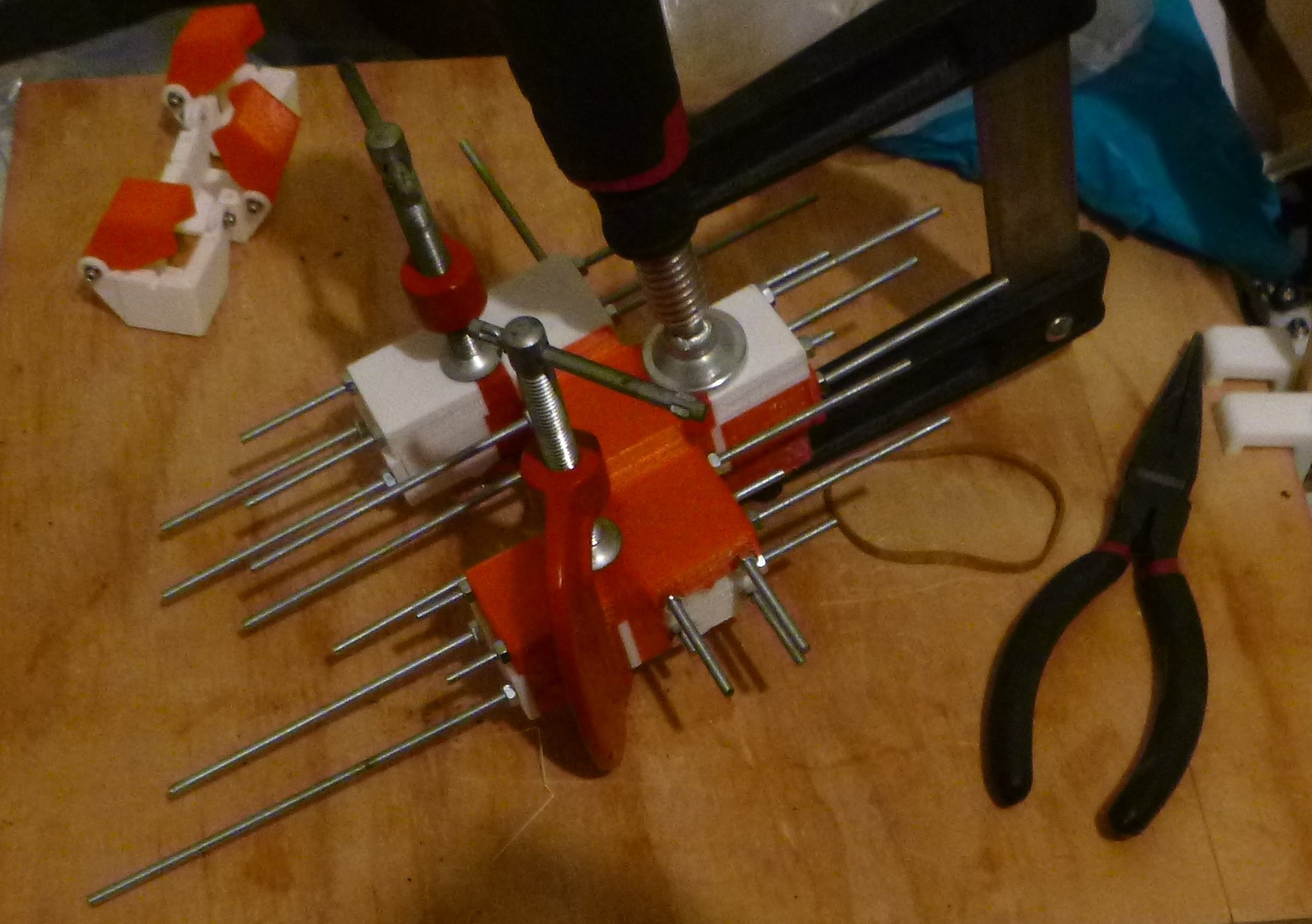
The most significant improvement is the internal and external dividing parts. These are where all(most) the improvement comes from, by reducing their length and minimizing the size and increasing the response of actuation. If printing them from bottom to top the minimum length is about 0.8+mm and fragile, ideally they would want to be 0,2mm but more realistically 0.5mm. Laying them flat was my solution for printing and doing this was a little tricky and slow, laser cutting would be better here. Without full refining the height and therefore the length of the parts a reasonably consistent print was achieved by slowing the print first layer down to 5mm/sec. The table below shows the length/height of the dividers and the total length of actuator top and bottom.
length of divider ave. bottom
lengthexternal
length0.7mm,0.8mm0.7mm,0.6mm,0.7mm,0.7mm 0.700 7.46, 7.5 11.3mm 0.7, 0.64, 0.62,0.7, 0.7, 0.7, 0.677 7.5, 7.8 10.8mm 0.6, 0.7, 0.74, 0.68, 0.76, 0.8 0.713 7.7, 7.6 11.2mm 0.7, 0.7, 0.72, 0.707 7.7, 7.56 CAD
length6.5mm 9.5mm Attached them in series to measure the accuracy of the parts. Changes in the longer mid section parts will be required as I did not, for some reason, not take into consideration the 3D printing process....... and reduce their length dimension.
![]()
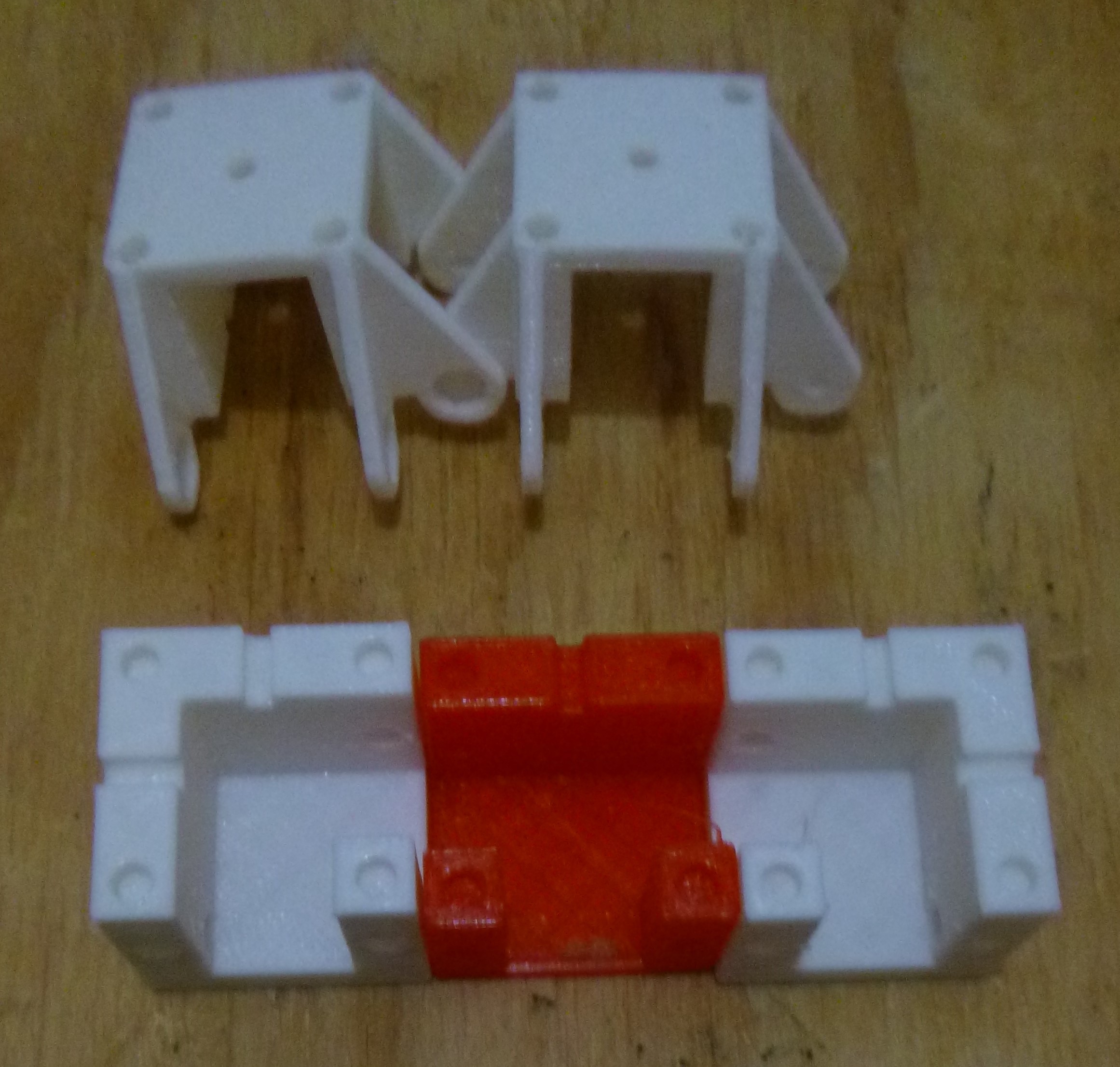
Ran of of red... The white parts will need reprinting with reduced length.
![]()
Again here.........
![]()
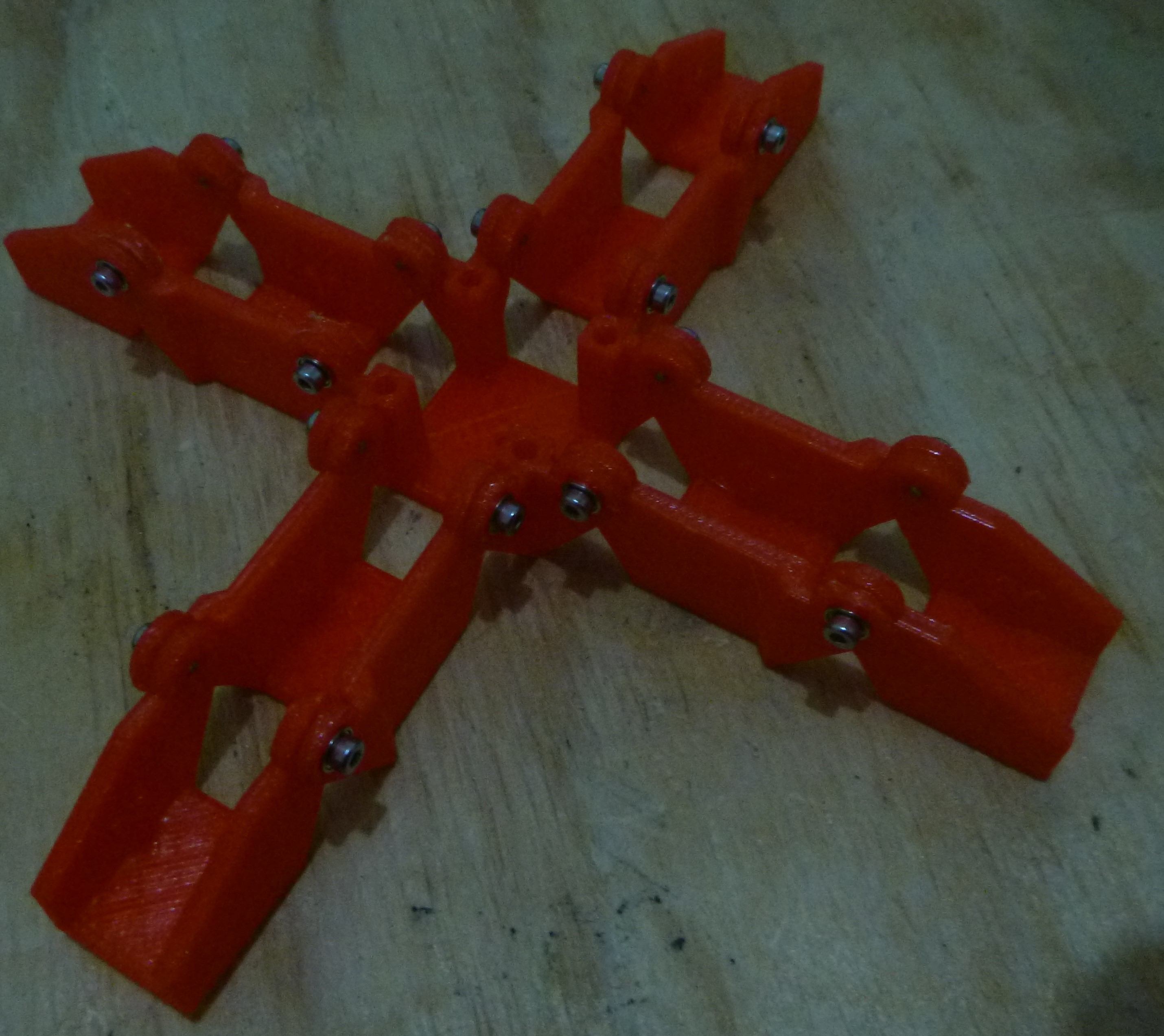
modular concept that will, hopefully, be finish by next week......... maybe.
![]()
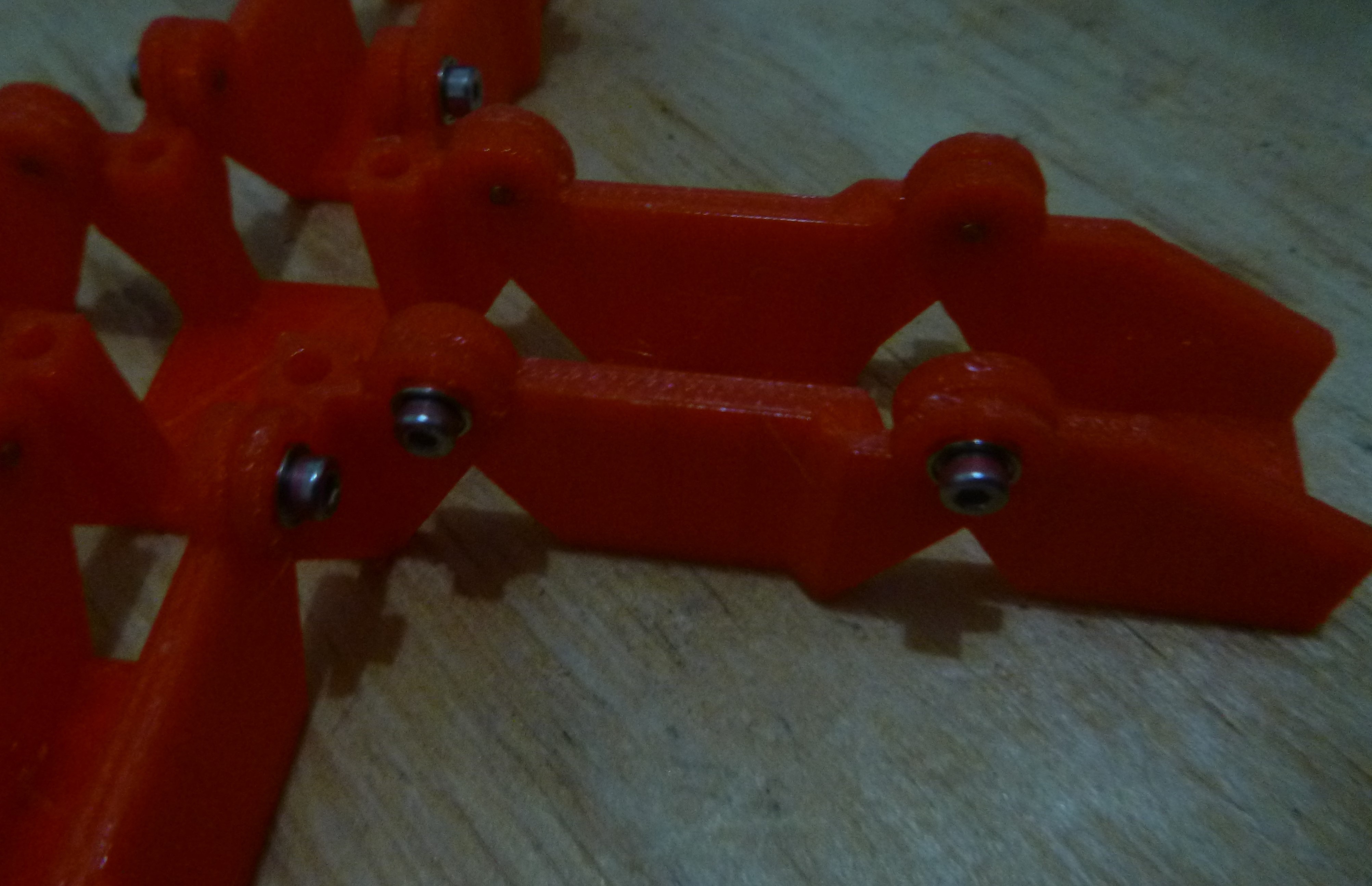
The exoskeleton with the 2mm bolts and bearings. These actually look good, hopefully they perform as well.
![]()
The modularity can be seem here, just removing bolts and changing around the sections to meet the desired gripper requirements.
![]()
-
More mechanical details.
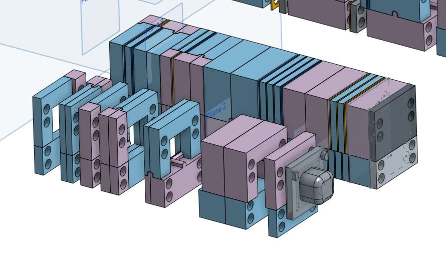
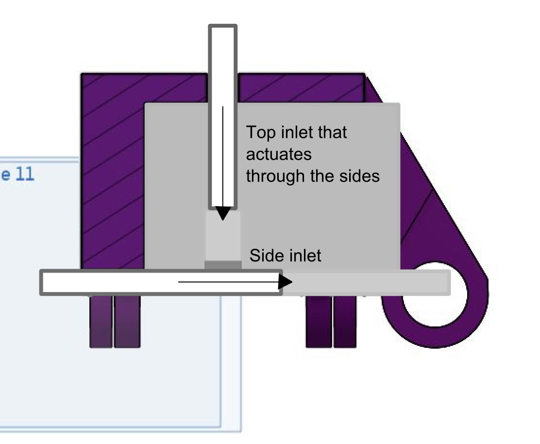
04/21/2018 at 13:57 • 0 commentsThe centre mold section five inlet/outlets, one through the top and four along the bottom. The Top will be only for an inlet whilst the four at the bottom could be either an inlet or outlet depending whether the is an actuator section added. Typically there is only one inlet but, if there is to be a more complex module, like the one below, there would be a need for two in the centre section. The graphic below illustrates two inlets with the lower inlet has the tube extending into the second half of the section sealing the central part and allowing the top inflating the side extensions.
![]()
![]()
Double actuation. -
Actuation driver and Soft locking mechanism.
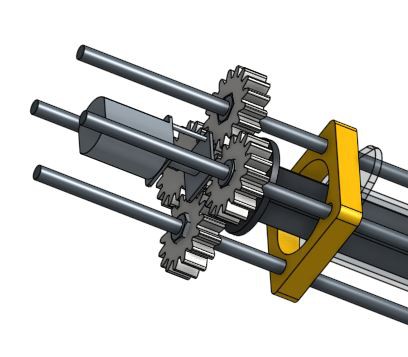
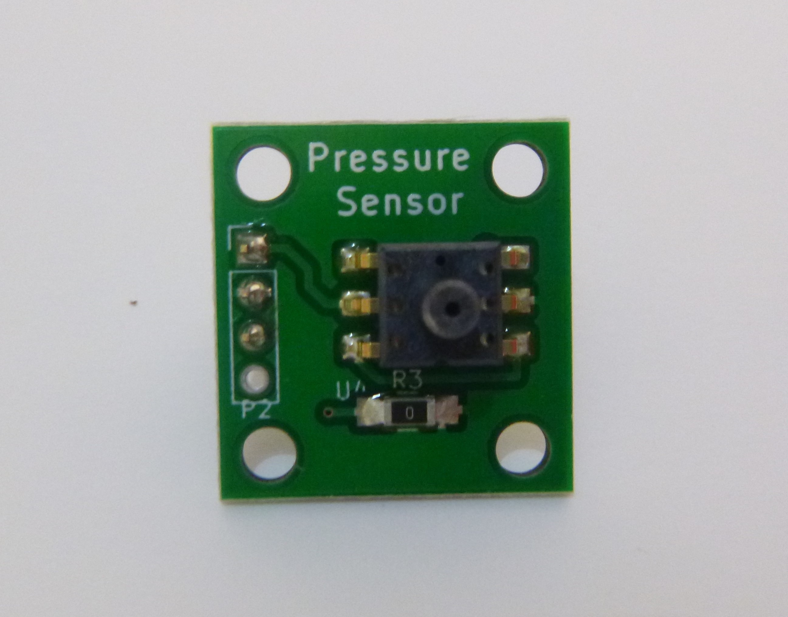
04/21/2018 at 13:44 • 0 commentsAn actuation method for a simple syringe and a geared DC motor that would have an h-bridge driver. The motor is centred between all four threaded rods with a seated nut driving the motor assembly and plunger. Arresting the driving is a pressure sensor that will provide the only feedback for the module.
![]()
![]()
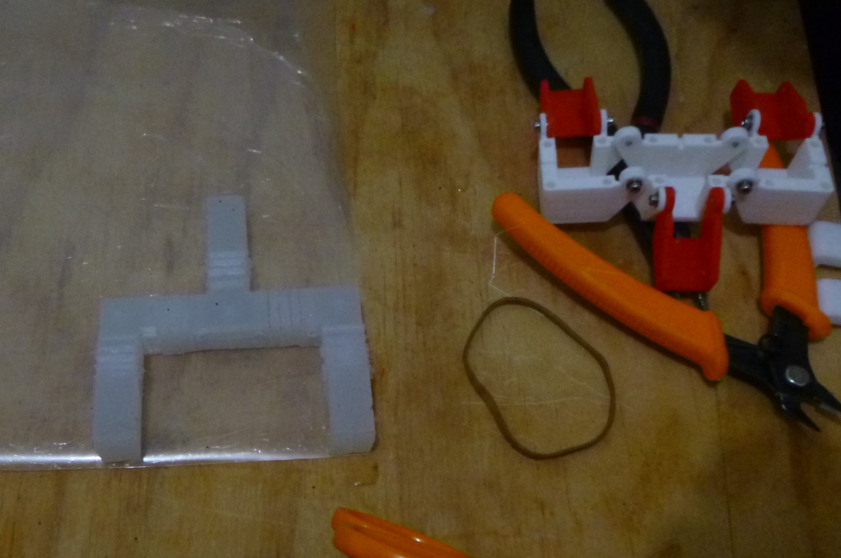
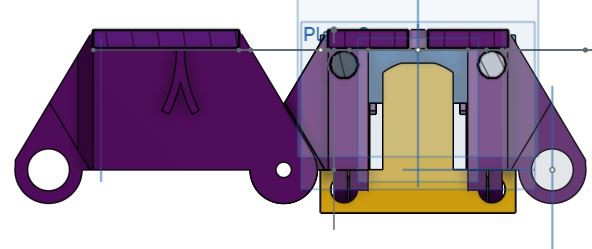
Soft locking mechanism.
The upside down Y is the proposed locking mechanism for the silicone actuator to attach to the exoskeleton. Previously this mechanism was a over hang on the lower edge, which created a problem with the printing. This seems to be a more elegant solution with the negative molded into the silicone.
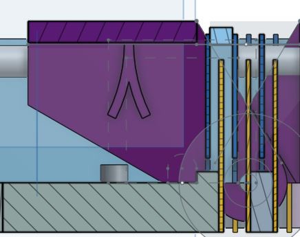
![]()
Section view of the extension section locking mechanism and centre section. ![]()
Sectioned view of end section locking mechanism. -
Modular robot actuation mechanism.
04/18/2018 at 12:47 • 0 commentsAttached to the back of the gripping mechanism will be the pneumatic charging system with a syringe. This seems a possible method with a more volumous syringe being less bulky. The benefit of this method of charging the air is it is the simplest as there is no inlet/outlet values.
![]()
-
Ecoskeleton
04/14/2018 at 07:00 • 0 commentsTo support the silicone actuators an exoskeleton is used so the actuator do the actuation and the exoskeleton provides the structure allowing for more predictable use of the manipulator. Carrying on with the modular theme there is three main sections that makeup the manipulator, the centre, extension and end section. The centre section is the main configurable part of the system that supports the extension and ends.
The pivot is made from small bearing with a inner diameter of 2mm with a mm grub screw acting as the axle fix into the following part be it the extension or end section.
![]()
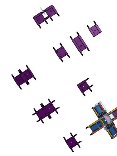
Number of configurations so far. The following is some animations of four possible configurations. With at least seven configurations modeled so far and more possible the number of combinations are extensive. Should do a spread sheet..........
![]()
![]()
![]()
-
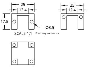
dimensions of possible solution
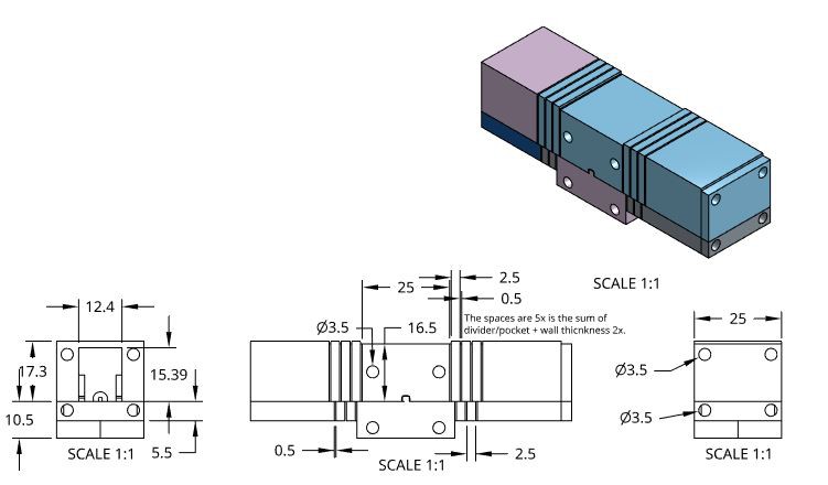
04/07/2018 at 10:49 • 0 commentsDimensions of the centre piece connector. This will be the keystone of the design as this will be the part connected to the air supply.
![]()
![]()
![]()
The pockets and dividers for the actuation is designed for use across any actuator.
![]()
-
CAD prototyping on modular structure.
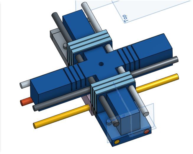
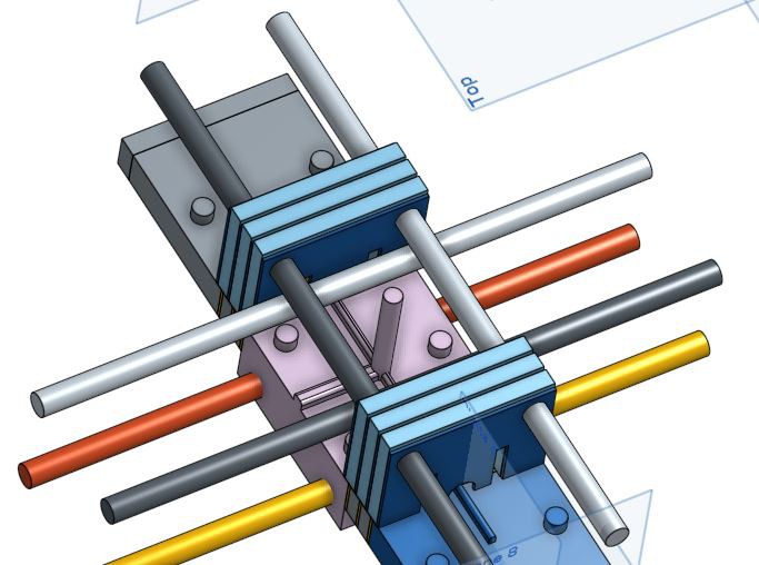
04/06/2018 at 13:09 • 0 commentsThe idea is to make these fabrication blocks as modular as possible. CADing these is a good way to take good ideas and turn them into bad ideas. The method of binding the sections together with M3 threaded rod works for the linear sections that follow one after the other. A problem arises when joining at right angle, or at any angle, as the rods cannot now be in the same plane. The top section works as there is plenty of meat and they can be moved down, was thinking about doing that anyway as that would reduce the torque in the mold. But, at the bottom extra 5mm needs to be added which might no be to bad....... maybe.
![]()
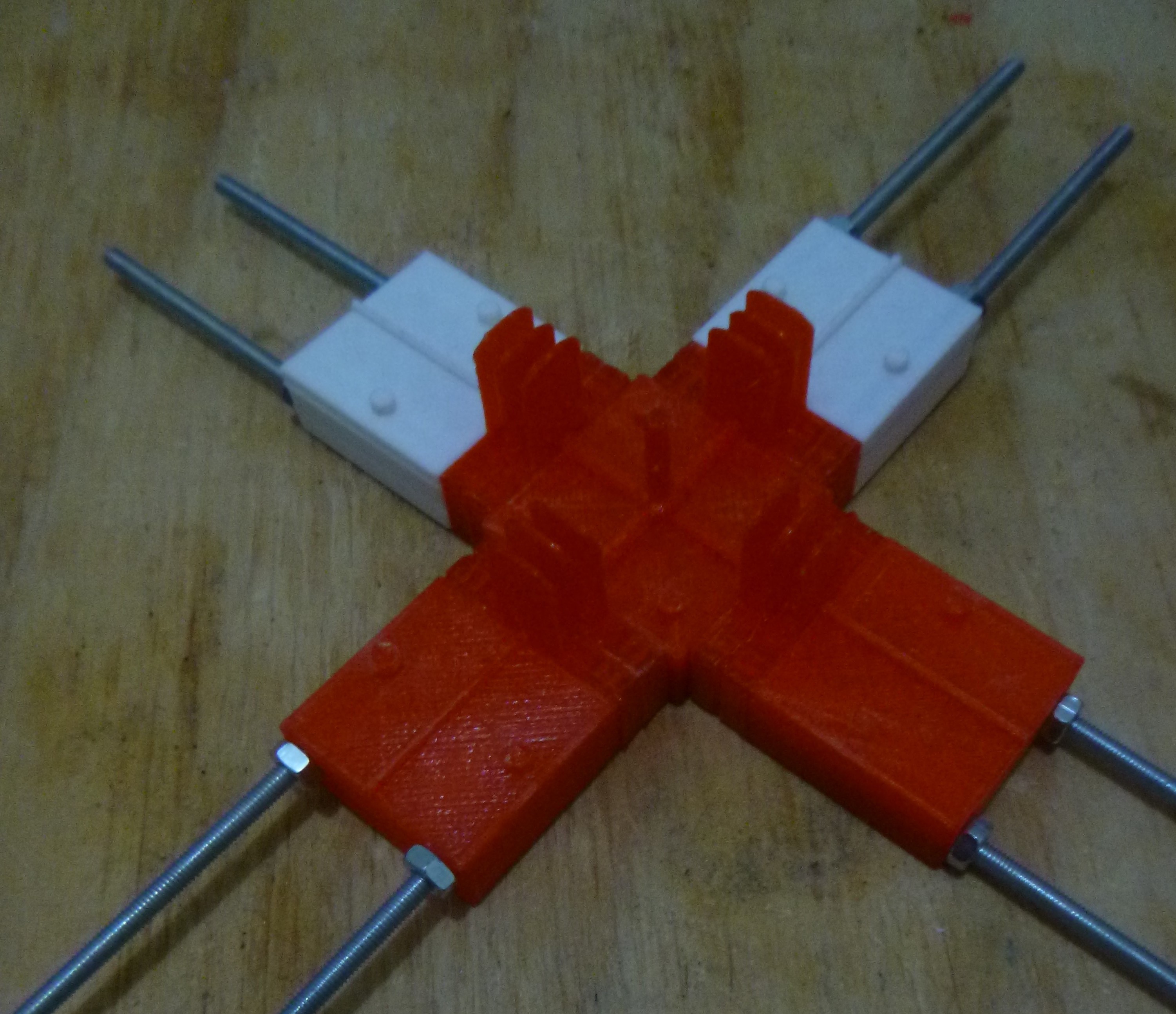
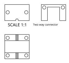
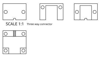
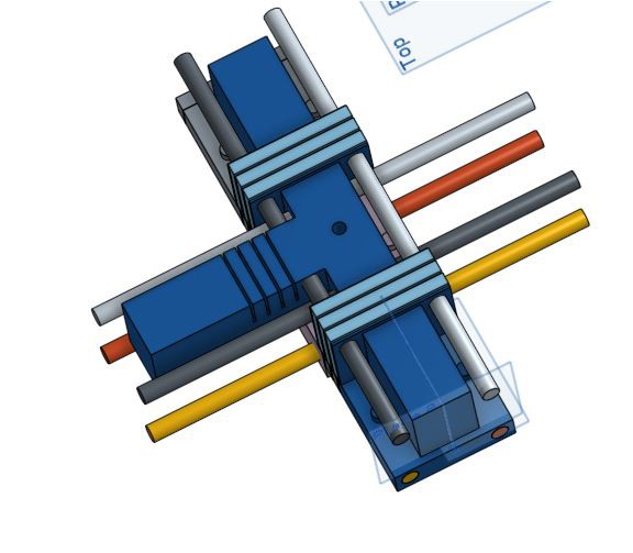
Four way junction with air inlet through the top. ![]()
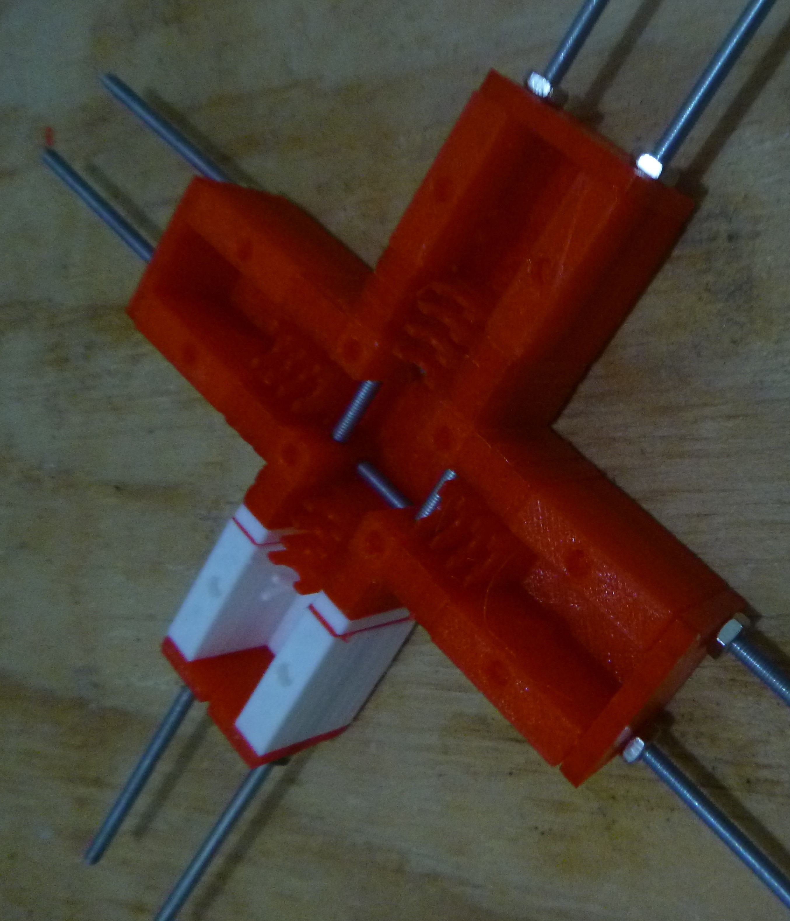
Three way junction ![]()
mmmmmm is this the problem or the solution Thinking thinking thunck
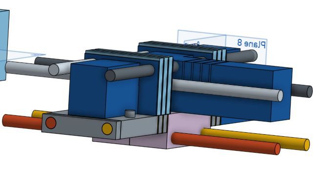
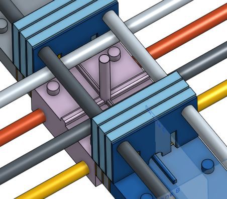
There clearly is going to be an increase in complexity of the molds, but with the above mold this is not a problem. The only major change is with the bottom mold pieces as the above pieces just have two extra holes in an area with plenty of plastic.
![]()
Centre piece of the mold Probably the piece that will contain the most complexity is the centre piece that all other sections will attach and the air inlet will be. The more I think about this section the more I think this is the right solution. Normally the air hose is attached to the back, but if there is going to be a section on it then that will be blocked.
![]()
But this.......... As a generic section the one with all sides open would only need the holes sealed, easier than attaching the flexure.