-
1You can download Instrucitons "BuildInstruction4.pdf" (1.7 MBytes) from the Files here
You can download also Instrucitons "BuildInstruction4.pdf" from the repositary Build Instruction v.4
-
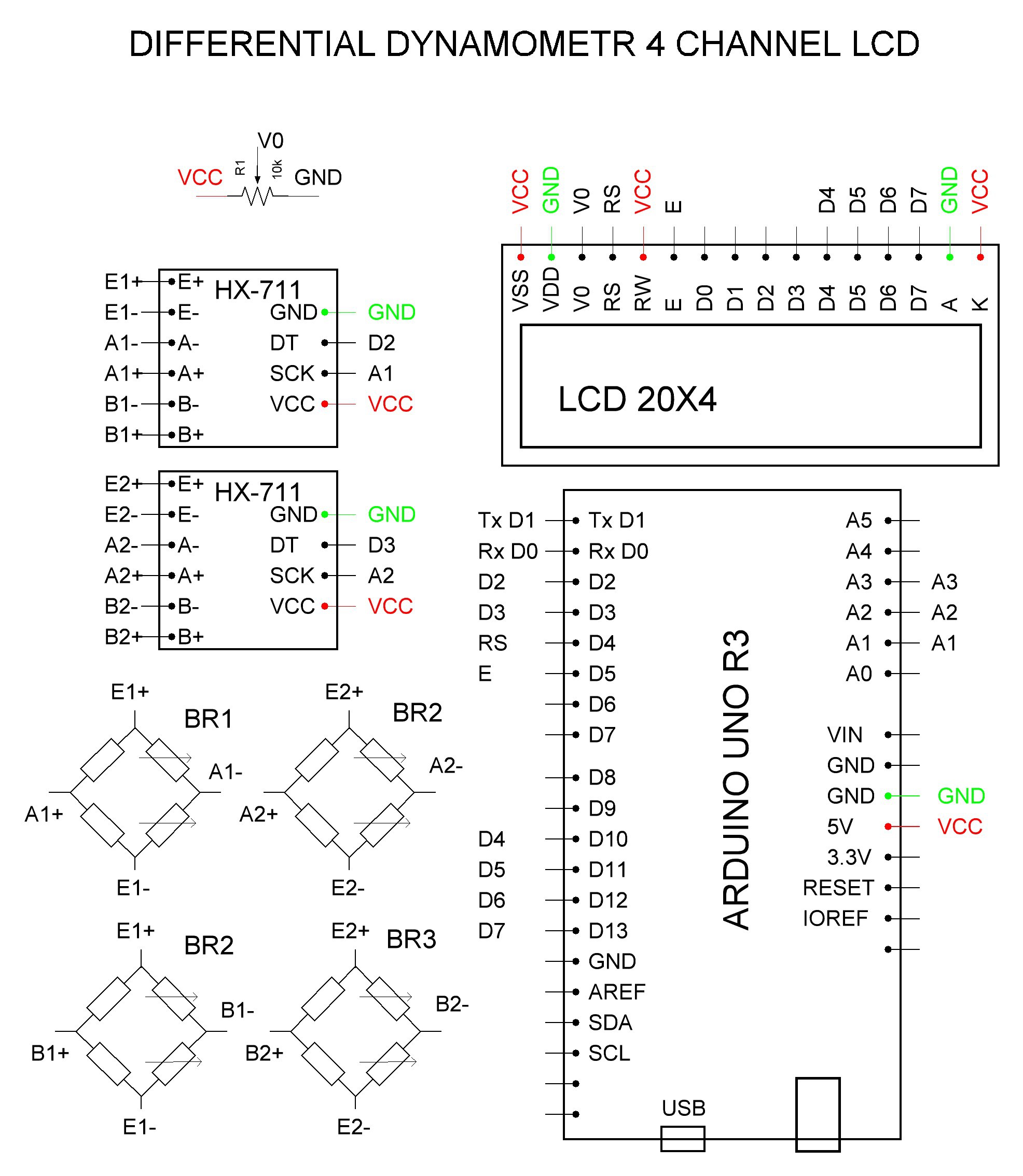
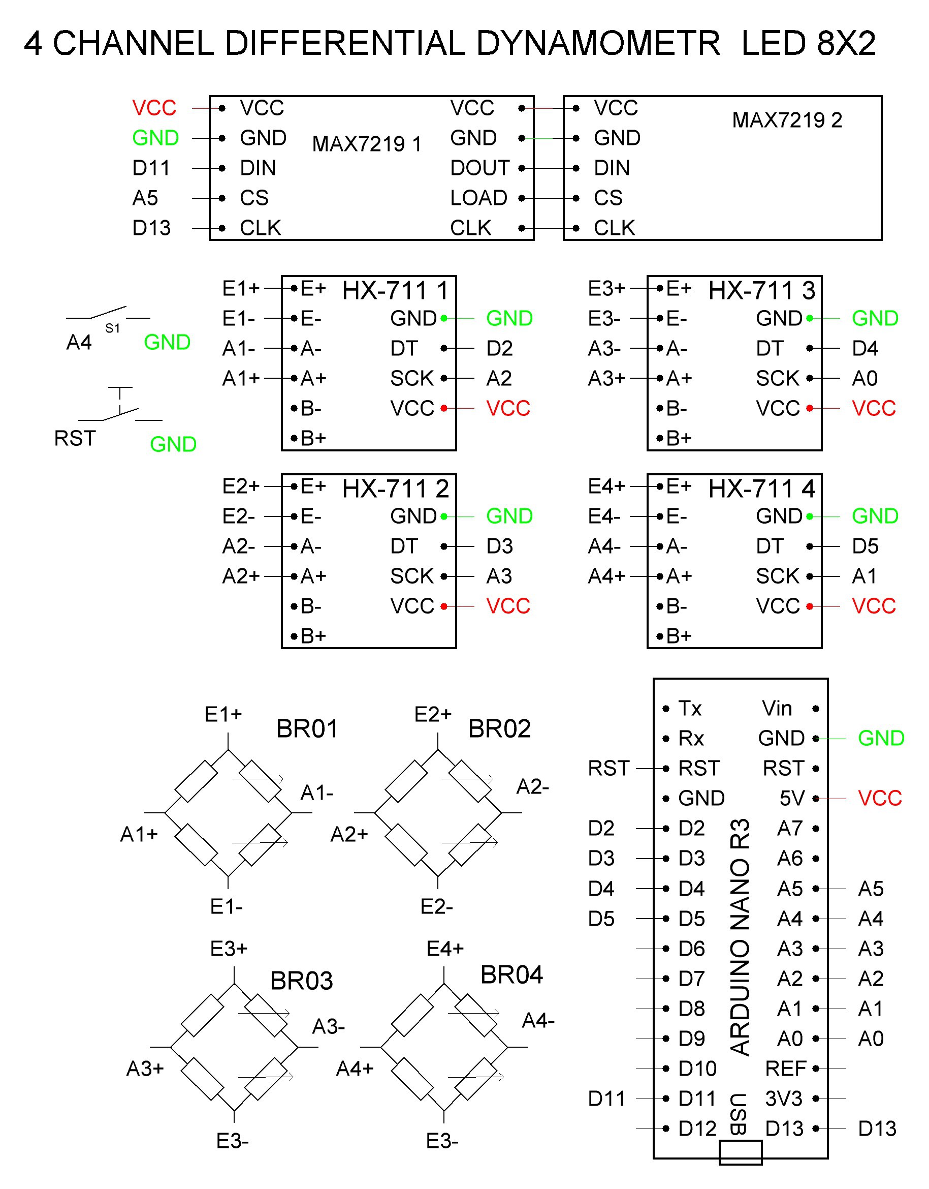
2You can see the main stages of construcion here. Schematics.
We construct two versions of the devise. The firsto version include LCD and here is schematics
Here is schematics of the device with LED Display. We pay attention to this version becouse LED Display is more usable. You can consruct the device with LCD Display the same way. The only difference is size and situation of Display.
-
3Housing
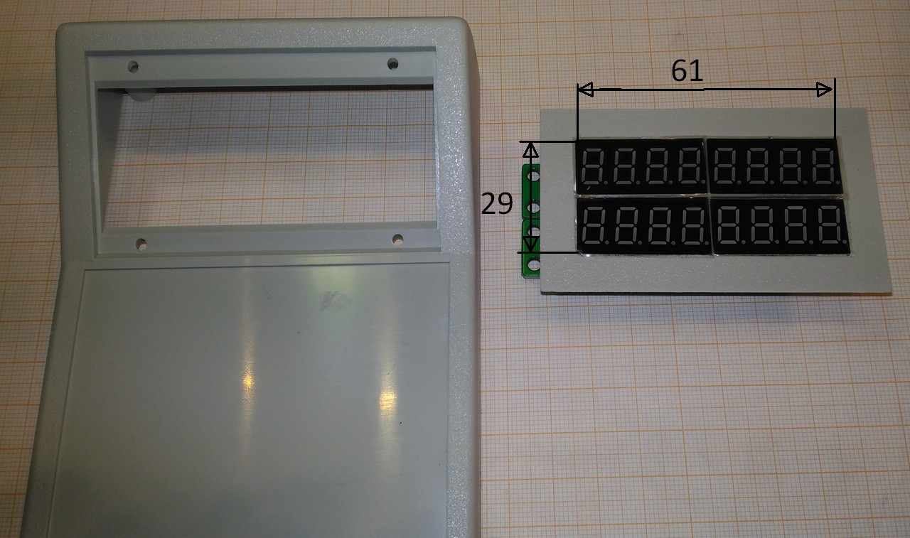
We use ready box (housing) G1168G Gainta. You only need to make a slot for the LED or LCD display.
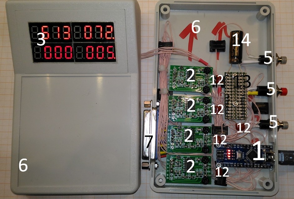
![]() Assembled devise is shown here, with
Assembled devise is shown here, with - 1 Controller
- 2 24 bit ADC shields
- 3 8 digits LED shields
- 5 Push button
- 6 Box for device
- 7 DB25F connector
- 12 0.1 uF 16 V capacitors
- 13 PCB for GND and VCC connections
- 14 3300 uF 16 V low ESR capacitor
![]()
-
4Sensor board
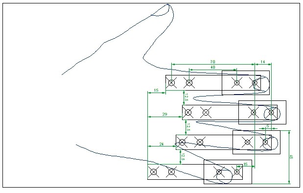
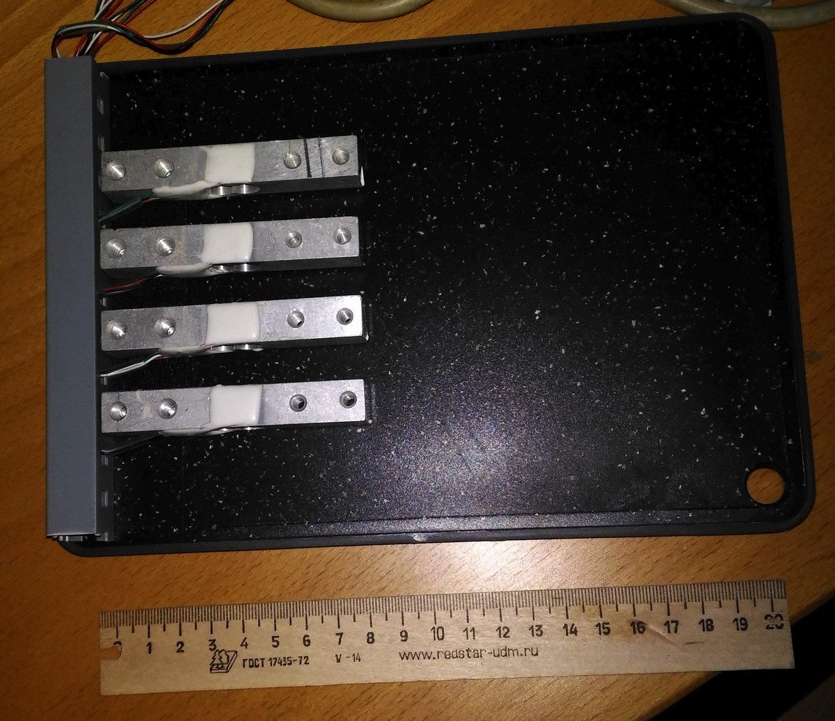
The sensor board can be made from plastic breadboard or tray. You need only drill. Here are samples on a breadboard and pllywood.
![]()
![]()
-
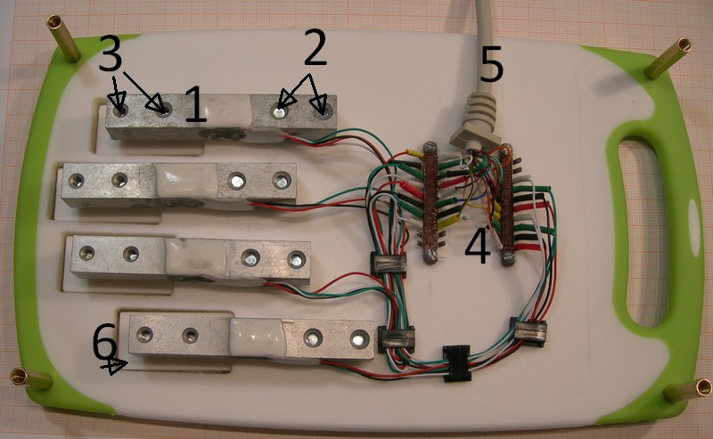
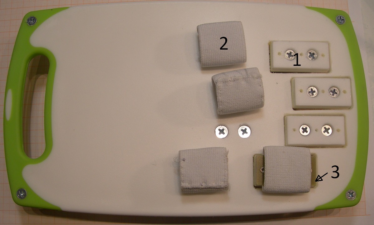
5Sample of a sandwich plastic breadboard sensor board
Four sensors (1) are attached with screws 2 with washers to the plate, and four finger plates (6) are attached to the sensors with screws 3. All wires are soldered to the terminals 4. Cable 5 goes to device. The bottom plate is screwed to the four screw racks.
![]()
![]()
![]()
Dynamometer for Post Stroke Rehabilitation
An open-source, 4-channel differential dynamometer for post-stroke rehabilitation. Includes 4 force sensors, device with display and PC soft
 Sergei V. Bogdanov
 Assembled devise is shown here, with

Discussions
Become a Hackaday.io Member
Create an account to leave a comment. Already have an account? Log In.
Instruction for LED Display device
Are you sure? yes | no