Marius Taciuc
-
Spice simulation of the Buck converter
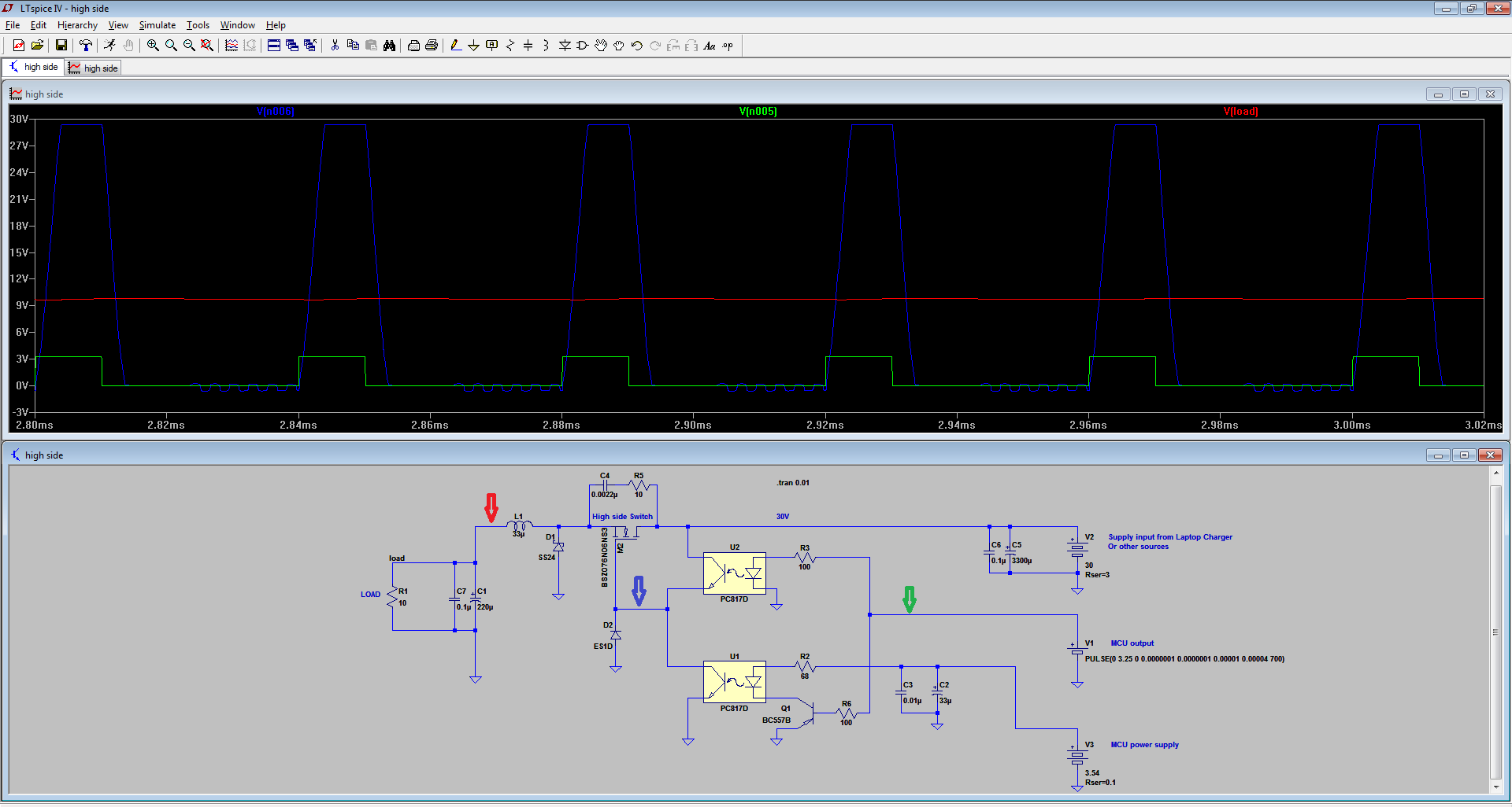
08/01/2017 at 01:24 • 0 commentsI'm posting today an LTspice simulation of the buck converter. I went for the simulation because it is always a better way than to try to change physical values of the components and try to remake the tests and measurements.
I might go for this variant of the Buck module, so I must integrate it into the larger schematic. Don't mind the actual value of the mosfet. I just used whatever I could find in the list that matched the characteristics of the IRF3205 (the one I'm planing to use). The simulation showed that I obtain better results with a 33uH inductor. It also reveals that increasing the current through the optocoupler LEDs I can obtain stiffer slopes. The simulation measures a maximum slope of around 2.5us instead of up to 10us per rising slope in the A2 iteration of the schematic. Much better!
I think this optocoupler approach in trying to build a mosfet driver for a high side switch is not the fastest one, but it surely is a cheap and reliable one. The D model of the 817s is the fastest one and it seems like with this schematic, the on-off switching times are just enough to make the optocoupler transistors NOT open in the same time.
I would call this the A3 iteration of the schematic after I integrate this module into the large schematic.
I ran the simulation at a PWM frequency of 25KHz, just above the audio band. A drawback of this actual design is that I cannot go higher because of these slopes.
At this point of the design, I'm wondering about the efficiency of the entire schematic.
Stand by for updates.
-
Creating software custom chars
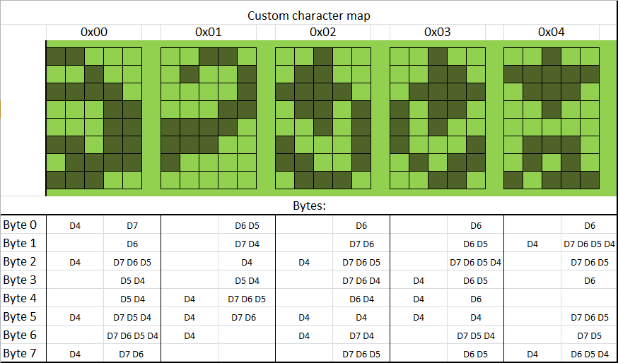
07/31/2017 at 04:36 • 0 commentsI already uploaded a chart with some custom chars I wanted to create for my LCD display.
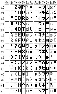
The LCD itself has only these ones defined in it's internal map:
For those who do not know and never had the opportunity to play with these displays, the first column is the CGRAM column and it can be populated with whatever char you need. I drew them like in the following picture, sending the respective bits to the display. if you noticed from the schematic, I only used 4 bit LCD communication.
![]()
The first two custom chars, represent the Scorpion logo that will be used after initializing the display and in some sub-menus. The 3rd one, that I located in the 02 location of the CGRAM, is the rotate left character. Then follows the Rotate Right, and push down ones.
If you follow this post, stay in touch for some other updates. I hope I'm gonna publish very soon a temporary software iteration.
-
Test circuit
07/31/2017 at 00:38 • 0 commentsI used an MSP430 launchpad and I built the circuit using some wires as you can see in the video below.
I decided to use IRF3205 as my switching mosfet, because it has the proper voltage ratings and it also has a very low RDSon. For the coil value, I used a 22uH. I'm planning to test different values up to 33uH at different frequencies.
The major problem with this schematic is the rising slope as you can see in the video above. The oscilloscope measured sometimes more than 5us because of the gate being connected to the drain through that resistor. Lowering the value of the resistor will definitely decrease the rising time, but I cannot connect a lower value between + and - or it will simply burn when the gate transistor is opened. And it seems like the opening time of the mosfet is dependent on the voltage difference applied on the gate and the value of this resistor through which the gate capacitance eventually charges. Since my gate is opening at the drain voltage and I cannot lower the value of the resistor, I have a real problem.
Not very content about the fact that I'm loosing so much thermal disipated energy on that slope.
I made some short efficiency measurement and in some cases is around 50%.
I definitely have to look for a half bridge or a mosfet driver at this point.
Another problem is the minimum input voltage for the entire schematic. I must definitely have at least 4.5V for my logical circuit and for my LM317, but it seems like in some cases, I have to have more than 6V to be able to open the mosfet.
Other than this. it looks like a cute design.
More updates coming in about the software and the custom alphanumeric chars you see on the screen.
-
Schematic upload
07/28/2017 at 01:53 • 0 comments28/Jul/2017
Uploaded firs functional iteration of the schematic. The working principle is not so complicated. I just hope I manage the software design right.
Another concern that strikes me is the switching times of the buck mosfet. In my case it is basically a high side switch. Usually, is not so simple to control high side mosfets with a low voltage source. My MCU output pins are only providing like 3.2V or something. My mosfet is definitely switching on and off right now, but at what rates and what frequency, this remains to be simulated and tested.
-
Block diagram
07/27/2017 at 00:07 • 0 comments27/Jul/2017
Added the block diagram and better defined the concept.
More files coming soon.
-
Getting started
07/26/2017 at 06:09 • 0 comments26/Jul/2017
I managed to upload a small sketch of the design, a brief description and a short explanation of the idea of the design. More pictures to come and a temporary schematic of the design.