Nigel
Nigel-
Delaaaaaaysssss
02/09/2015 at 04:09 • 1 commentSorry for the lack of updates. I ended up getting an internship at Tesla so work has been keeping me really busy and my car and equipment are currently 2k KM's away which also makes things difficult. I've made a few more changes to the circuit and it's now more closely based on a standard comparator instead of an inverting amp. Will have those LTSpice images up soonish and also should hopefully be adding some updated C code to the git shortly.
-
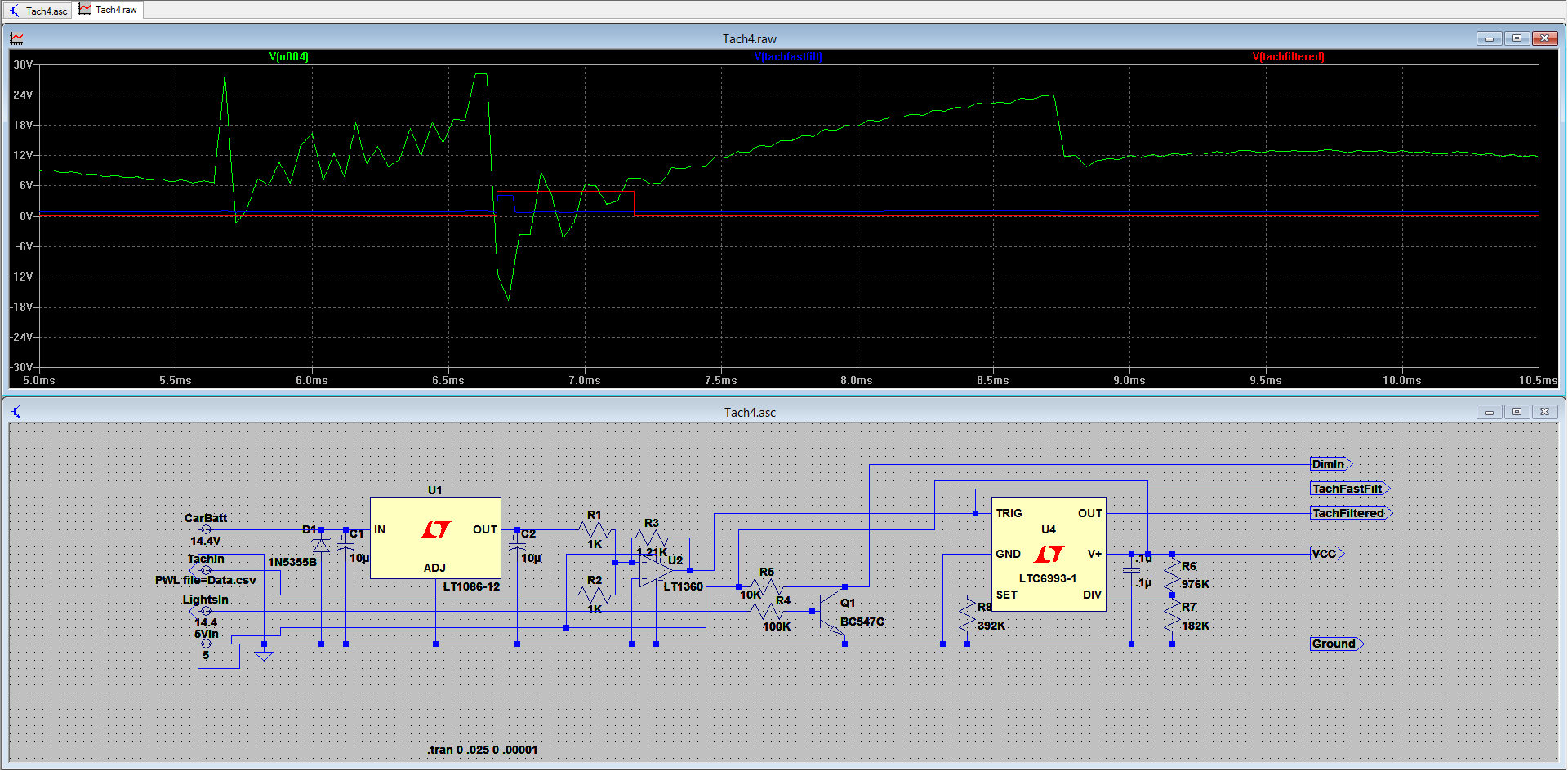
Completed System Design
11/07/2014 at 22:00 • 0 commentsI think I've now completed the system design. The vibrator IC might not be completely required but will help with stability/sensitivity. This new SPICE sim also includes the cluster light input.
![]()
-
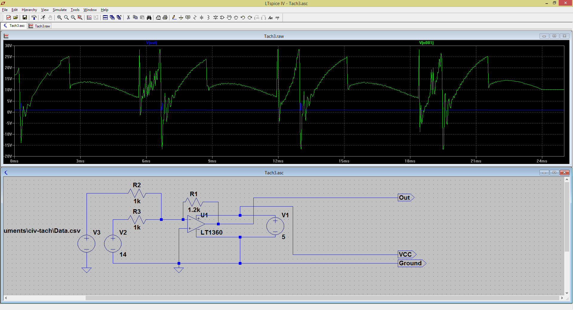
New Filter Design
11/03/2014 at 05:44 • 0 commentsI've found a new, and hopefully more reliable and robust method of filtering the input signal from the tach. It uses an op amp in an inverting summing amplifier configuration. Next step is to order parts and breadboard it. Thanks for reading!
![]()
-
Call for help!
11/03/2014 at 03:36 • 0 commentsI'm working on a 2nd method of filtering the tach input signal. My next idea is trying to use the negative pulse to trigger a mono-stable vibrator to give some control over the pulse width. I'm working on isolating the negative pulse that falls below -10V or so but I'm struggling to come up with something that works. Anyone have any suggestions for possible methods of doing this?
EDIT: Is using a summing amplifier (other voltage source being VBATT) to shift the wave up followed by blocking all the positive components to isolate that negative components we want ok? It should work, but are there any alternatives that would be better?
EDIT2: Using an op amp in an inverting summing amp? It would eliminate the need for the extra blocking step and conveniently inverting the good signal for us. Putting it into sim now.
-
Video!
08/21/2014 at 04:18 • 0 commentsThe video is done! Check it out here:
-
Code Overview
08/21/2014 at 04:13 • 0 commentsI'll go over the code in chunks. Instead of pasting it here, please open up the bitbucket repo or the .ino file in an IDE and follow along with the line numbers.
Lines 1-30: Basic declarations and includes nothing special here.
Lines 32-89: This is our initialization step. We start up software serial (using this because of how often I'm updating the firmware. I want to keep the HW serial free for now. It then runs through the little start up routine so you can check for any issues with the display. After than it latches the interrupt to wait for the first pulse of the car to begin measurements.
Lines 91-98: Main loop. Super simple, just keep looping and if more than .1 seconds have passed since the last screen update, update the screen.
Lines 100-106: Fresh start routine. Pretty much resets the timing so that the very first measurement is accurate and doesn't take in a ridiculously long value.
Lines 108-121: Stores the time between pulses in an array. It rolls through the 5 locations in the array to gives us our values that we then average.
Lines 121-173: This is the anti-jitter code. I found this on the Arduino forums years ago and haven't been able to find the original thread to give credit to. It takes in the to be displayed value and a threshold and determines if the value is ok to display. It looks for either two consecutive values trending in the same direction or the gap between two values is larger than the specified threshold.
Lines 174-187: The code that does the actual writing. Since the display expects 4 digits per send we must send a null character if the number is less than 1000.
Lines 189-233: This is the function that actually calculates the RPM to update. First it checks to see if it is in the correct state for display dim. Then it calculates the RPM from the stored pulse times. Following this is it checks to see if it needs to turn on any of the LED's , as well as if it needs to display the car is off. Finally it sends the RPM value to be printed on screen and the process starts over again.
-
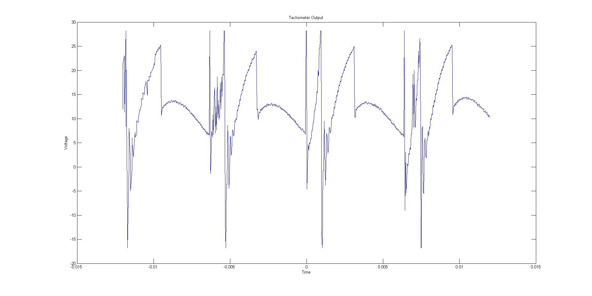
The Filter
08/19/2014 at 20:07 • 0 commentsThe filter is probably the trickiest part of this project for me. This was my first time using LTSpice and overall I'm happy with the results. I was able to create a working filter in the program and then breadboard (and then perfboard) a working filter from the design.
The input waveform:
I've unfortunately deleted the original waveform files I had saved from my Rigol 1052E but I'll remake them as soon as I can. (EDIT: Added pics) The basics of the waveform was that it was a +-20Vish super noisy pulsing waveform. The main challenge I faced was making this into something the Arduino can read while still preserving the data integrity. Simulation tools were used in order to achieve this.
![]()
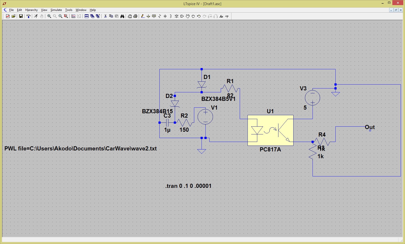
The Filter:
![]()
This is the current revision of the filter. It takes the waveform in from the car and converts it into a 5V square wave. The intention of the first RC stage is to reduce some of the noise coming from the input. After this, the two Zeners are for first truncating the waveform to remove any false positives and then cut off the voltage at 5.1V to protect the opto-isolator from any spikes in voltage.
-
To Do:
08/19/2014 at 19:47 • 0 commentsFirst log update, figured the To-Do section would be a good place to start.
Contest Specific:
1) Get pictures up. Done
2) Finish Logs. Done
3) Get video up.Done
4) Clean up project page. Done
Overall:
1) Sort out Git for the software. DONE
2) Refine current hardware design.
3) Design new single PCB layout with new hardware. Get it made.
4) Port over and clean up code to C.
5) Design new case and get it printed.
6) Assemble, and chill.
Honda OBD1 Digital Tachometer
In this project I'm building a digital tachometer for 90's Hondas.