The final module to test of the network analyzer is the four channel demodulator.
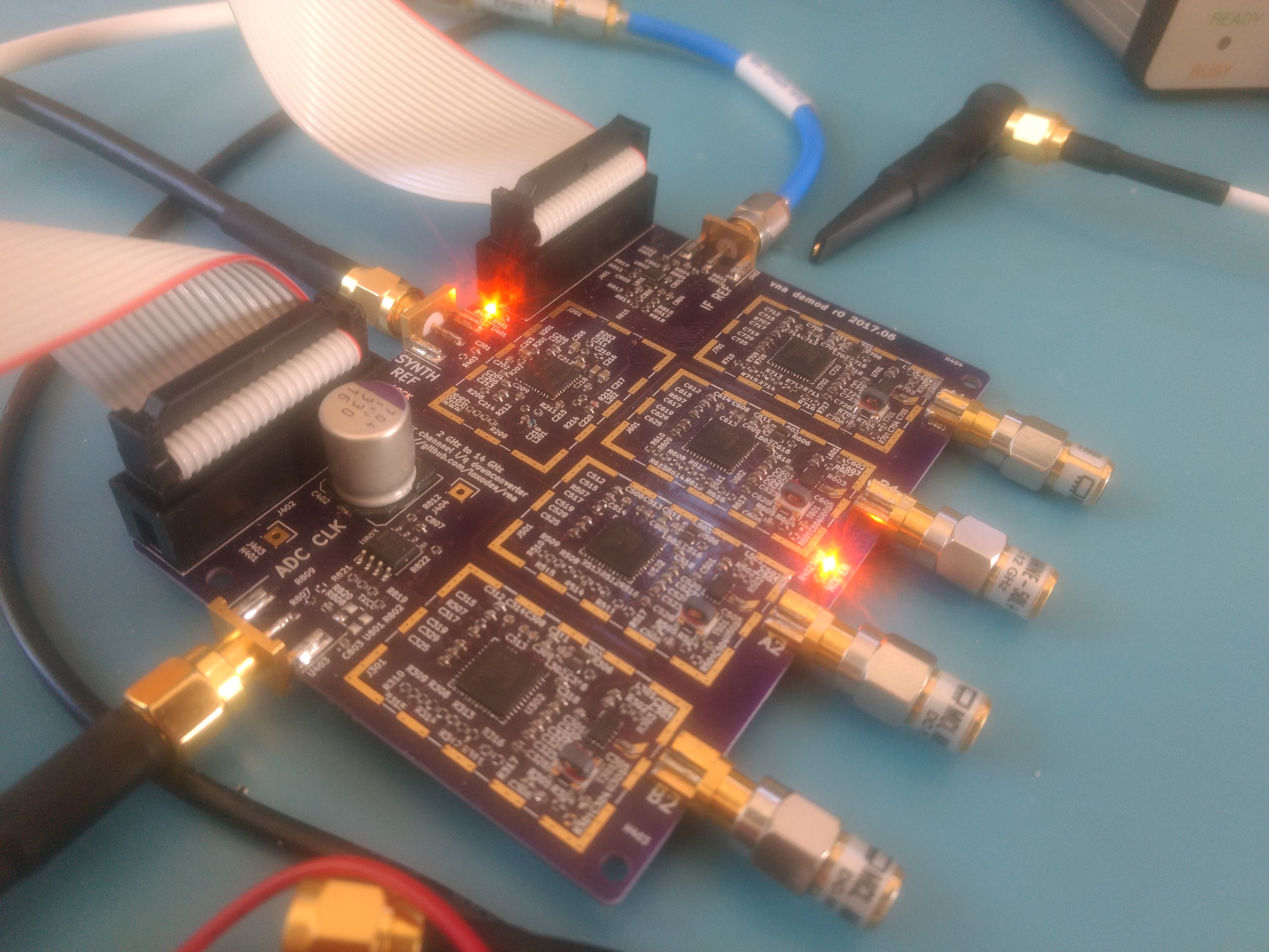
This board mixes down four microwave channels to a 48.25 MHz IF frequency then simultaneously samples them.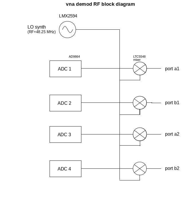
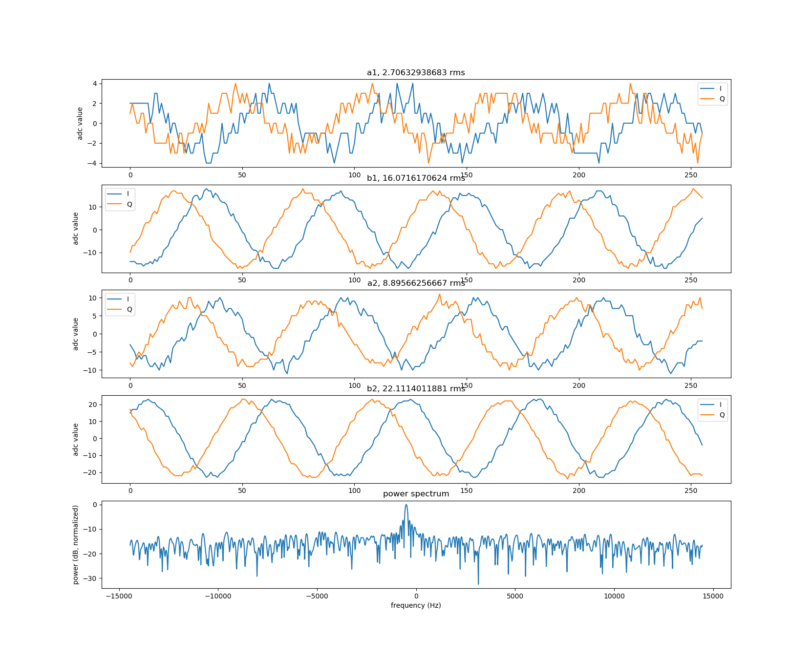
Other than a bad solder joint on one of the mixers, bring-up on this module was uneventful. However, I uncovered leakage problems with the RF synthesizer board while testing this board. There is still a signal at the ADCs even when the synthesizer outputs and demodulator inputs are terminated - to the extent where |S21| and |S12| approaches -50 dB by 13 GHz with both ports terminated. To illustrate this, here are raw samples off the demodulator at 13 GHz:
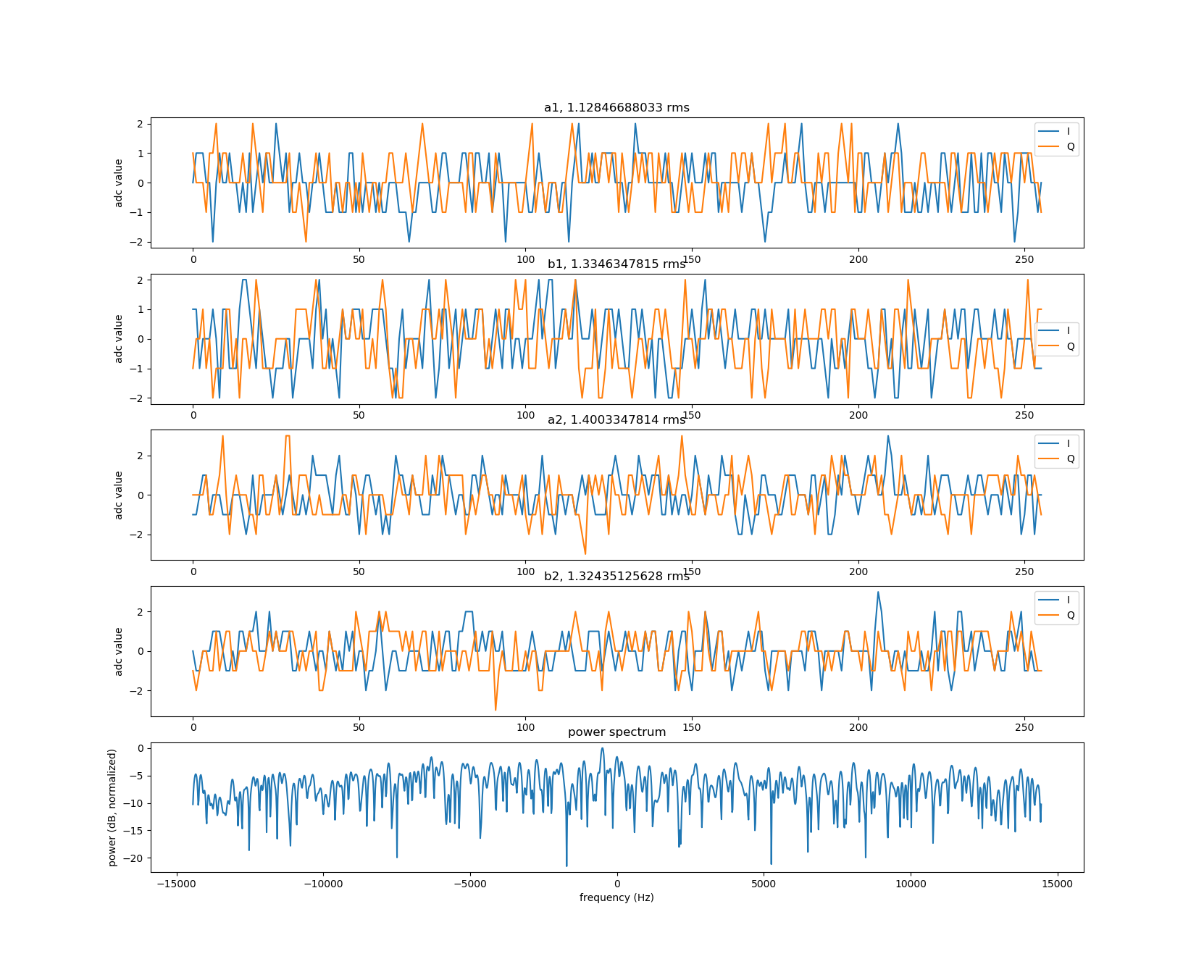
And here are samples at 2 GHz showing little coupled signal:
This signal goes away when the synthesizer is powered off, so I suspect this is a problem with the synthesizer signal coupling into the demodulator board. Populating the shields on the synthesizer board didn't improve isolation much so I suspect this is at least partly due to conducted emissions through the data/power cable.
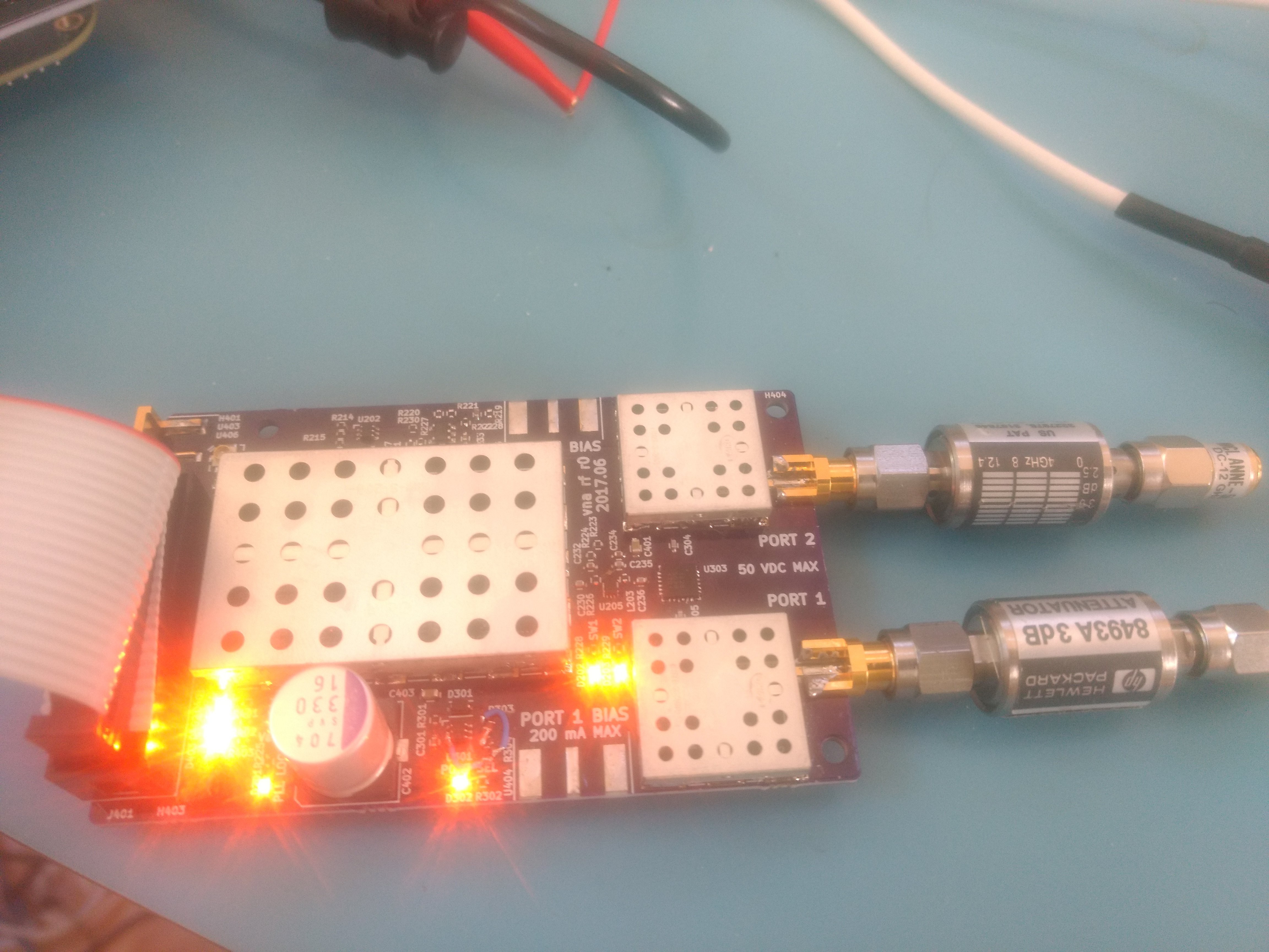
Decoupling the data lines off the synthesizer board that had easy access to ground with 10 pF capacitors improved isolation by about 6 dB. I'll need to be more creative to find a way to bodge on capacitors for the remaining data lines..
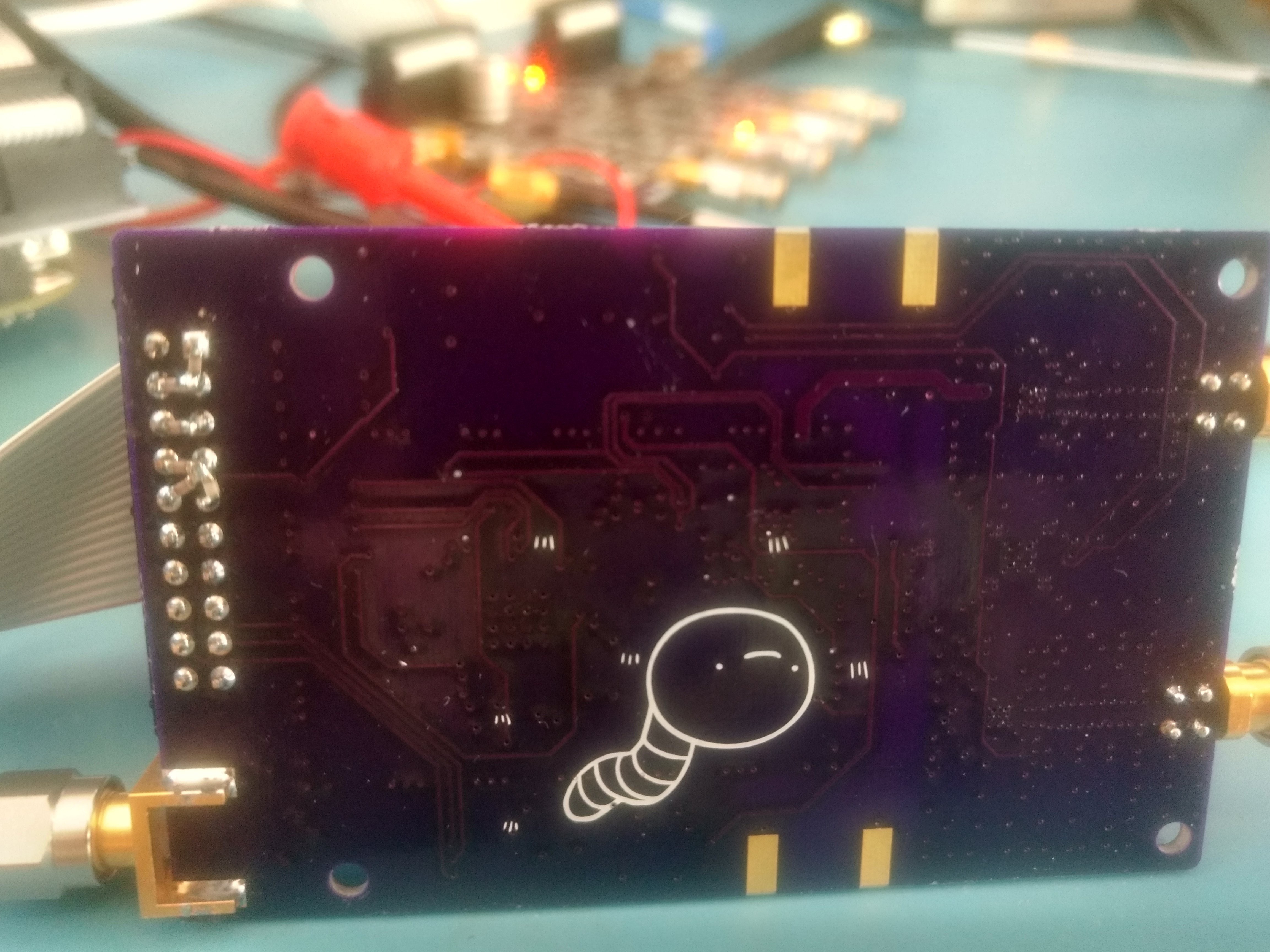
Even with the isolation issues, the VNA produces plausible looking measurements. The measurements have more ripple than with the previous iteration of my VNA. I suspect this is at least partly due to inadequate calibration standards. Earlier I was defining my calibration standards from measurements taken with an Agilent E5701C calibrated with a 9 GHz ecal. Since those measurements only went up to 9 GHz, now I'm assuming the open, short, and load have ideal reflection coefficients after some electrical length. I need to look at the E5701C measurements of my calibration kit and see if I can extrapolate a better approximation of the standards.
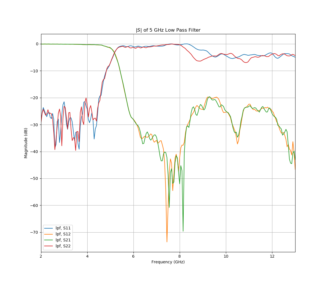
Here is a 5 GHz stepped impedance low pass filter:
Phase measurements on a SMA barrel look plausible:
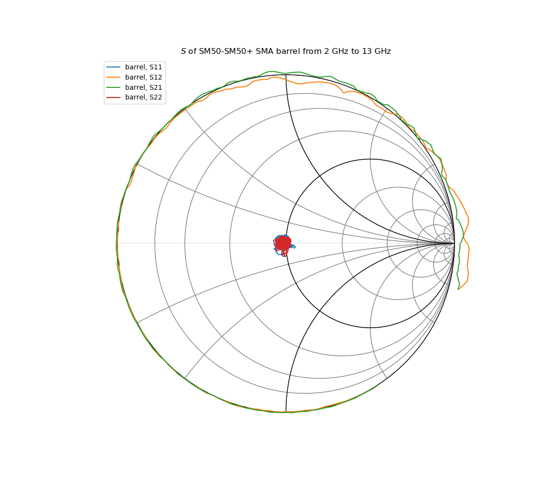
There is some probably non-physical ripple in the return loss. I suspect at least some of this is from reflections into the demodulator board. I ordered some used 3 dB attenuators off eBay to try out ... resistive matching, maybe they will improve measurements a little.
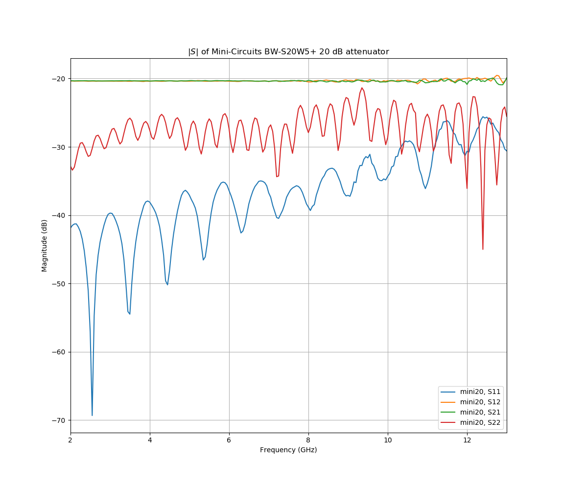
The network analyzer produces reasonable looking measurements, but I still have work to do on improving calibration and isolation.
 Jon Klein
Discussions
Become a Hackaday.io Member
Create an account to leave a comment. Already have an account? Log In.