I didn't like the way the ART56 gears are mounted. So I decided to redesign it. Below the renderings of this new design
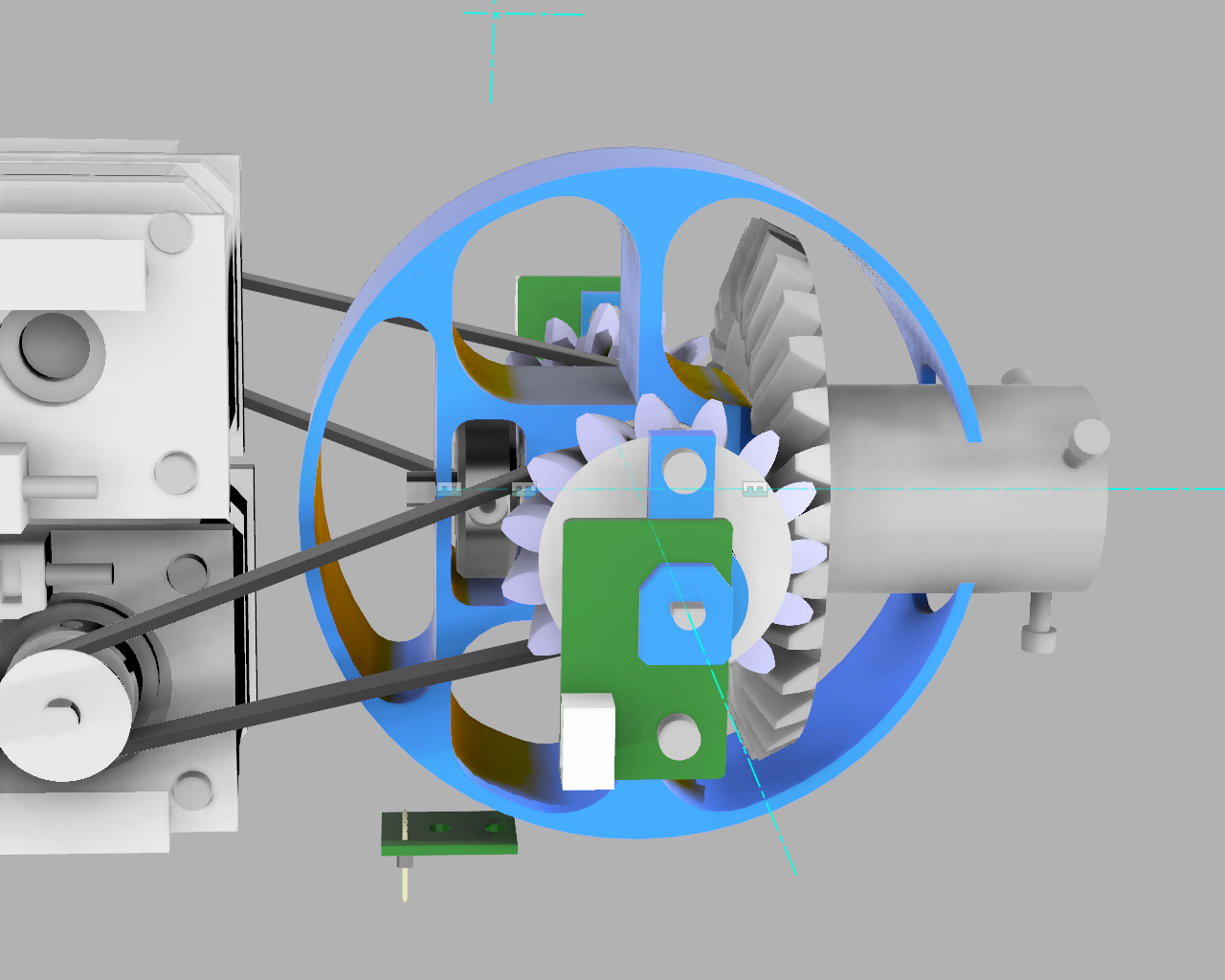

Below on the bottom the old version. There is just a few mm to mount the screw which forms Axle 6. In the new version a real axle is used and it is guided by two bearings. There is also room for one or 2 rotation sensors on Axle 6.
Also the bearings of Axle 5 are removed. I splitted this axle into 2 parts. The axles can be "screwed" into placed by placing them into a electrical screwdriver. They are fixed inside the new part so the rotation sensor will work.
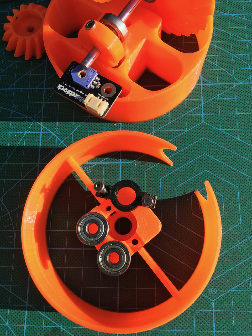
First put a bearing on the top side. (You can reuse the old bearings).

Then put the other bearing on the bottom side.
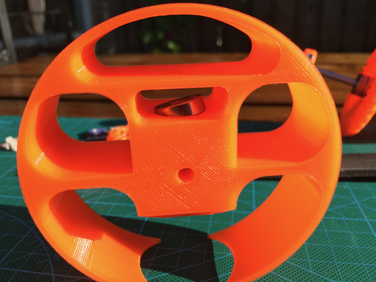
Use a flat tool to push the bearing in it's hole.
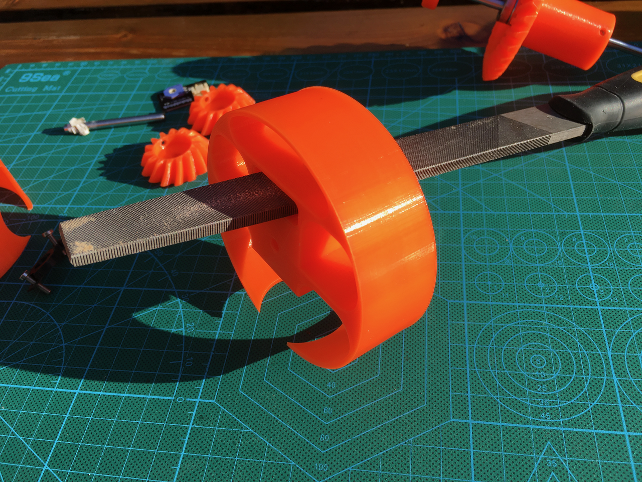
The axle will be mounted like this. From right to left.
- The big gear
- 2 M5 spacers
- A bearing on the top side
- A bearing on the bottom side
- Another M5 spacer.
- The Axle6Fixer that prevents the axle from moving up or down.
- (If there is room another 5MM spacer. I didn't use one)
- One or two rotation sensors.

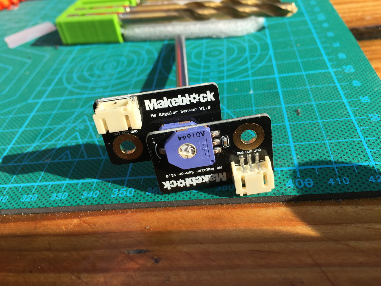
The makerblock rotation sensor doesn't support a full 360 degrees rotation. If you mount 2 of them on the same Axle then it will be possible to measure all directions.
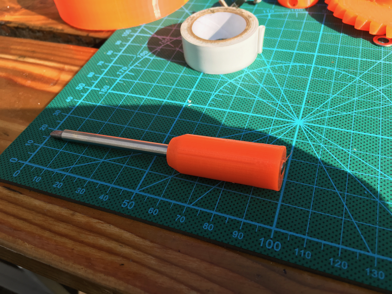
Use a electrical screw driver to screw the Art56GearPlateAxleHolder_01 on the axle. It will be a tight fit.
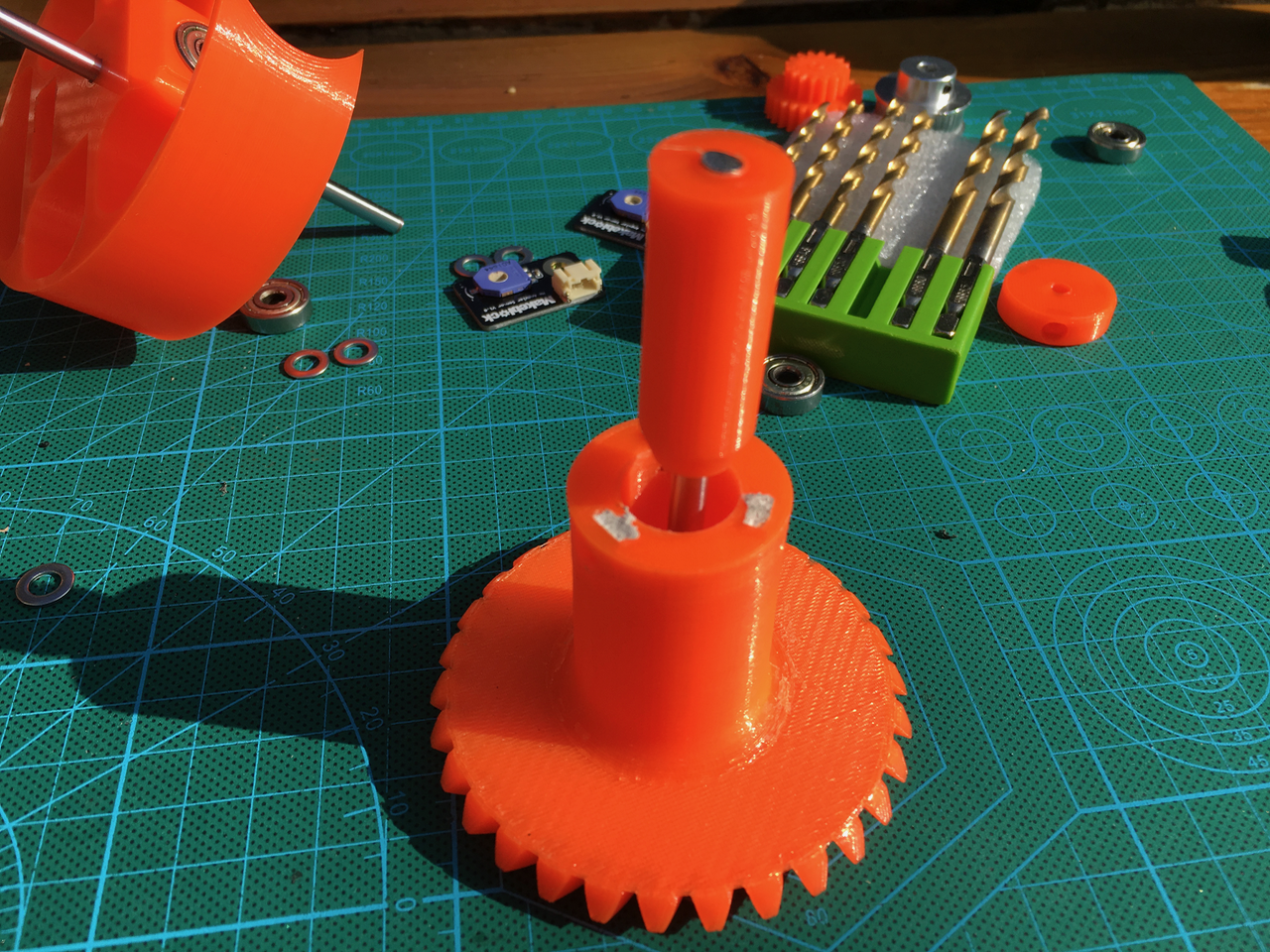
The axle with the holder can now be fitted into the big gear.
My version was 15mm and the hole is 16mm so I used some tape to make the axle a little bit wider. The downloadable version is 15.5 mm. (it has to be removable)
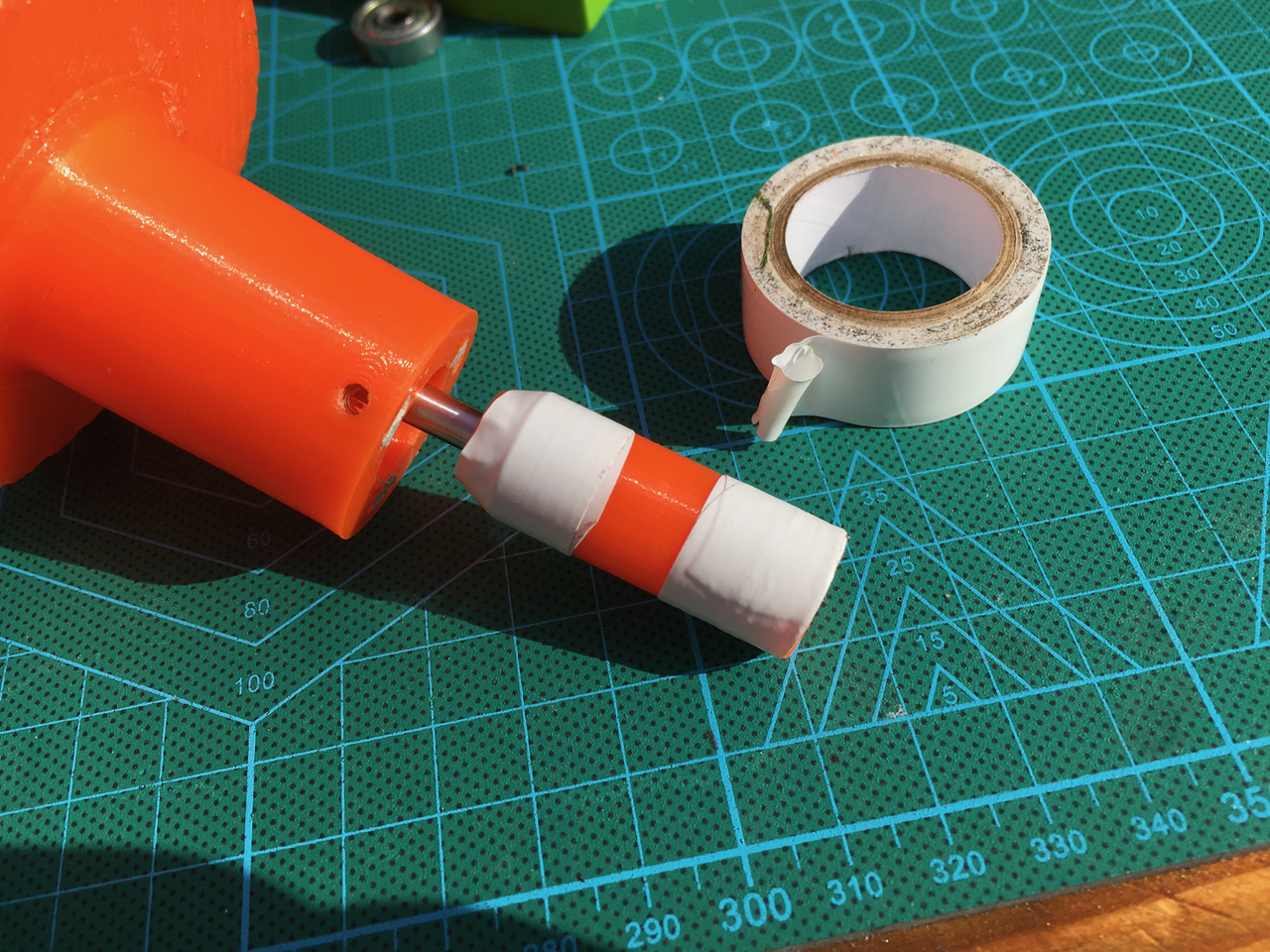
To make the rotation sensor work the Axle has to be fixed inside the gear. This way it is still removable and by using the 3 screws for the Art56Interface it is possible to keep everything in the right place.
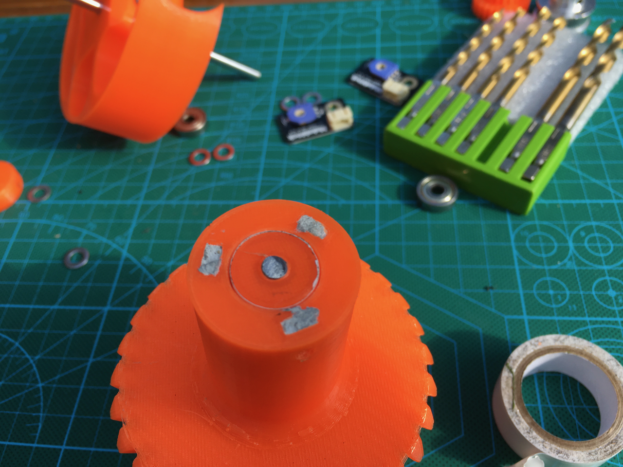
Add 2 M5 spacers.
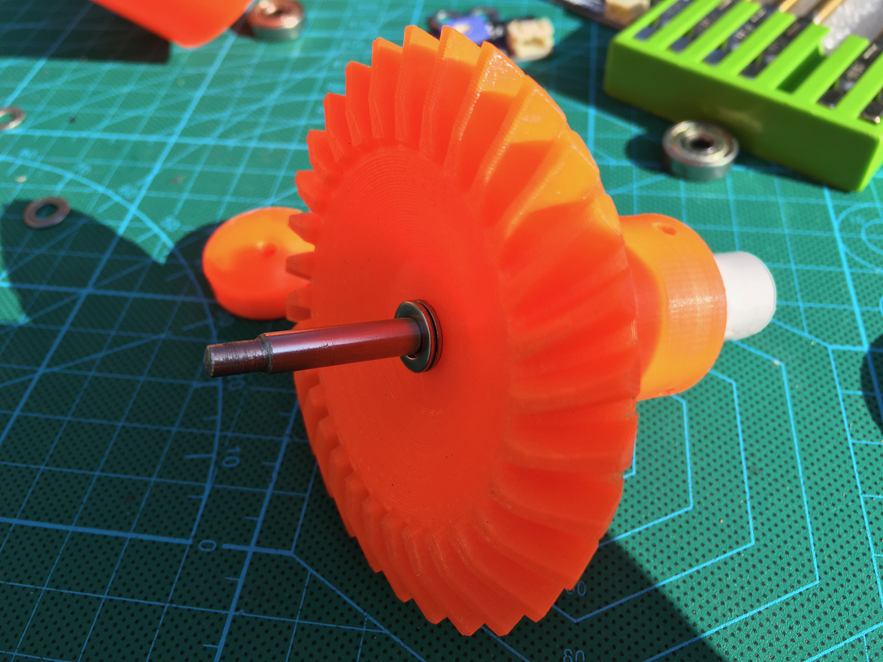
And mount everything together.

Make sure the gears align perfectly. It is possible to remove or add a M5 spacers (two steps up) to change the gap between the gears.

This is how it will look with the gripper mounted.

There is enough room for the belts. I will have to find a way to wire the rotation sensors.
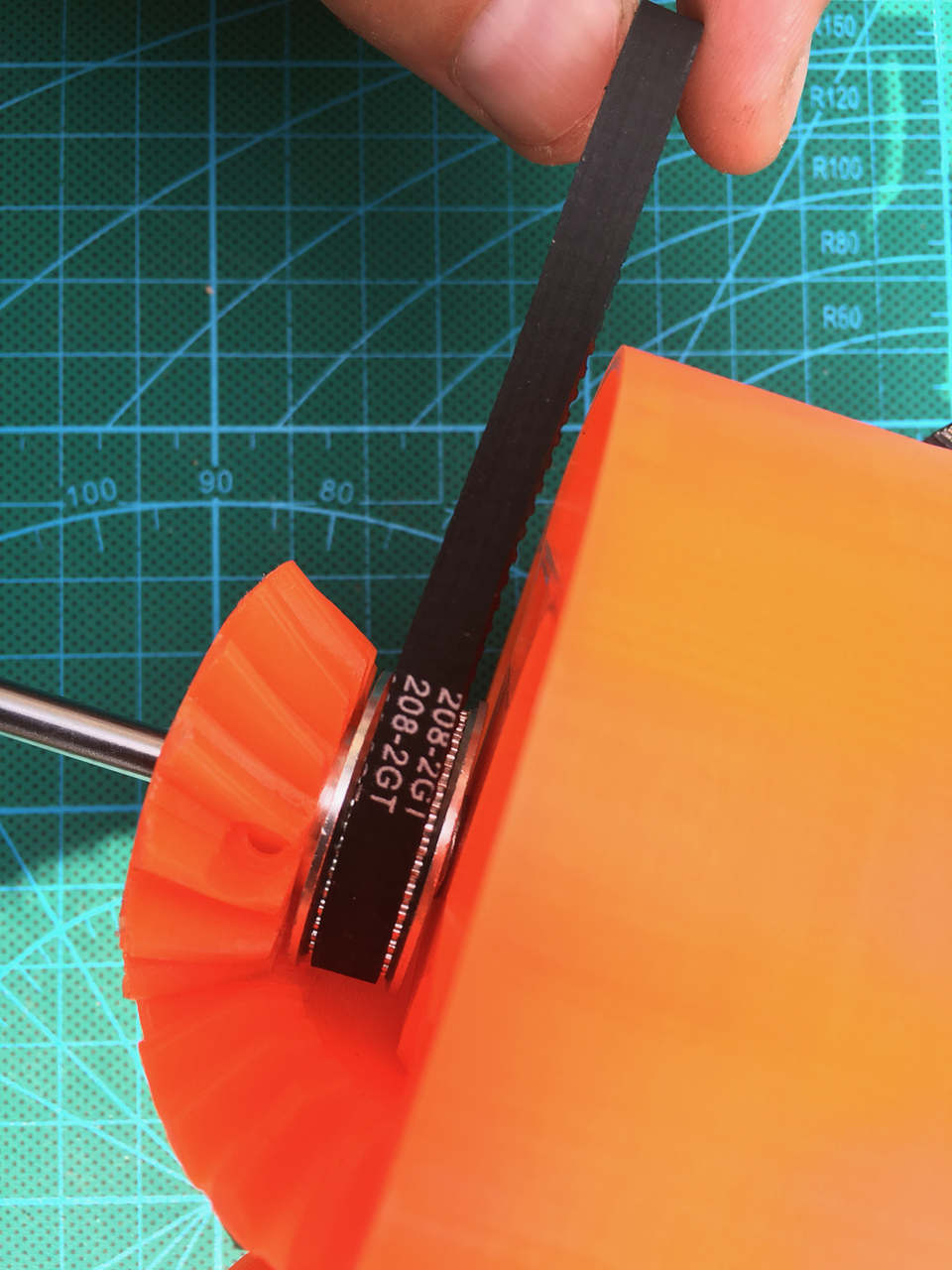
I might drill a hole on the bottom of the ring for the wires. This way the electrical wire will stay out of the belts way.

I am going to change the small gears also. There is about 29 mm room on both sides of the axle. 2 bearings and the pulley are 27mm.
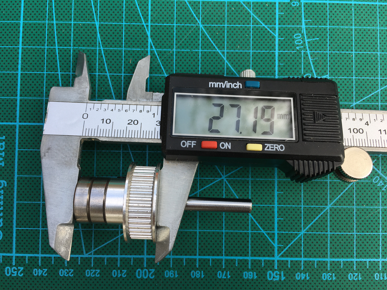
The hole inside the gear is too big. I am going to make the hole smaller for the pulley. And on the other side I will add some plastic to add a bearing. (The gear has to be able to rotate freely on it's axle.
On the axle it will be mounted like this:
- 1 or 2 M5 spacers
- The pulley
- The small gear
- Bearing
- A few M5 spacers
Update:
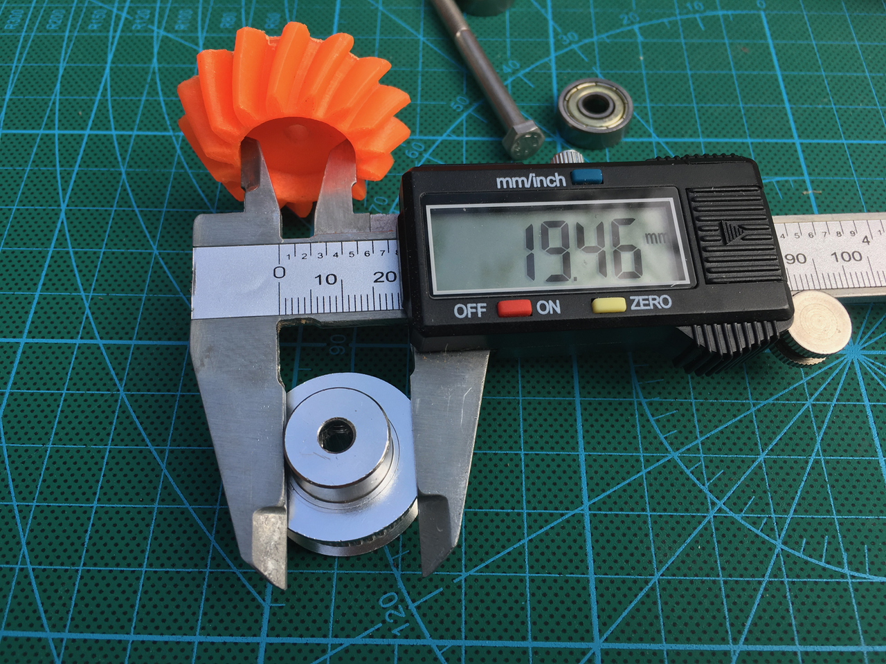
Below the new gears. This is the first version and there are two small problems. The bearing can't go deep enough and the screw hole to fix the pulley and the gear is 0.5mm off. The second version is printing right now. The second version can be downloaded below.
I added a bearing. The axle hole in the plastic gear is a little bit bigger. And I made 2 version. One for a 20x6mm pulley shaft and another for a 16x7mm pulley shaft.
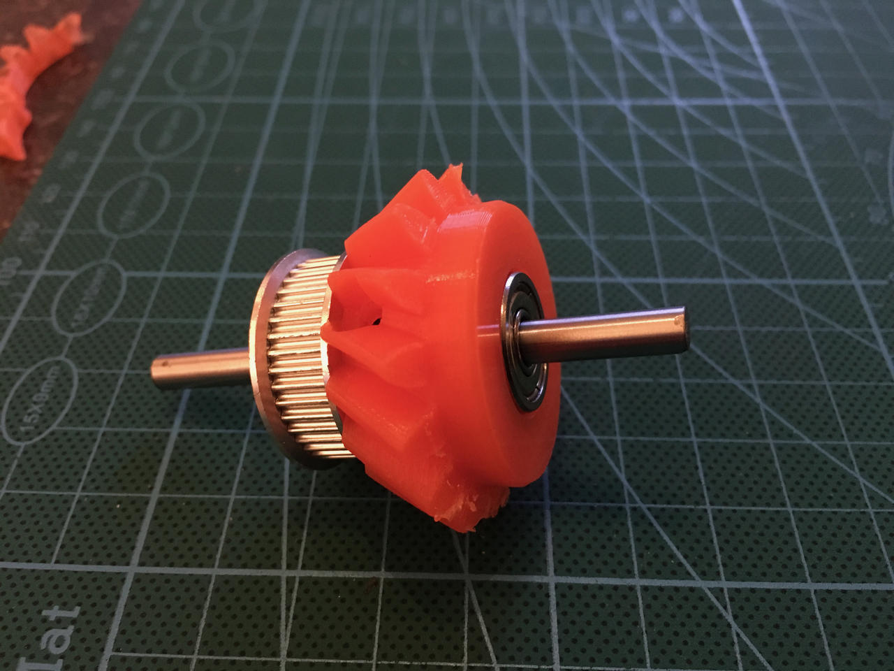
One M5 spacer is needed.

The final result.

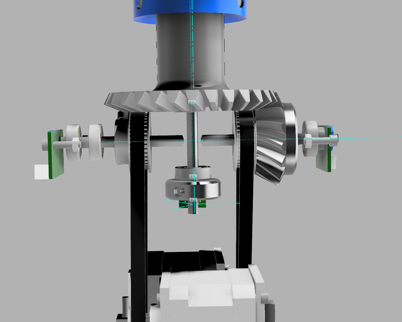
Below the rendering of the new structure.
The changed and new parts can be downloaded here:
- Art56MotorCoverRing_01.stl
- Art56GearPlateAxleHolder_01.stl
- Axle6Fixer.stl
- Art56SmallGear_For16x7PulleyShaft_01.stl
- Art56SmallGear_For20x6PulleyShaft_01.stl
 Sepio
Sepio
Discussions
Become a Hackaday.io Member
Create an account to leave a comment. Already have an account? Log In.
Can I become the step files of the modified parts?
Are you sure? yes | no
Of course: https://drive.google.com/open?id=0B-cMSqnE604uNmZrdU9GMmUxUzA
I am momentarily adding some fans to the Body of Art 4. So this part isn't finished. (I will continue next weekend)
Are you sure? yes | no
Thanks! I want to disassemble my thor again and do the modification like you did, I have changed the software to drive the steppers and feedback sensors. When I put everthing back togetter I will tune everything again to see that it's working good and will put it on my page.
By doing your thing you make the project even better! Top!
Are you sure? yes | no
Which 3D software you use?
Are you sure? yes | no
Fusion 360. It is free for home use
Are you sure? yes | no
Your 3D prints are very good, which filament you use and what kind of printer?
Are you sure? yes | no
I have a Ultimaker 2+ and for this robot arm I used Real filament from 123-3d.nl. They also deliver in Belgium.
I also used some 123-3D “huismerk” filament. It prints fine but it leaves stains on the surface. Look at the black gripper above for an example.
Are you sure? yes | no
I am missing something, the wiring that needs go to the gripper. How would that be done?
Are you sure? yes | no
It goes on the outside. AngelLM has a video which shows the wiring. If the current setup isn’t working I might change the setup again and use a hollow Axle for Axis 6. But this also means I have to use larger and heavier bearings. I don’t know how much extra weight the arm can handle.
Next weekend I am going to add some fans on the Art4body.
Are you sure? yes | no
This design seems very interesting. I always wondered how to montage this part. Was too shaky.
Are you sure? yes | no
I just added the new small gears. The new design is solid as a house.
Are you sure? yes | no