Close
0%
0%

Économique Bionic Leg System

The project emphasizes on providing value for money by using a bionic leg for sprinters embedded with smart monitoring system.

Similar projects worth following
In this project our main focus is to build a smart bionic leg system using basic prosthetic leg and maintaining its quality at the same time by installing a monitoring system which uses components like accelerometer and flex sensor to imitate the other leg's movement and gives signal to the microcontroller unit which is the heart of the system.These Bionic legs are cost friendly and have flexible joints instead of motors so they eliminate the stress caused due to vibration and the user can experience a natural feel instead of an artificial one due to the imitation system.Thus this product is cost friendly and user effective in terms of performance and its calibration can be modified anytime for the benefit of the users.

Need for Bionic Systems

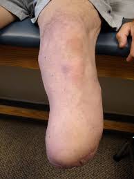
People have always have a craze towards fitness and sports. Ultimately it has lead to the development of sports and several sports are played at international level. It provides entertainment for fans and gives out the importance of physical activities. The tragic part is that some people lose their limbs in accidents and have to lead their life with many difficulties. But Engineers had innovated a new technology known as bionic systems that are artificial/ biological transforms of electro-mechanical systems designed in order to regain their original functionalities.

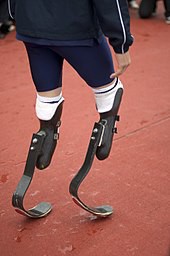


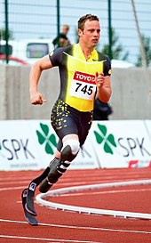
Oscar Pistorious a notable Olympian who made the headlines during the 2012 London Olympics. His both legs were amputed when he was 11 months old. But with the help of prosthetic legs he has achieved greater heights. He won gold in Paralympics held from 2004 to 2012. He achieved a huge milestone by becoming the first amputee to win a non-disabled world track medal. At the 2012 Summer Olympics, Pistorius became the first double-leg amputee to participate in the Olympics. Such has been the influence of prosthetics by making disabled people to lead their life like other normal people.

He has set a benchmark in this world that disabled athletes can take part not only in Paralympics but also in normal Olympics just like Oscar by using bionics. 

Disadvantages

Since its development people have raised lot of doubts regarding its functionality that these bionic systems could help people will it make the player regain his original abilities or boost with artificial technologies that makes them even better than normal individuals such as giving extra thrust during play. This has been a great issue in recent days and people need to know the exact capacity of the players.

The major disadvantage of these systems are they are either developed with an hydraulic system or a micro-controller based system with motorized control that imparts artificial pressure than normal leg. It also provides stress on the knee joints during the long run that makes uncomfortable for the athletes to wear it for a prolonged period. Moreover they are costly as they are manufactured using carbon fiber.

Proposed Solution

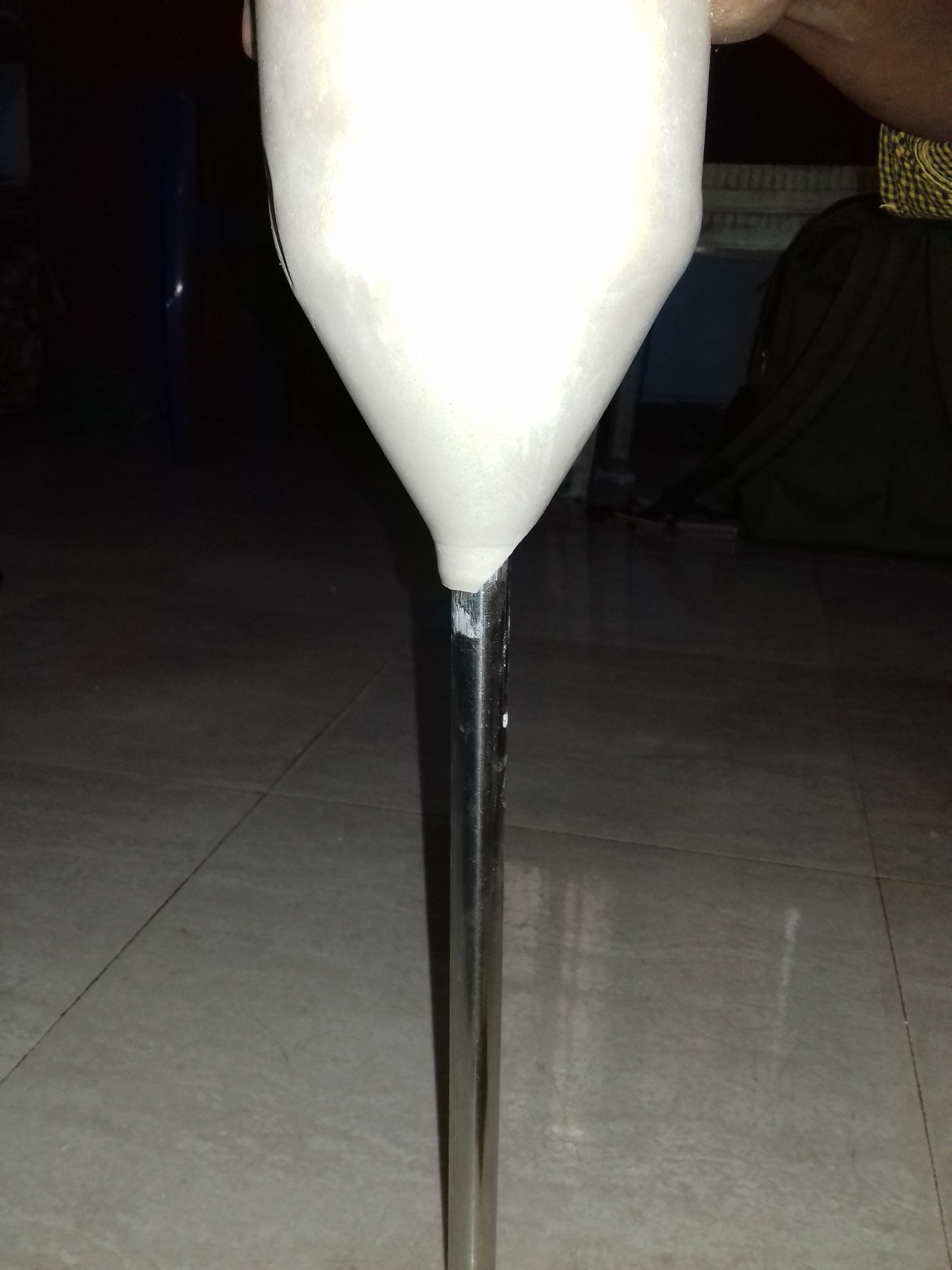
We are developing a 60$ bionic leg fused with smart system that comprises of micro-controller and sensors to monitor the performance instantly. Instead of using high cost carbon fibre we are using silicon rubber as an alternative that has almost similar characteristics of light weight and great strength. This silicon rubber is made into a mold for housing the knee joint(amputated region). The bottom portion of this joint is connected to a shoe by means of a industrial grade steel rod. A flexible joint is provided in between the rod and the silicon rubber mold regulating movements with ease. The hollow cylindrical stainless steel section provides good strength and rigidity to athletes performance. Although it adds weight to the whole system we have reduced it by 75% by making it hollow and reducing its thickness as much as possible.

We are also using a accelerometer and flex sensor that are attached to particle photon that transmits data wirelessly to cloud or mobile app for easy visualization of data. Since both the legs will have same properties they are mirror image of another one. First we will measure the activities such as aceleration and flexibility during various events such as walking, running, jogging etc,. by attaching the module to normal leg. It will be attached to the bionic leg after testing it with normal leg. And using these parameters the player will train to imitate the normal leg. Flex sensor will make sure that the flexible joint will not move further after measuring the limits from normal leg. 

This will bring back their original experience that was before losing their leg and helps them to train much better.

BOM.xlsx

Bill Of Materials

sheet - 10.71 kB - 09/04/2017 at 04:24

Download

sbls.fzz

Circuit Connection

fzz - 35.73 kB - 08/22/2017 at 03:12

Download

  • 1 × Particle Photon To obtain sensor values ,to process them and send to cloud
  • 1 × Flex sensor To measure the flexibility values of the knee joint
  • 1 × Particle cloud To send and push data from particle photon
  • 1 × ADXL 335 Analog accelerometer for measuring acceleration values
  • 1 × Thingspeak cloud To obtain sensor values and display them by means of graph or other gui

View all 10 components

  • What's Next?

    PremJ2009/04/2017 at 10:52 0 comments

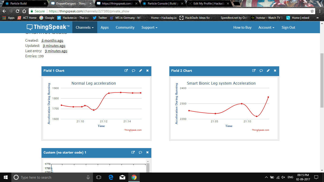
    We have obtained acceleration data from normal leg & bionic leg and analysed them so as to perfectly make the bionic leg imitate the normal leg characteristics.

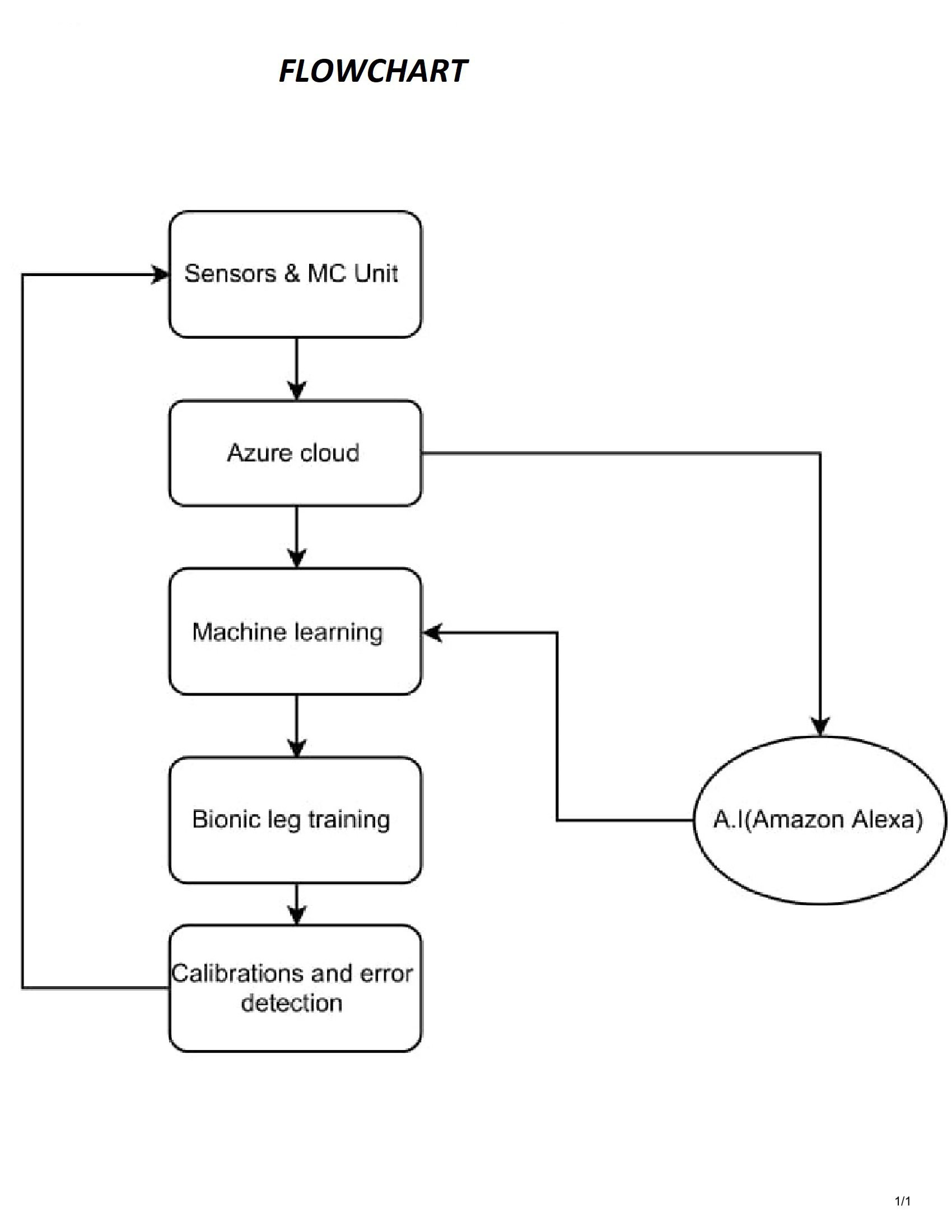
    A simple machine learning part would solve this problem. We are looking at incorporating Microsoft machine learning studio and azure cloud for obtaining the data from the sensors and training the bionic leg.

    In addition to that we are also having the idea of deploying an A.I (Amazon Alexa , Google Home etc) to provide assistance and monitor to user's biological data and the integrity of the bionic system in the leg. This A.I is also based on machine learning so its possible for it to adapt to the operation of the bionic leg system.

    Also the AI can give voice assistance during training sessions for calibration and adjustment of the bionic leg according to the other leg.

  • Sensors infusion and Data analysis

    G.Vignesh09/02/2017 at 17:29 0 comments

    In the previous log we had mentioned in detail about the usage and the advantages of the components. Now we have programmed the Since it is the beginning stage, we have used a simple 3-axis analog accelerometer and a flex sensor to measure knee movements and acceleration. Further we are aiming to use relatively low cost but highly precise low cost 9-axis accelerometer such as MPU-9250(https://www.sparkfun.com/products/13762) that could be vital for this project. 

    Using the data obtained from the sensors we can use it to analyse the readings of the normal leg and using those data we can train the amputated leg attached with smart economique bionic leg system. 

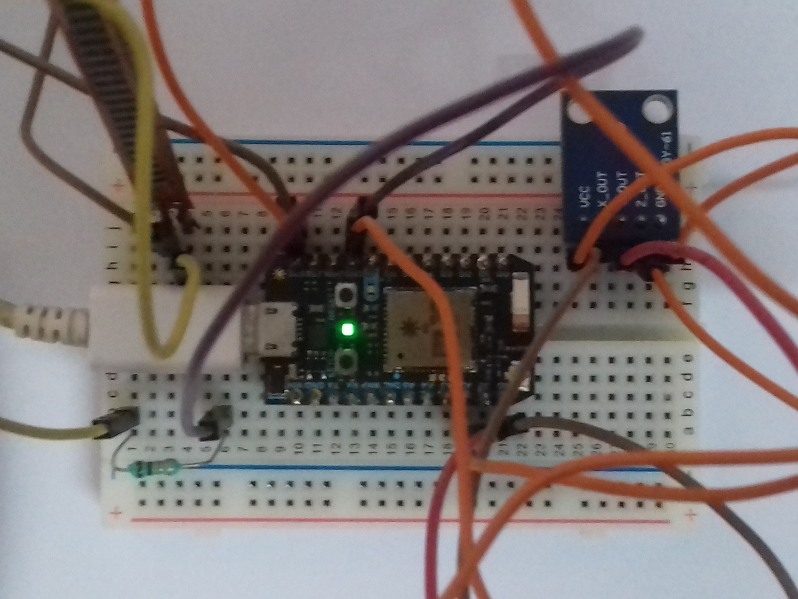
    We have used particle photon and its dedicated particle cloud to visualize the data and events.


    Using Particle IDE and Webhooks

    Click the below mentioned link and sign up into particle.io 

    https://build.particle.io/

    Enter the necessary details and attach your particle photon to a computer. Upgrade the firmware and open the code editor. Enter the code that I have mentioned in the github repository.

    In order to connect Particle and ThingSpeak together, we need to setup a webhook on Particle. This will make a secure connection from Particle.io to ThingSpeak so that data can be passed back and forth.

    You have two options for settings up the webhook. You can use the Particle CLI Tools or IoT Debugger. 

    IoT Debugger

    • Download a copy of IoT Debugger
    • Open the index.html file in a web browser tab
    • Select Particle
    • Enter your Particle Access Token into the Access Token field
    • Click on "Create Webhook"

    In the Content (JSON) field, enter the following file:

    {    
      "event": "thingSpeakWrite_",  
      "url": "https://api.thingspeak.com/update",  
      "requestType": "POST", 
      "form": {       
      "api_key": "{{k}}",        
      "field1": "{{1}}",       
      "field2": "{{2}}",       
      "field3": "{{3}}",        
      "field4": "{{4}}",        
      "field5": "{{5}}",        
      "field6": "{{6}}",      
      "field7": "{{7}}",       
      "field8": "{{8}}",       
      "lat": "{{a}}",       
      "long": "{{o}}",        
      "elevation": "{{e}}",       
      "status": "{{s}}"   
      },   
      "mydevices": true,   
      "noDefaults": true
    }

    Using Thingspeak

    Go to ThingSpeak.com and Sign In. Select Channels and then My Channels. Create a new channel. Click on API Keys and note the Write API Key and Channel ID.


    Using the general empirical formula make sure that you calculate average acceleration and use it for calculating displacement using MATLAB also.

    avg.acceleration = sqrt((x^2)+(y^2)+(z^2))


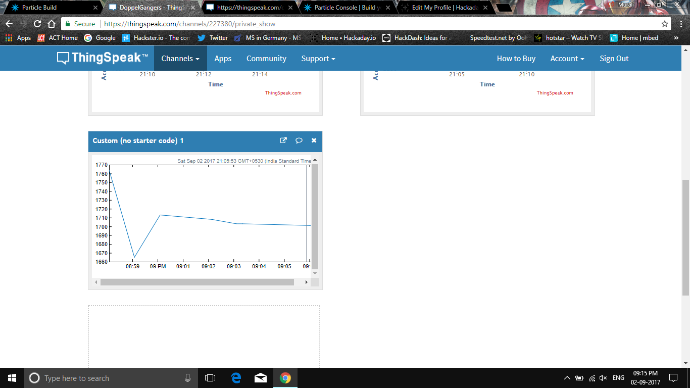
    Below image represents a small MATLAB analysis of displacement data integrated twice from the aceeleration values. 

    Your data is on ThingSpeak you can see this data on ThingSpeak using the MATLAB Visualization. On ThingSpeak, select Apps and then MATLAB Visualizations. Click "New", select "Custom (no starter code), and click "Create".

    Enter the following MATLAB code 

    readChannelID = 227380;
    fieldID1 = 1;
    readAPIKey = '2EP326FSR5MCOFHO';
    %% Read Data %%
    [data, time] = thingSpeakRead(readChannelID, 'Field', fieldID1, 'NumPoints', 10, 'ReadKey', readAPIKey);
    %% Visualize Data %%
    thingSpeakPlot(time, data);

  • Monitoring System Design​​

    PremJ2008/29/2017 at 03:58 0 comments

    In our system design the components used are:

    • Flex sensor
    • 3-axis accelerometer
    • Particle photon

    FLEX SENSOR:

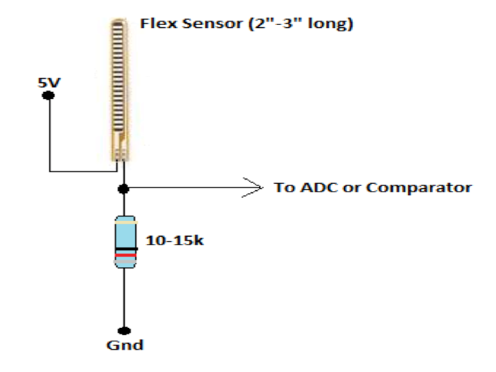
    This flex sensor is a variable resistor like no other. The resistance of the flex sensor increases as the body of the component bends so on one side of the sensor is printed with a polymer ink that has conductive particles embedded in it.
    Left flat, these sensors will look like a 30kΩ resistor. As it bends, the resistance between the two terminals will increase to as much as 70kΩ at a 90° angle.
    By combining the flex sensor with a static resistor to create a voltage divider, you can produce a variable voltage that can be read by a microcontroller’s analog-to-digital converter.

                                                             Flex sensor circuit

    In our project the flex sensor is used to measure the flex angle between knee joint and lower leg.

    3 AXIS ACCELEROMETER (ADXL335):

    An accelerometer is an apparatus used for measuring acceleration or deceleration - that is, the rate of increase or decrease in the velocity of a moving object. Accelerometers are used to measure the efficiency of the braking systems on road and rail vehicles; those used in aircraft and spacecraft can determine accelerations in several directions simultaneously. The measurement of acceleration or one of its derivative properties such as vibration, shock, or tilt . In our project a 3 axis accelerometer is used i.e ADXL335. 

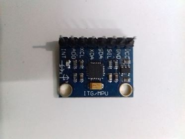
     The ADXL335 is a small, thin, low power, complete 3-axis accelerometer with signal conditioned voltage outputs. The product measures acceleration with a minimum full-scale range of ±3 g. It can measure the static acceleration of gravity in tiltsensing applications, as well as dynamic acceleration resulting from motion, shock, or vibration.

    The user selects the bandwidth of the accelerometer using the CX, CY, and CZcapacitors at the XOUT, YOUT, and ZOUT pins. Bandwidths can be selected to suit the application, with a range of 0.5 Hz to 1600 Hz for X and Y axes, and a range of 0.5 Hz to 550 Hz for the Z axis.

    The ADXL335 is available in a small, low profile, 4 mm × 4 mm × 1.45 mm, 16-lead, plastic lead frame chip scale package (LFCSP_LQ).

                                                                    ADXL 335

                                                     ADXL 335 circuit diagram

    In our project the accelerometer is used to measure the acceleration or movements of the lower leg. Due to the limitations of technological boundaries and cost the 3 axis accelerometer is used. In the future a high precision accelerometer will be taken to consideration.

    PARTICLE PHOTON:

    The Photon is a microcontroller, which is a small, low-cost, low-power computer that can run a single application. The microcontroller runs the software and sends signals to the Photon .

    Microcontrollers are particularly good at controlling things. They have a set of pins that are called GPIO (General Purpose Input and Output) pins, or I/O pins. They can be hooked to sensors or buttons to listen to the world, or they can be hooked to lights and motors to act upon the world. These microcontroller’s pins have been directly connected to the headers on the sides of the Photon so you can easily access them; specifically, the pins labeled D0 to D7 and A0 to A7 are hooked directly to the microcontroller’s GPIO pins.

    The microcontroller can also communicate with other chips using common protocols like Serial (also called UART), SPI, or I2C (also called Wire). You can then make the Photon...

    Read more »

  • The Setup

    G.Vignesh08/27/2017 at 07:23 0 comments

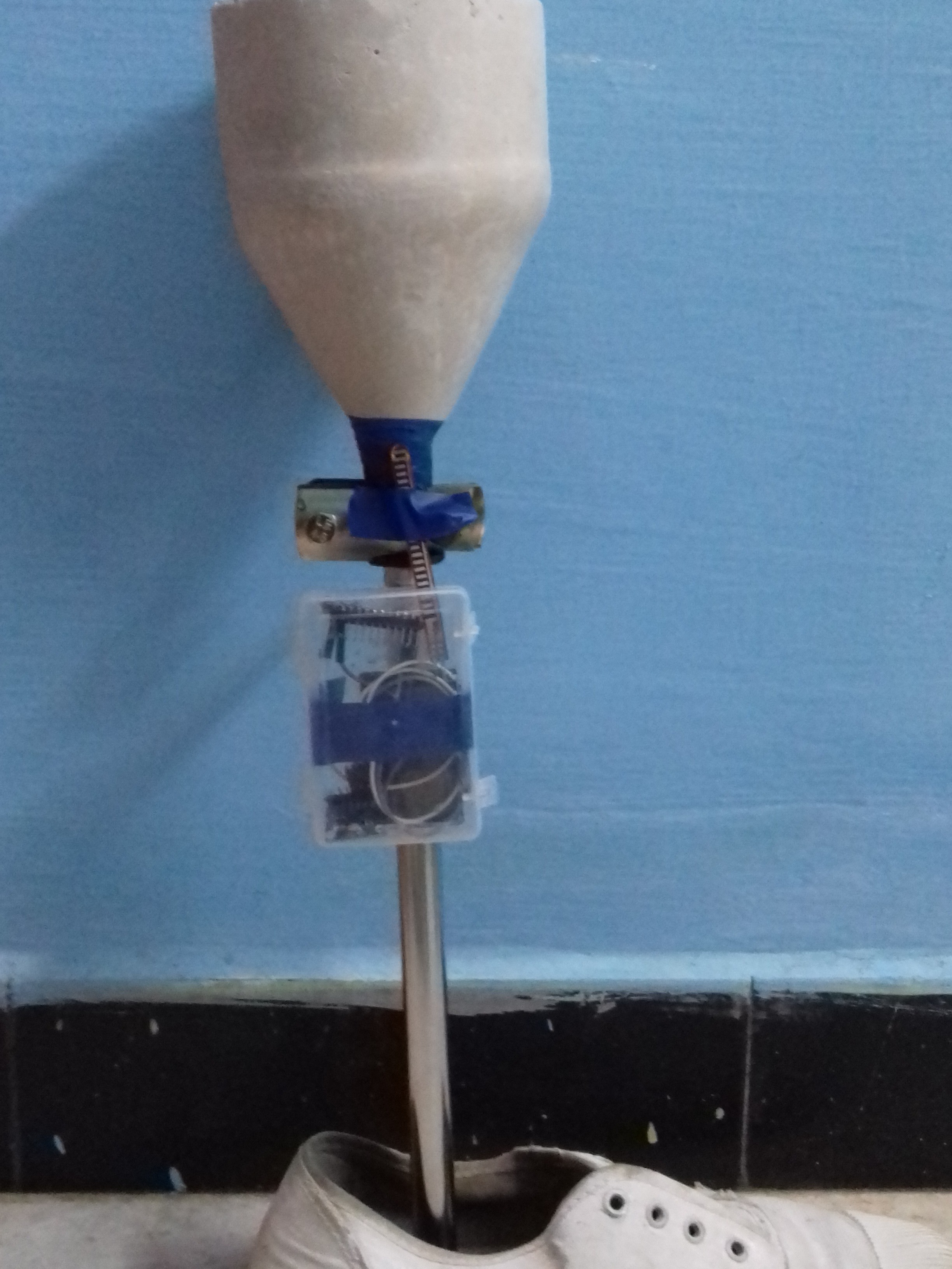
    Since the design of the socket and the connector is completed, it can now be attached to complete the bionic leg. The whole setup is very simple and it consists mainly 3 parts.

    • The Socket

    A simple cast/mold is made from silicone rubber after measuring the dimensions of the knee region. Later we would attach a vacuum suction material so as to perfectly attach the amputated part with the bionic leg. The cost of 1kg of silicone rubber is approximately 15$.

    • The Lower Leg imitator

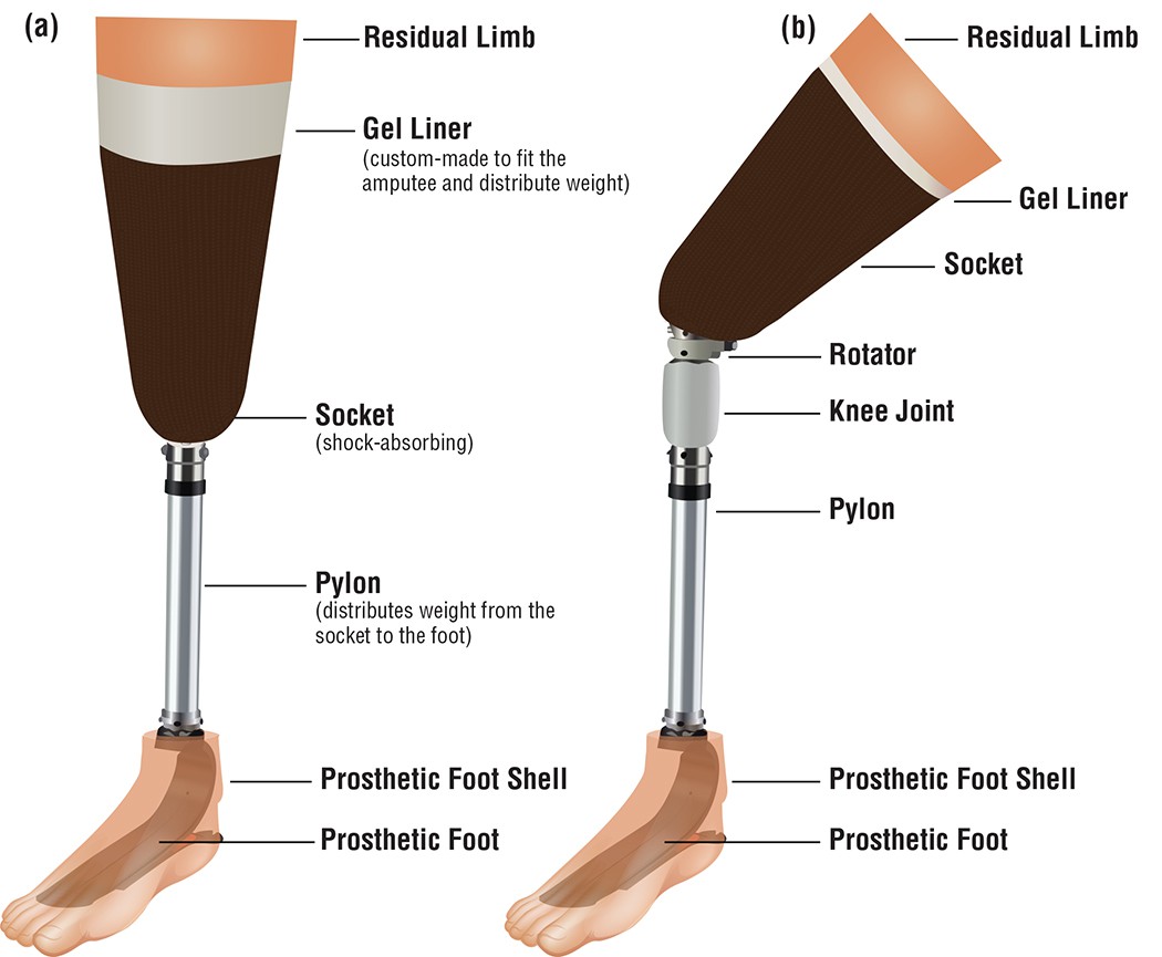
    A customized light weight stainless steel rod was designed and was fixed to the lower region of the socket and the other end being connected to a prosthetic foot/shoe. Make sure the base of the shoe is cushioned enough to withstand the stress during movements and is attached to the steel section tightly. The upper part of this is connected to the socket by means of a rotary coupler. This can be adjusted to make the leg move in desired ways. The cost of steel rod is 7$ and that of rotary coupler is 8$.

    • Sensor Module

    It consists of a small plastic box that incorporates particle photon, accelerometer, flex sensor and a battery. It is attached to the stainless steel rod region present in the bionic leg. The cost of photon is 20$ and the sensors are about 10$ in total.

    The total cost for design is approximately equal to 60$. 

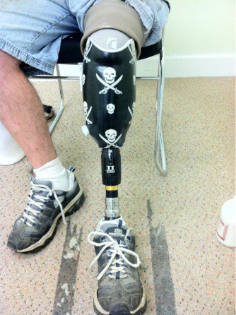
    Below is an image that we expected to bring out of our design. 

    Expected Deisgn

    We obtained a similar kind of model and will be updating this with improvements and ways to reduce the cost further.

  • Design of Connector between the amputated part and foot

    G.Vignesh08/24/2017 at 17:30 0 comments

    In the previous log I had mentioned about the design of the mold for housing the amputated knee region. This mold has to be connected to the foot by some means. There are several parts available in the market which can perform this function. But one thing to be focused is that it should be strong enough to balance the whole weight of the body without any deformity. It should also be light in weight such that the athlete should not feel any kind of stress during action i.e: It should be a mirror image of the other leg with similar weight and must function with ease.

    Why Stainless Steel? Why not Carbon Fibre?

    Of course carbon fibre is comparatively better material than stainless steel. 

    • Carbon fiber is approximately 5 times lighter than typical stainless steel material 1.5 times .
    • Carbon fiber is approximately 3 times stronger than typical stainless steel material.
    • Carbon fiber is nearly 15 times greater than the cost of stainless steel.

    By using the carbon fiber one may reduce the weight of whole structure but will fail in giving balance to the body having right weight proportion as the same weight of tibia.

    Aluminium may be considered as it is 3 times lighter than stainless steel but it is not strong enough as in case of stainless steel.

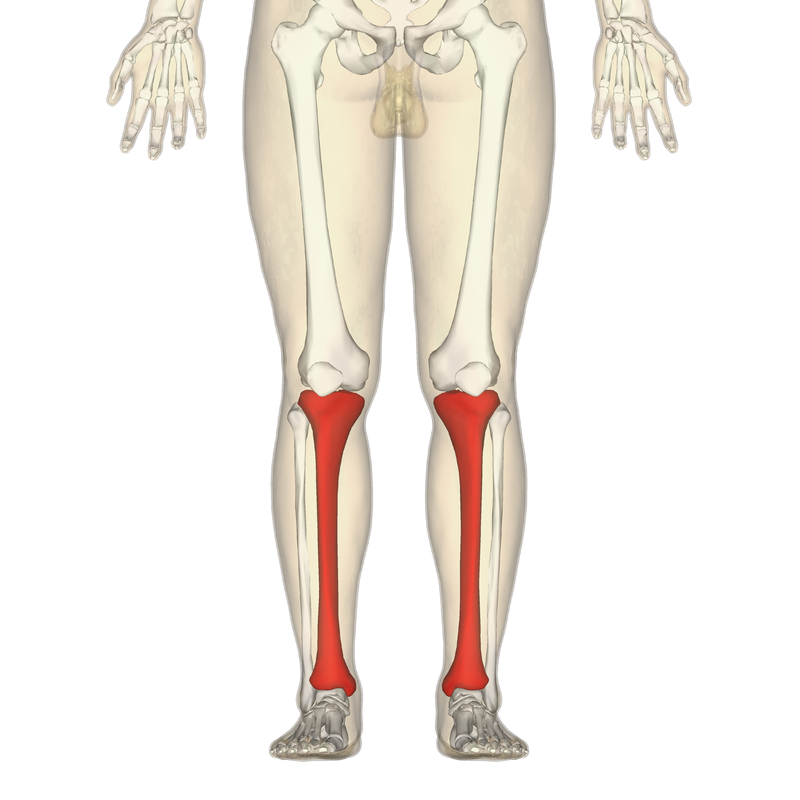
    Since the main aim of developing a bionic/prosthetic replacement for the amputated part we must consider the fact it is going to replace the lower leg or Tibia and Fibula portions in the body. Of these, Tibia is the weight bearing portion. Fibula is also an equally important portion (lighter in weight)  that gives support to the tibia and provides support especially in the foot region. But mimicking the tibia would alone be enough along with some couplers to design the supporting portion. 

    Design and Implementation

    Keeping the above stated factors in mind we considered that physical features of 20 year old disabled athlete of weight 65 kg and height 180 cm. Based on the height and weight features we have designed a custom steel rod. 

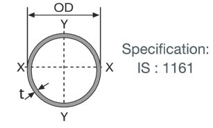
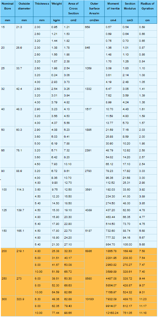
    We have used the below mentioned industrial grade hollow steel section for greater efficiency and enhanced properties. 


    Some of the commonly used hollow steel section produced in industries and their properties are listed below.

    Rotary Coupling

    This plays a important role in the bionic leg movements. The fact is that it should be able to convert the impulses into work by moving the pylon(weight distribution part from mold to leg) in accordance with the amputated part. We are measuring the movements of the other leg by using sensors and using the same values the bionic leg would be used to train and one could adjust the nob according to their wish. 

    Rotary Coupler for the Bionic limb

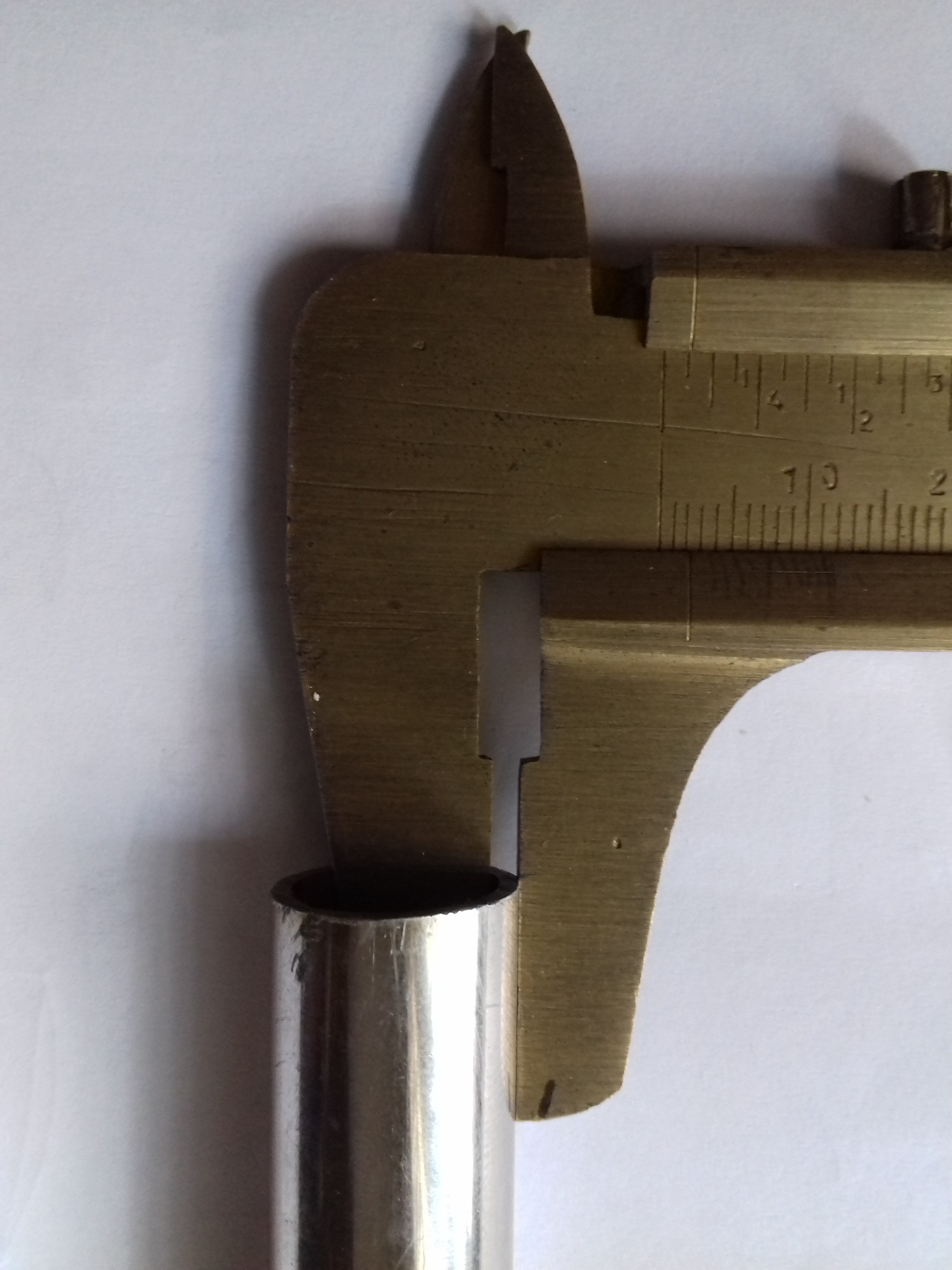
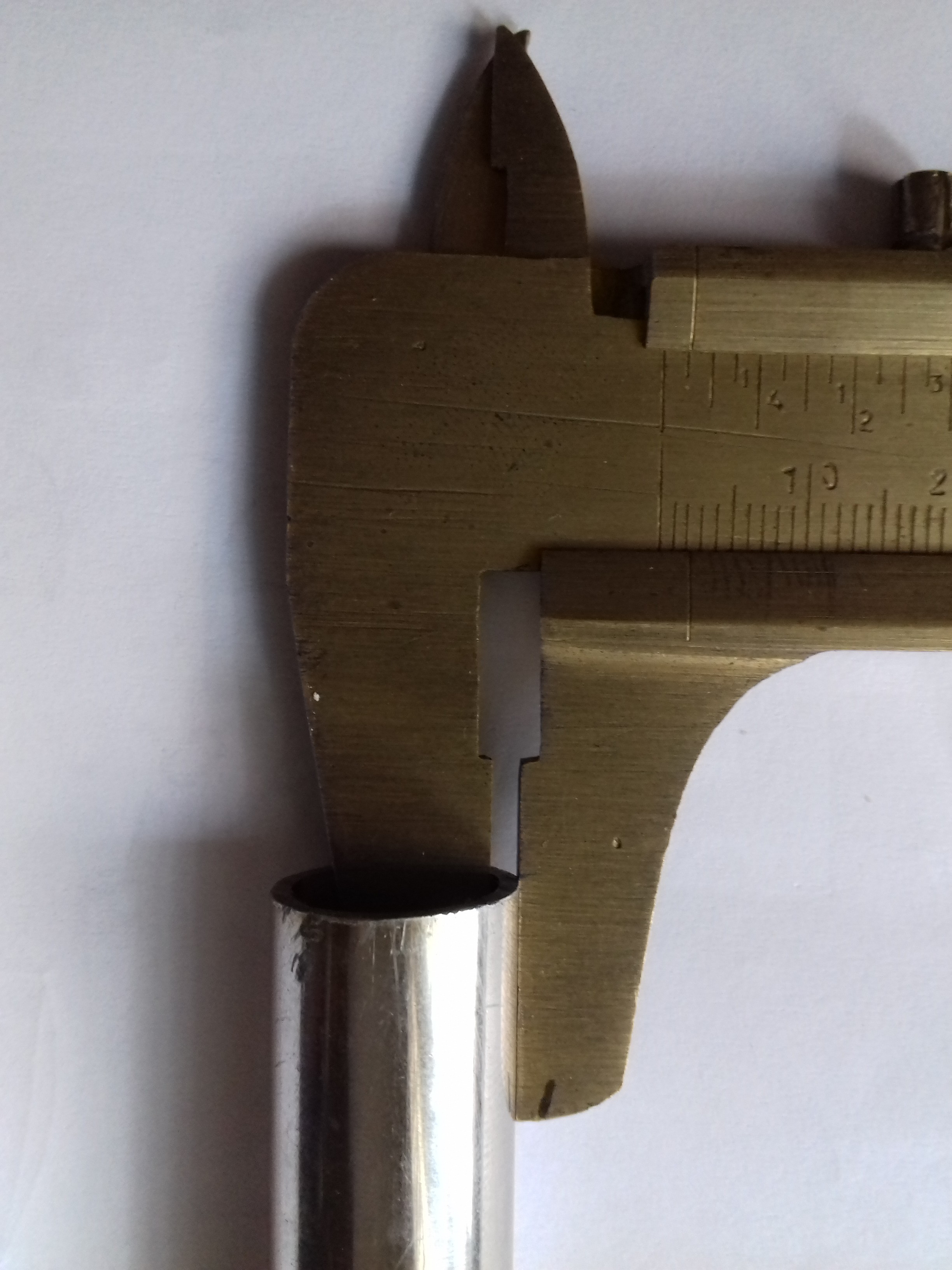
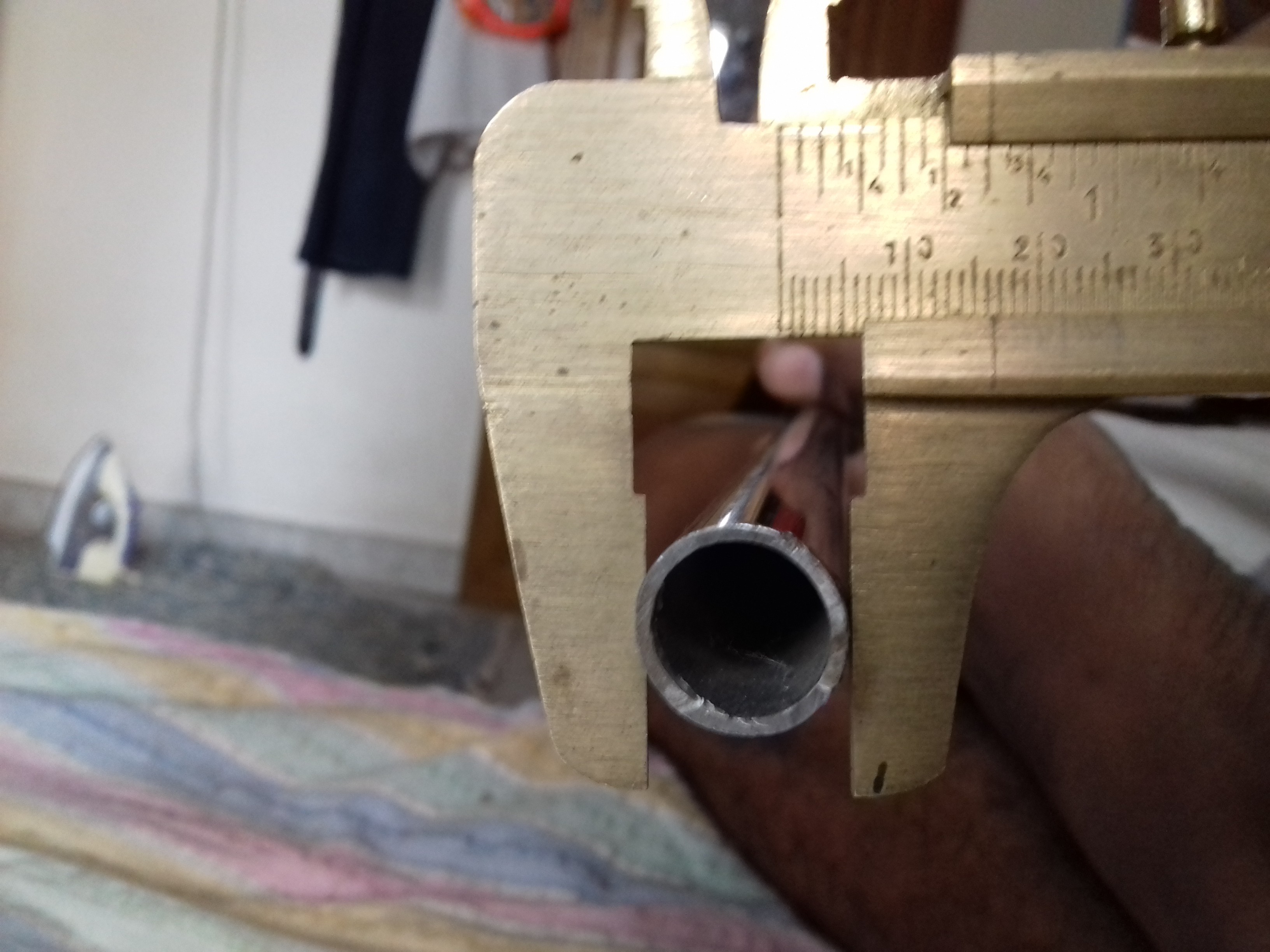
    We used a vernier caliper to measure, so that it becomes precise. The hollow stainless steel section that we have ordered a steel section of 

    • Length 310 mm(31 cm)
    • Thickness is about 1.5 mm 
    • Outer diameter - 16 mm. 
    • Area of cross section - 0.68 sq.cm
    • Weight - 0.51 kg
    • Maximum bearable weight - 500 kg

    The other end could be connected to a prosthetic foot or shoe to complete the whole system.

  • Preparing the Socket for housing the knee region

    G.Vignesh08/22/2017 at 17:17 0 comments

    This mould is the special material to house the amputated knee or simply it acts as a major connection between knee and the foot. Many prosthetics that have been in the market lately have used carbon fibre as the base. Although carbon fibre is strong the major factor to be considered is that the prosthetic should not be an added weight which may result in excessive stress during movements. It should be light and must satisfy the criteria it is essentially strong to withstand the weight of the whole body. You can even 3D print the mould but that's gonna cost atleast 35$! If you would still like to 3D print the module I have attached the STL file and you could make some modifications and 3D print the mould.

    You can even check out in this website http://3dprintingpricecheck.com/


    Why silicone rubber?

    The mould for housing the knee region can be made from any material keeping in mind the important factor- it doesn't deform in size or shape and is able to withstand the thrust of the athlete. Some of them that are used are mostly in the form of carbon fiber polymer. Carbon fibre polymers are of high cost but with great properties. Since we decided to develop the whole prototype within 50$ we founded an alternative in the form of Silicone Rubber. 

    It is far cheaper than other materials and has almost similar properties to that of the carbon fiber and that makes it as the best choice. Silicone rubber is an elastomer (rubber-like material) composed of silicone—itself a polymer—containing silicon together with carbon, hydrogen, and oxygen. Silicone rubbers are widely used in industry, and there are multiple formulations. Silicone rubbers are often one- or two-part polymers, and may contain fillers to improve properties or reduce cost. Silicone rubber is generally non-reactive, stable, and resistant to extreme environments and temperatures from -55 °C to +300 °C while still maintaining its useful properties. Due to these properties and its ease of manufacturing and shaping, silicone rubber can be found in a wide variety of products, including: automotive applications; cooking, baking, and food storage products; apparel such as undergarments, sportswear, and footwear; electronics; medical devices and implants; and in home repair and hardware with products such as silicone sealants. To see the full properties of Silicon Rubber Polymer 

    https://www.azom.com/properties.aspx?ArticleID=920

    We used this silicone rubber mould making material from amazon http://www.amazon.in/MoldSil-15-Mold-Making-Silicon/dp/B06WGMCSSZ?tag=googinhydr18418-21


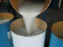
    We used water bottle as the base to make the mould and and a solid to make the mould hollow. The process is so simple and could be done within minutes. It takes few hours for the liquid to turn into a perfect solid resulting in Silicon Rubber. Before it dries up attach one end of the laces preferably velcro in the mould so that we could tie the bionic leg to our thigh region.

    While making mould make sure to measure the diameter of knee and add few millimeters for placing the cushiony  material. The dimensions of the mould that we made has a radius of 5cm, height of 10cm, volume of 215 cub.cm and a surface area of 36 sq.cm. Make sure that the mould is completely dried up so that it retains its properties. Drill up a hole underneath the mould so as to place the stainless steel rod. In the hollow region of the mould place some cotton material that acts as a cushion.

    Further we would be adding an adjustable vacuum suction part such that it becomes easy for the athlete to attach the amputated region to the socket easily!

View all 6 project logs

Enjoy this project?

Share

Discussions

David H Haffner Sr wrote 08/24/2017 at 15:16 point

A very interesting project you have here, I like it!

  Are you sure? yes | no

PremJ20 wrote 08/24/2017 at 15:37 point

Thank you sir it means a lot to us

  Are you sure? yes | no

David H Haffner Sr wrote 08/24/2017 at 15:48 point

An honest compliment to a serious project :)

  Are you sure? yes | no

Similar Projects

Does this project spark your interest?

Become a member to follow this project and never miss any updates