PremJ20
-
What's Next?
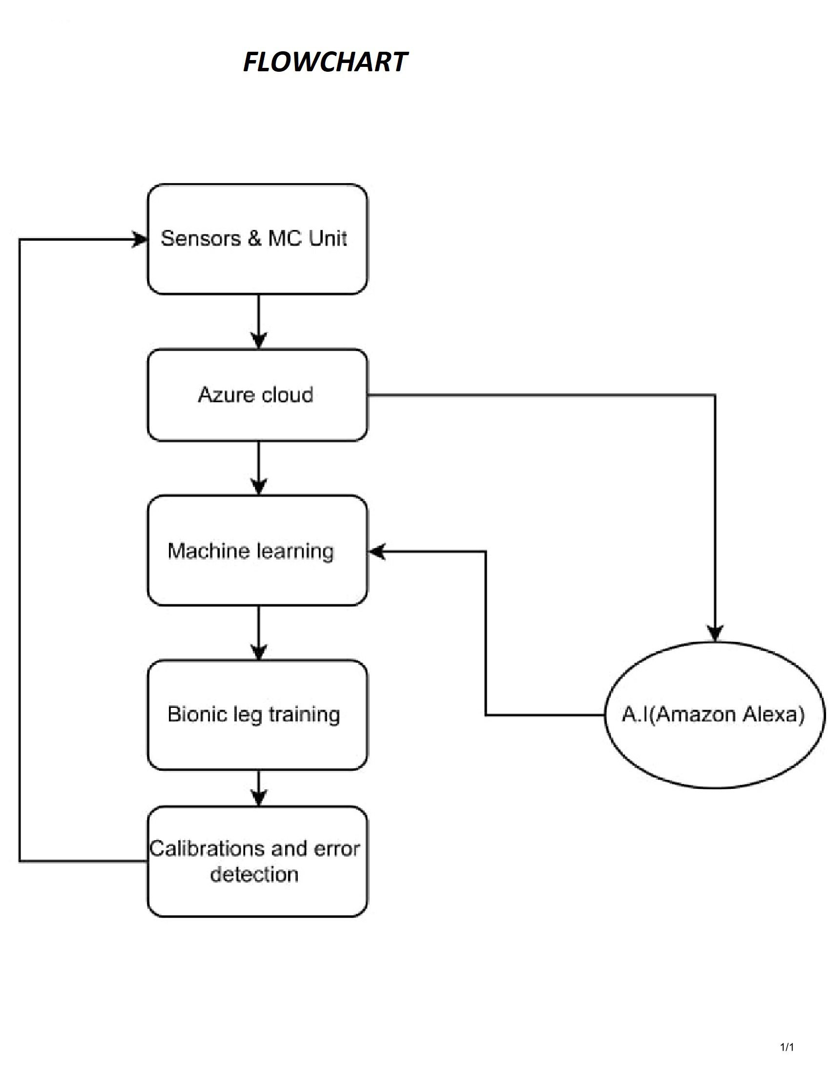
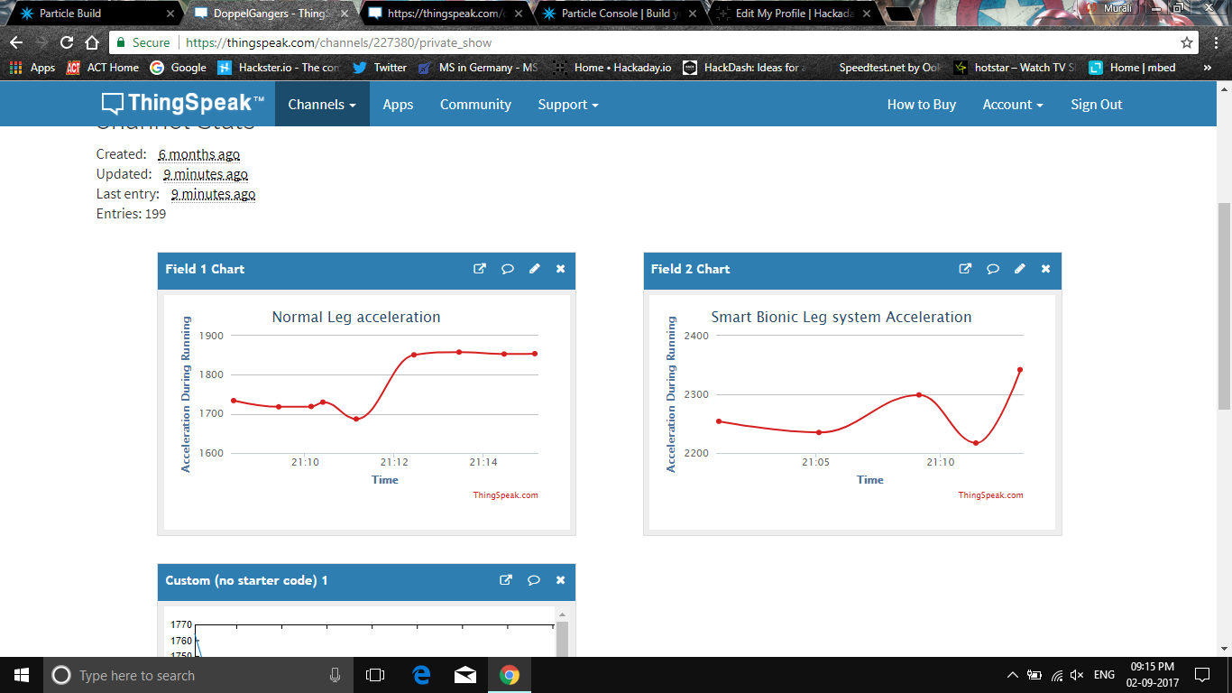
09/04/2017 at 10:52 • 0 commentsWe have obtained acceleration data from normal leg & bionic leg and analysed them so as to perfectly make the bionic leg imitate the normal leg characteristics.
A simple machine learning part would solve this problem. We are looking at incorporating Microsoft machine learning studio and azure cloud for obtaining the data from the sensors and training the bionic leg.
In addition to that we are also having the idea of deploying an A.I (Amazon Alexa , Google Home etc) to provide assistance and monitor to user's biological data and the integrity of the bionic system in the leg. This A.I is also based on machine learning so its possible for it to adapt to the operation of the bionic leg system.
Also the AI can give voice assistance during training sessions for calibration and adjustment of the bionic leg according to the other leg.
![]()
-
Sensors infusion and Data analysis
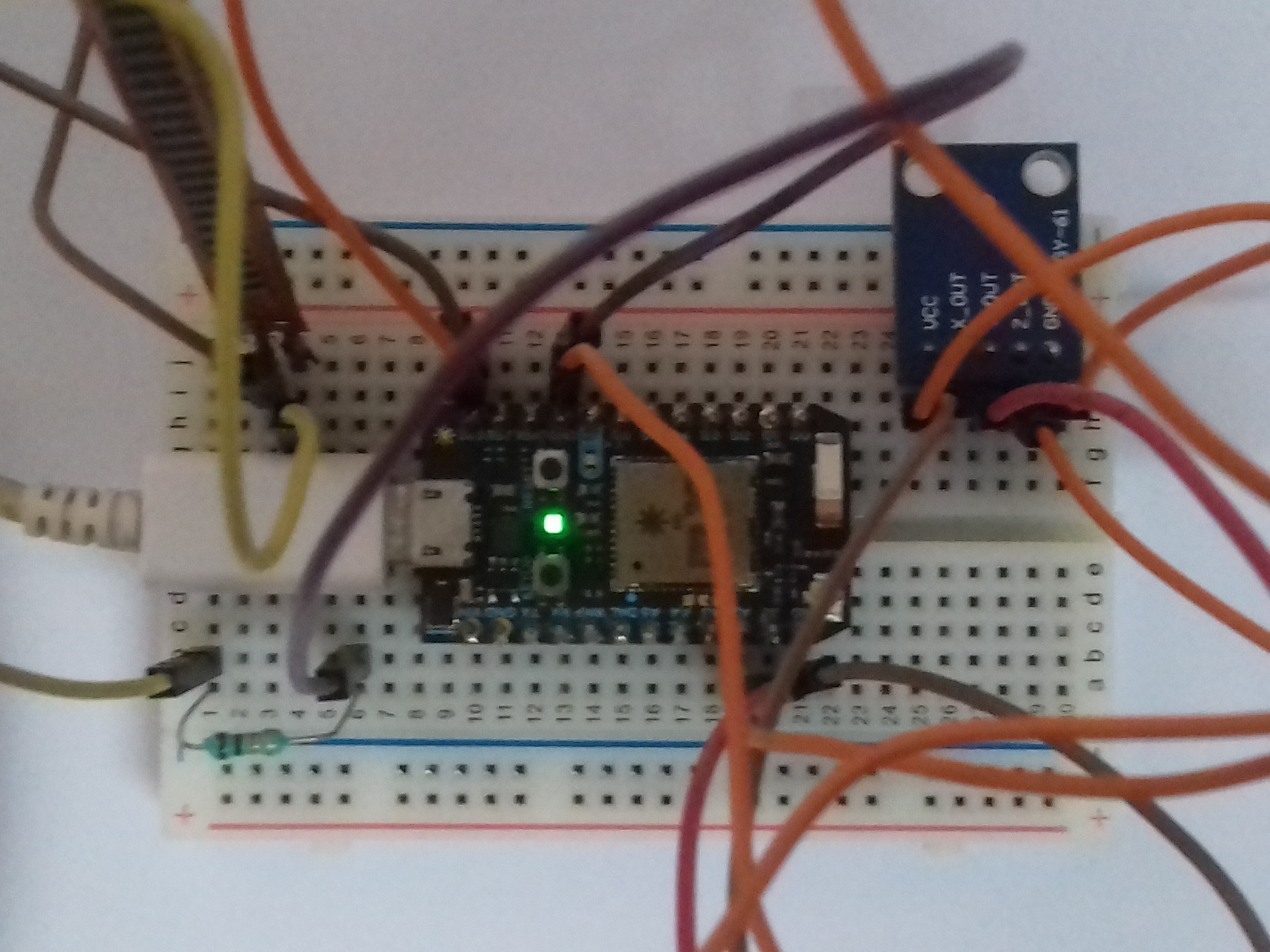
09/02/2017 at 17:29 • 0 commentsIn the previous log we had mentioned in detail about the usage and the advantages of the components. Now we have programmed the Since it is the beginning stage, we have used a simple 3-axis analog accelerometer and a flex sensor to measure knee movements and acceleration. Further we are aiming to use relatively low cost but highly precise low cost 9-axis accelerometer such as MPU-9250(https://www.sparkfun.com/products/13762) that could be vital for this project.
Using the data obtained from the sensors we can use it to analyse the readings of the normal leg and using those data we can train the amputated leg attached with smart economique bionic leg system.
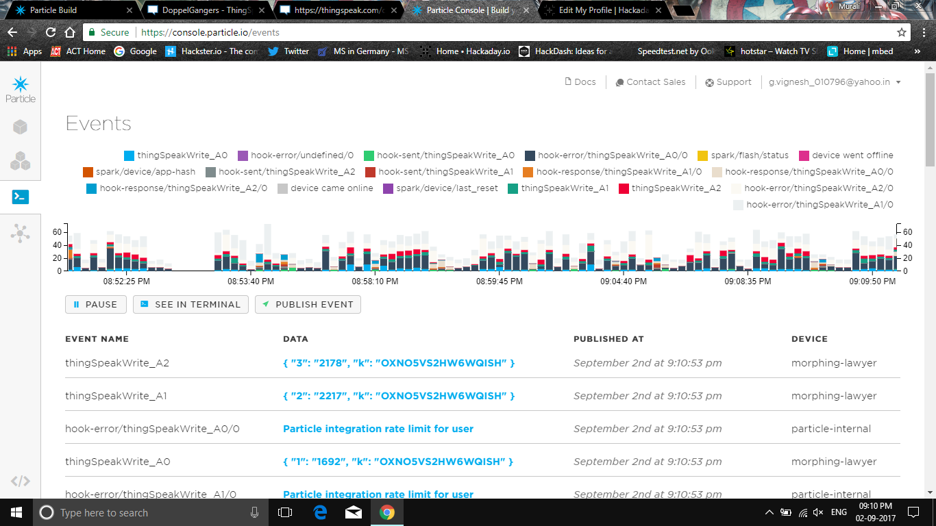
We have used particle photon and its dedicated particle cloud to visualize the data and events.
Using Particle IDE and Webhooks
Click the below mentioned link and sign up into particle.io
Enter the necessary details and attach your particle photon to a computer. Upgrade the firmware and open the code editor. Enter the code that I have mentioned in the github repository.
In order to connect Particle and ThingSpeak together, we need to setup a webhook on Particle. This will make a secure connection from Particle.io to ThingSpeak so that data can be passed back and forth.
You have two options for settings up the webhook. You can use the Particle CLI Tools or IoT Debugger.
IoT Debugger
- Download a copy of IoT Debugger
- Open the index.html file in a web browser tab
- Select Particle
- Enter your Particle Access Token into the Access Token field
- Click on "Create Webhook"
In the Content (JSON) field, enter the following file:
{
  "event": "thingSpeakWrite_",
  "url": "https://api.thingspeak.com/update",
  "requestType": "POST",
  "form": {
  "api_key": "{{k}}",
  "field1": "{{1}}",
  "field2": "{{2}}",
  "field3": "{{3}}",
  "field4": "{{4}}",
  "field5": "{{5}}",
  "field6": "{{6}}",
  "field7": "{{7}}",
  "field8": "{{8}}",
  "lat": "{{a}}",
  "long": "{{o}}",
  "elevation": "{{e}}",
  "status": "{{s}}"
  },
  "mydevices": true,
  "noDefaults": true
}
Using Thingspeak
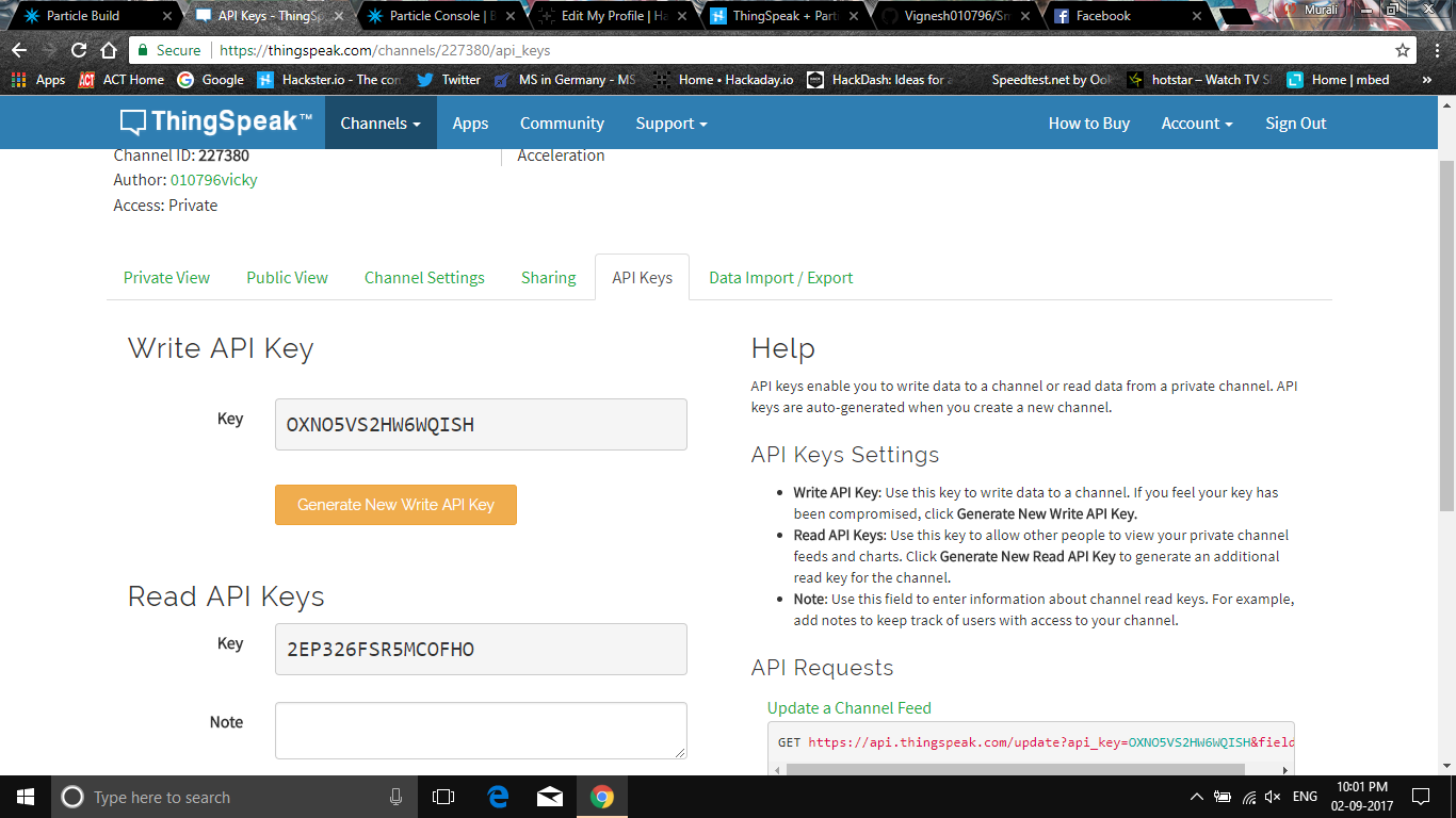
Go to ThingSpeak.com and Sign In. Select Channels and then My Channels. Create a new channel. Click on API Keys and note the Write API Key and Channel ID.
Using the general empirical formula make sure that you calculate average acceleration and use it for calculating displacement using MATLAB also.
avg.acceleration = sqrt((x^2)+(y^2)+(z^2))
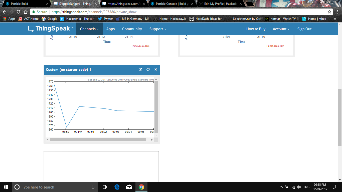
Below image represents a small MATLAB analysis of displacement data integrated twice from the aceeleration values.
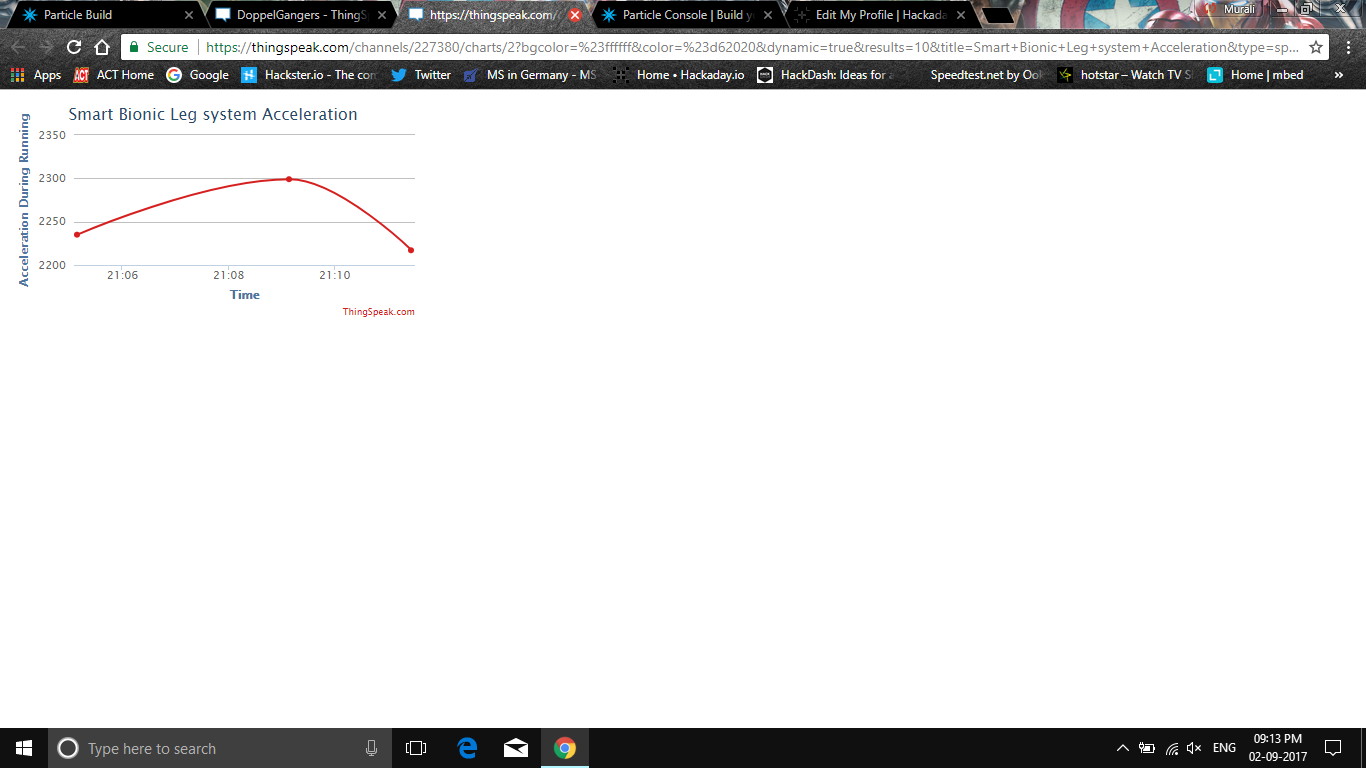
Your data is on ThingSpeak you can see this data on ThingSpeak using the MATLAB Visualization. On ThingSpeak, select Apps and then MATLAB Visualizations. Click "New", select "Custom (no starter code), and click "Create".
Enter the following MATLAB code
readChannelID = 227380;
fieldID1 = 1;
readAPIKey = '2EP326FSR5MCOFHO';
%% Read Data %%
[data, time] = thingSpeakRead(readChannelID, 'Field', fieldID1, 'NumPoints', 10, 'ReadKey', readAPIKey);
%% Visualize Data %%
thingSpeakPlot(time, data);
-
Monitoring System Design
08/29/2017 at 03:58 • 0 commentsIn our system design the components used are:
- Flex sensor
- 3-axis accelerometer
- Particle photon
FLEX SENSOR:
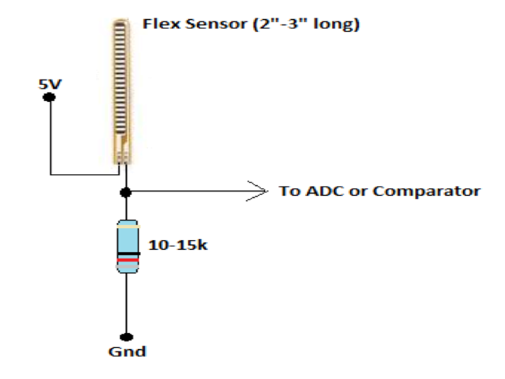
This flex sensor is a variable resistor like no other. The resistance of the flex sensor increases as the body of the component bends so on one side of the sensor is printed with a polymer ink that has conductive particles embedded in it.
Left flat, these sensors will look like a 30kΩ resistor. As it bends, the resistance between the two terminals will increase to as much as 70kΩ at a 90° angle.
By combining the flex sensor with a static resistor to create a voltage divider, you can produce a variable voltage that can be read by a microcontroller’s analog-to-digital converter.Flex sensor circuit
In our project the flex sensor is used to measure the flex angle between knee joint and lower leg.
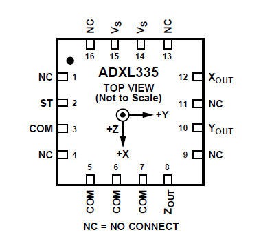
3 AXIS ACCELEROMETER (ADXL335):
An accelerometer is an apparatus used for measuring acceleration or deceleration - that is, the rate of increase or decrease in the velocity of a moving object. Accelerometers are used to measure the efficiency of the braking systems on road and rail vehicles; those used in aircraft and spacecraft can determine accelerations in several directions simultaneously. The measurement of acceleration or one of its derivative properties such as vibration, shock, or tilt . In our project a 3 axis accelerometer is used i.e ADXL335.
The ADXL335 is a small, thin, low power, complete 3-axis accelerometer with signal conditioned voltage outputs. The product measures acceleration with a minimum full-scale range of ±3 g. It can measure the static acceleration of gravity in tiltsensing applications, as well as dynamic acceleration resulting from motion, shock, or vibration.
The user selects the bandwidth of the accelerometer using the CX, CY, and CZcapacitors at the XOUT, YOUT, and ZOUT pins. Bandwidths can be selected to suit the application, with a range of 0.5 Hz to 1600 Hz for X and Y axes, and a range of 0.5 Hz to 550 Hz for the Z axis.
The ADXL335 is available in a small, low profile, 4 mm × 4 mm × 1.45 mm, 16-lead, plastic lead frame chip scale package (LFCSP_LQ).
![]()
ADXL 335
![]() ADXL 335 circuit diagram
ADXL 335 circuit diagramIn our project the accelerometer is used to measure the acceleration or movements of the lower leg. Due to the limitations of technological boundaries and cost the 3 axis accelerometer is used. In the future a high precision accelerometer will be taken to consideration.
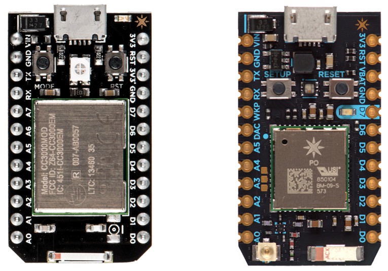
PARTICLE PHOTON:
The Photon is a microcontroller, which is a small, low-cost, low-power computer that can run a single application. The microcontroller runs the software and sends signals to the Photon .
Microcontrollers are particularly good at controlling things. They have a set of pins that are called GPIO (General Purpose Input and Output) pins, or I/O pins. They can be hooked to sensors or buttons to listen to the world, or they can be hooked to lights and motors to act upon the world. These microcontroller’s pins have been directly connected to the headers on the sides of the Photon so you can easily access them; specifically, the pins labeled D0 to D7 and A0 to A7 are hooked directly to the microcontroller’s GPIO pins.
The microcontroller can also communicate with other chips using common protocols like Serial (also called UART), SPI, or I2C (also called Wire). You can then make the Photon more powerful by connecting it to special-purpose chips like motor drivers or shift registers. Sometimes we’ll wrap up these chips on a Shield, an accessory to the Photon that makes it easy to extend the Photon.
The Photon also has a Wi-Fi module, which connects it to your local Wi-Fi network in the same way that your computer or smartphone might connect to a Wi-Fi network. The Photon is programmed to stay connected to the internet by default, so long as it can find and connect to a network.
When the Photon connects to the internet, it establishes a connection to the Particle Cloud. By connecting to the Cloud, the Photon becomes accessible from anywhere through a simple REST API. This API is designed to make it very easy to interface with the Photon through a web app or mobile app in a secure, private way, so that only you and those you trust can access the Photon.
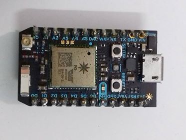
![]()
Particle Photon(both sides)
There are two buttons on the Photon: the RESET button (when holding the Photon with its USB-port to the top, it’s the button on the right) and the MODE button (on the left).
The RESET button will put the Photon in a hard reset, effectively depowering and repowering the microcontroller. This is a good way to restart the application that you’ve downloaded onto the Photon.
The MODE button serves three functions:
- Hold down the MODE button for 3 seconds to put the Photon into Smart Config mode to connect it to your local Wi-Fi network. The LED should start flashing blue.
- Hold down the MODE button for ten seconds to clear the Photon memory of Wi-Fi networks.
- Hold down the MODE button, tap once on the RESET button and wait for ten seconds** to do a Factory Reset, where the Photon is reprogrammed with the software that was installed on the Photon in the factory. The LED should turn white for three seconds and begin flashing quickly; when the LED switches to another color the Photon has been reset. This is useful if you encounter bugs with your firmware, or if you just want to get back to Tinker.
![]()
Particle Photon schematics
PINS:
The Photon has 24 pins that you can connect a circuit to. These pins are:
- VIN: To power the Photon off an unregulated power source with a voltage between 3.6V and 6V, or, if you’re powering the Photon over USB, this pin can be used as 5V V~OUT~ to power external components. In this case consider the current limitation imposed by your USB power source (e.g. max. 500mA for standard USB 2.0 ports). Avoid powering the Photon via USB and V~IN~ concurrently.
- 3V3: This pin will output a regulated 3.3V power rail that can be used to power any components outside the Photon. (Also, if you have your own 3.3V regulated power source, you can plug it in here to power the Photon).
- 3V3: This is a separate low-noise regulated 3.3V power rail designed for analog circuitry that may be susceptible to noise from the digital components. If you’re using any sensitive analog sensors, power them from 3V3 instead of from 3V3.
- !RST: You can reset the Photon (same as pressing the RESET button) by connecting this pin to GND.
- GND: These pins are your ground pins.
- D0 to D7: These are the bread and butter of the Particle Photon: 8 GPIO (General Purpose Input/Output) pins. They’re labeled “D” because they are “Digital” pins, meaning they can’t read the values of analog sensors. Some of these pins have additional peripherals (SPI, JTAG, etc.) available, keep reading to find out more.
- A0 to A7: These pins are 8 more GPIO pins, to bring the total count up to 16. These pins are just like D0 to D7, but they are “Analog” pins, which means they can read the values of analog sensors (technically speaking they have an ADC peripheral). As with the Digital pins, some of these pins have additional peripherals available.
- TX and RX: These pins are for communicating over Serial/UART. TX represents the transmitting pin, and RX represents the receiving pin.
- Then there are the PWM pins i.e Pulse Width Modulation pins
- These pins that have a timer peripheral. The Photon has 8 PWM pins: A0, A1, A4, A5, A6, A7, D0 and D1.
In our project the Particle Photon is used to obtain the sensor data and process them and send to the data to cloud/mobile app (ThinkSpeak Cloud) for easy visualization
-
The Setup
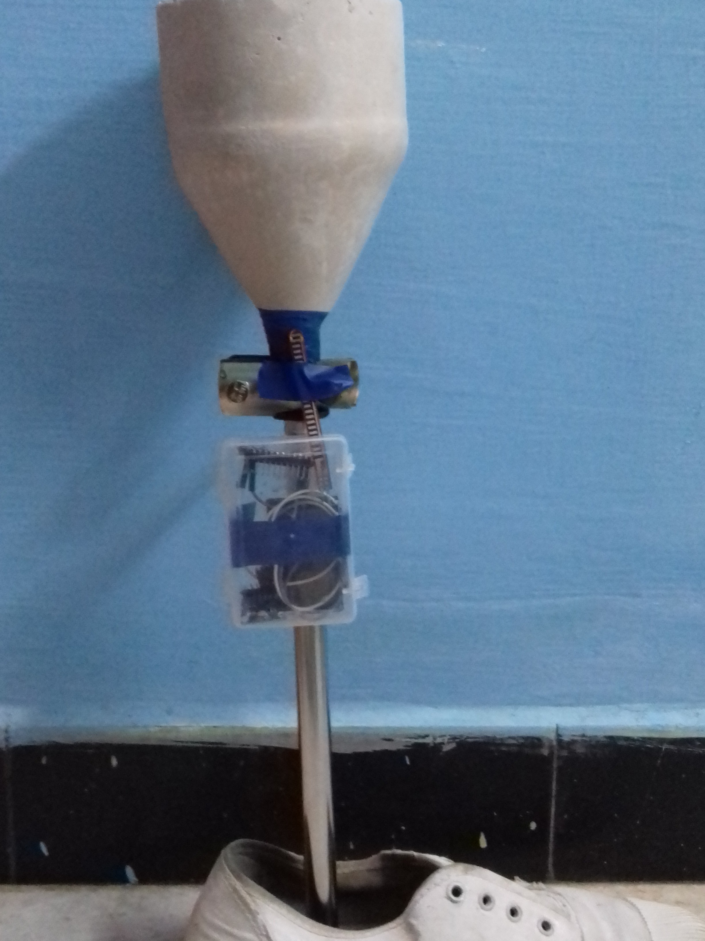
08/27/2017 at 07:23 • 0 commentsSince the design of the socket and the connector is completed, it can now be attached to complete the bionic leg. The whole setup is very simple and it consists mainly 3 parts.
- The Socket
A simple cast/mold is made from silicone rubber after measuring the dimensions of the knee region. Later we would attach a vacuum suction material so as to perfectly attach the amputated part with the bionic leg. The cost of 1kg of silicone rubber is approximately 15$.
- The Lower Leg imitator
A customized light weight stainless steel rod was designed and was fixed to the lower region of the socket and the other end being connected to a prosthetic foot/shoe. Make sure the base of the shoe is cushioned enough to withstand the stress during movements and is attached to the steel section tightly. The upper part of this is connected to the socket by means of a rotary coupler. This can be adjusted to make the leg move in desired ways. The cost of steel rod is 7$ and that of rotary coupler is 8$.
- Sensor Module
It consists of a small plastic box that incorporates particle photon, accelerometer, flex sensor and a battery. It is attached to the stainless steel rod region present in the bionic leg. The cost of photon is 20$ and the sensors are about 10$ in total.
![]()
The total cost for design is approximately equal to 60$.
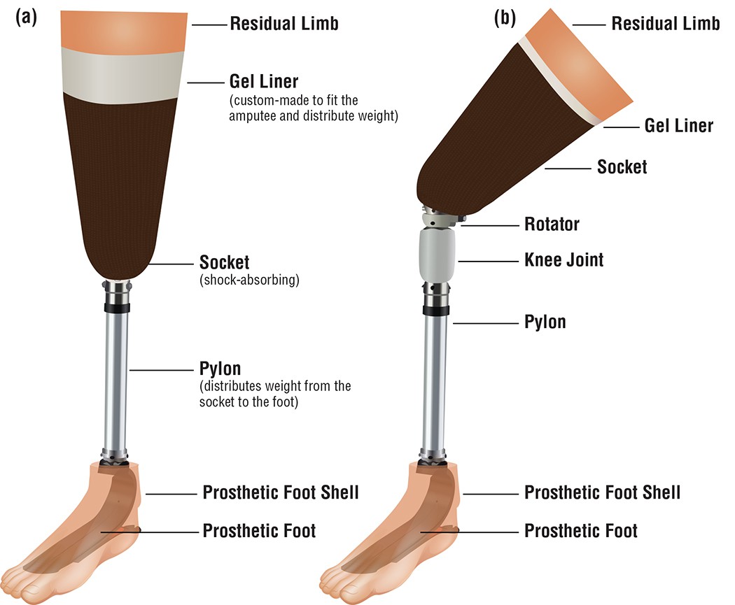
Below is an image that we expected to bring out of our design.

We obtained a similar kind of model and will be updating this with improvements and ways to reduce the cost further.
![]()
-
Design of Connector between the amputated part and foot
08/24/2017 at 17:30 • 0 commentsIn the previous log I had mentioned about the design of the mold for housing the amputated knee region. This mold has to be connected to the foot by some means. There are several parts available in the market which can perform this function. But one thing to be focused is that it should be strong enough to balance the whole weight of the body without any deformity. It should also be light in weight such that the athlete should not feel any kind of stress during action i.e: It should be a mirror image of the other leg with similar weight and must function with ease.
Why Stainless Steel? Why not Carbon Fibre?
Of course carbon fibre is comparatively better material than stainless steel.
- Carbon fiber is approximately 5 times lighter than typical stainless steel material 1.5 times .
- Carbon fiber is approximately 3 times stronger than typical stainless steel material.
- Carbon fiber is nearly 15 times greater than the cost of stainless steel.
By using the carbon fiber one may reduce the weight of whole structure but will fail in giving balance to the body having right weight proportion as the same weight of tibia.
Aluminium may be considered as it is 3 times lighter than stainless steel but it is not strong enough as in case of stainless steel.
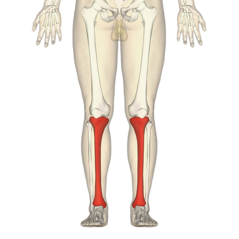
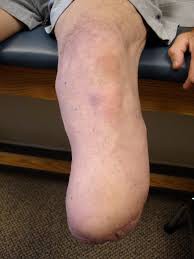
Since the main aim of developing a bionic/prosthetic replacement for the amputated part we must consider the fact it is going to replace the lower leg or Tibia and Fibula portions in the body. Of these, Tibia is the weight bearing portion. Fibula is also an equally important portion (lighter in weight) that gives support to the tibia and provides support especially in the foot region. But mimicking the tibia would alone be enough along with some couplers to design the supporting portion.
![]()
Design and Implementation
Keeping the above stated factors in mind we considered that physical features of 20 year old disabled athlete of weight 65 kg and height 180 cm. Based on the height and weight features we have designed a custom steel rod.
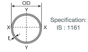
We have used the below mentioned industrial grade hollow steel section for greater efficiency and enhanced properties.
![]()
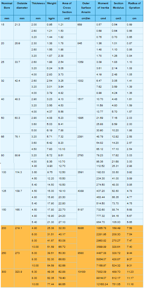
Some of the commonly used hollow steel section produced in industries and their properties are listed below.
![]()
Rotary Coupling
This plays a important role in the bionic leg movements. The fact is that it should be able to convert the impulses into work by moving the pylon(weight distribution part from mold to leg) in accordance with the amputated part. We are measuring the movements of the other leg by using sensors and using the same values the bionic leg would be used to train and one could adjust the nob according to their wish.
![]()

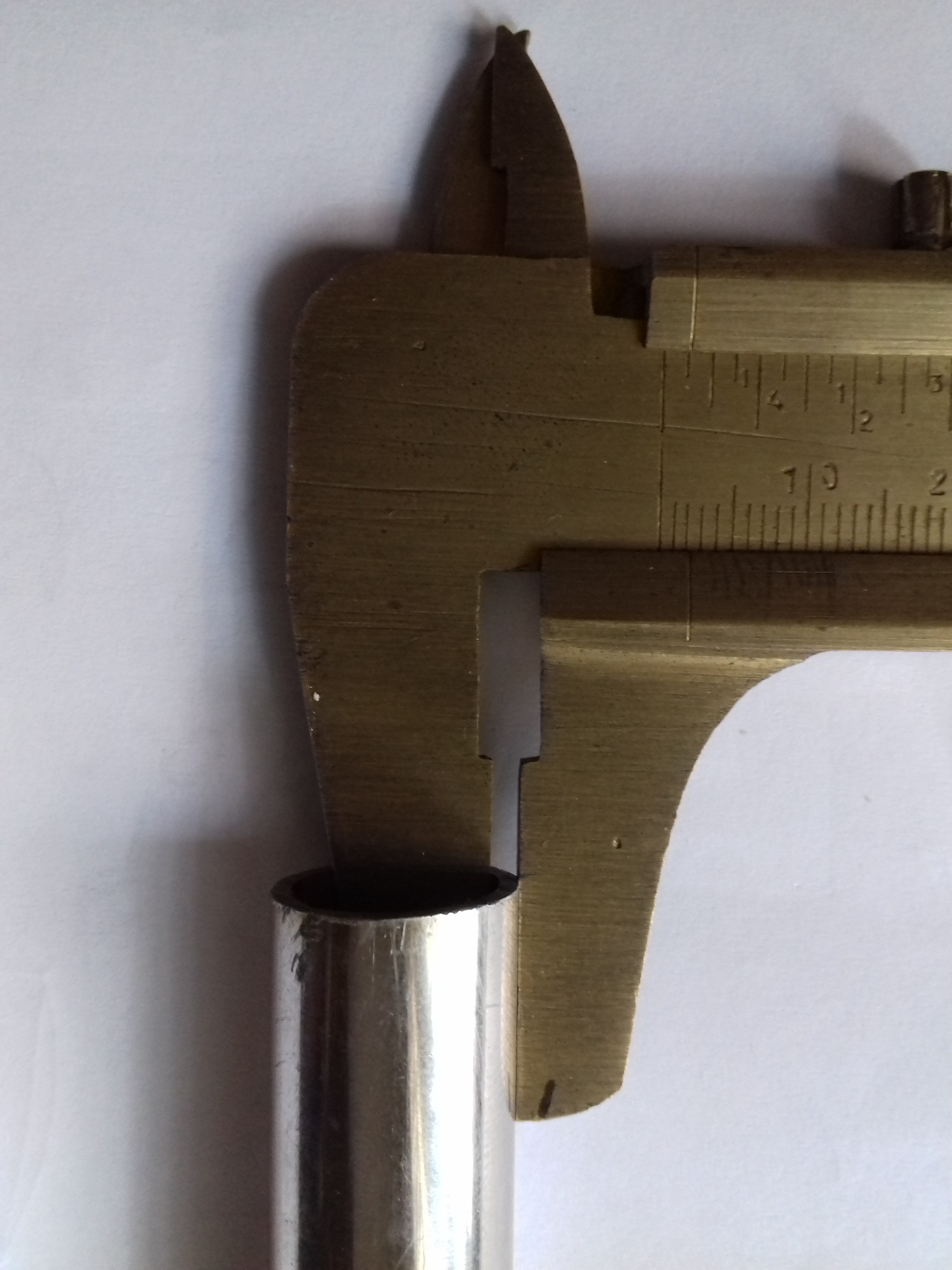
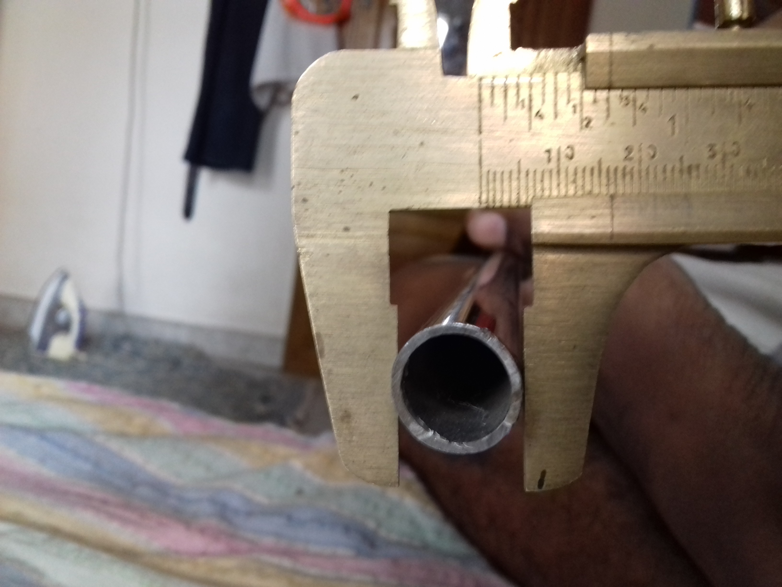
We used a vernier caliper to measure, so that it becomes precise. The hollow stainless steel section that we have ordered a steel section of
- Length 310 mm(31 cm)
- Thickness is about 1.5 mm
- Outer diameter - 16 mm.
- Area of cross section - 0.68 sq.cm
- Weight - 0.51 kg
- Maximum bearable weight - 500 kg
![]()
![]()
![]()
The other end could be connected to a prosthetic foot or shoe to complete the whole system.
-
Preparing the Socket for housing the knee region
08/22/2017 at 17:17 • 0 commentsThis mould is the special material to house the amputated knee or simply it acts as a major connection between knee and the foot. Many prosthetics that have been in the market lately have used carbon fibre as the base. Although carbon fibre is strong the major factor to be considered is that the prosthetic should not be an added weight which may result in excessive stress during movements. It should be light and must satisfy the criteria it is essentially strong to withstand the weight of the whole body. You can even 3D print the mould but that's gonna cost atleast 35$! If you would still like to 3D print the module I have attached the STL file and you could make some modifications and 3D print the mould.
You can even check out in this website http://3dprintingpricecheck.com/
![]()
Why silicone rubber?
The mould for housing the knee region can be made from any material keeping in mind the important factor- it doesn't deform in size or shape and is able to withstand the thrust of the athlete. Some of them that are used are mostly in the form of carbon fiber polymer. Carbon fibre polymers are of high cost but with great properties. Since we decided to develop the whole prototype within 50$ we founded an alternative in the form of Silicone Rubber.
It is far cheaper than other materials and has almost similar properties to that of the carbon fiber and that makes it as the best choice. Silicone rubber is an elastomer (rubber-like material) composed of silicone—itself a polymer—containing silicon together with carbon, hydrogen, and oxygen. Silicone rubbers are widely used in industry, and there are multiple formulations. Silicone rubbers are often one- or two-part polymers, and may contain fillers to improve properties or reduce cost. Silicone rubber is generally non-reactive, stable, and resistant to extreme environments and temperatures from -55 °C to +300 °C while still maintaining its useful properties. Due to these properties and its ease of manufacturing and shaping, silicone rubber can be found in a wide variety of products, including: automotive applications; cooking, baking, and food storage products; apparel such as undergarments, sportswear, and footwear; electronics; medical devices and implants; and in home repair and hardware with products such as silicone sealants. To see the full properties of Silicon Rubber Polymer
https://www.azom.com/properties.aspx?ArticleID=920
We used this silicone rubber mould making material from amazon http://www.amazon.in/MoldSil-15-Mold-Making-Silicon/dp/B06WGMCSSZ?tag=googinhydr18418-21
![]()
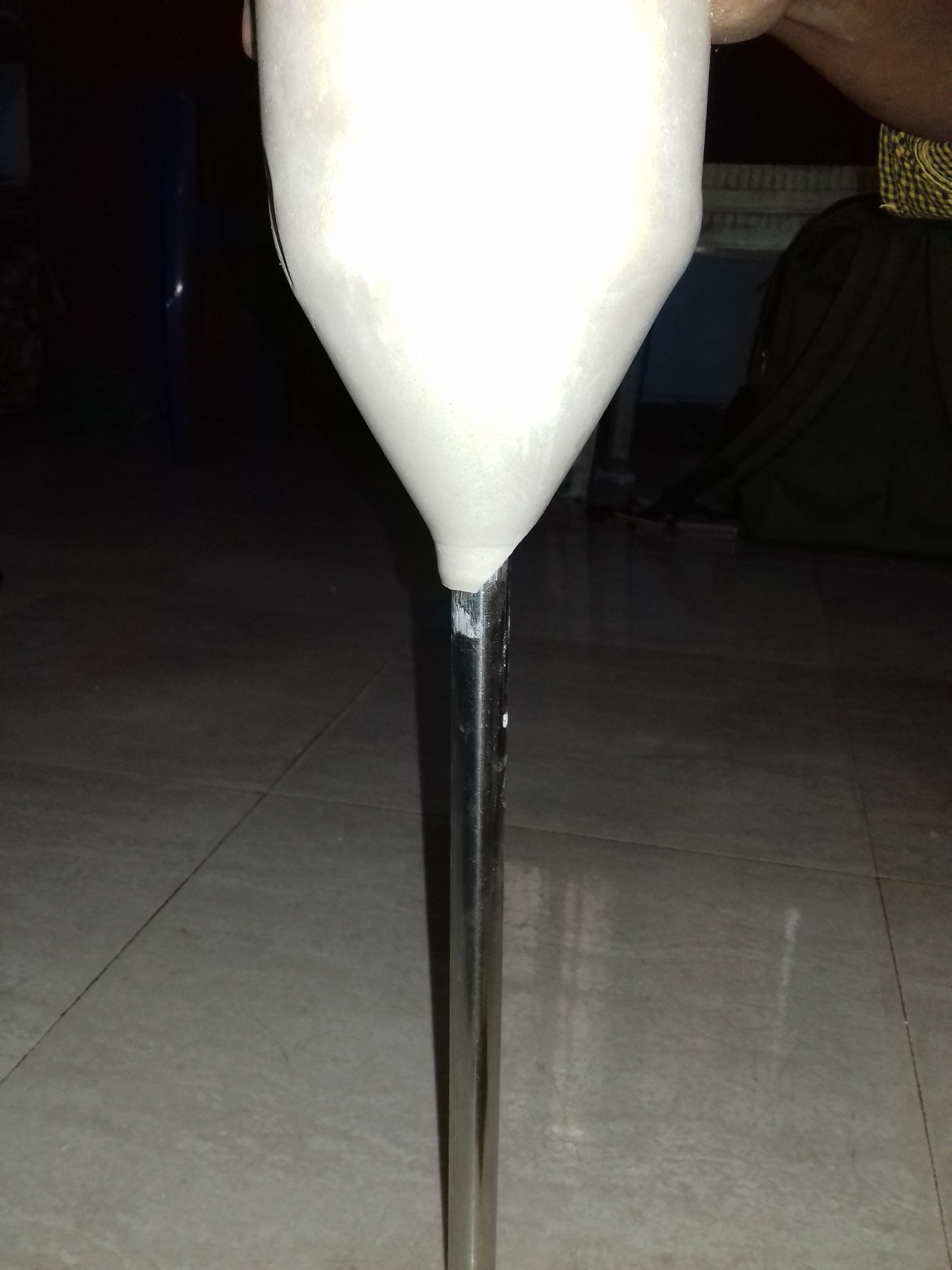
We used water bottle as the base to make the mould and and a solid to make the mould hollow. The process is so simple and could be done within minutes. It takes few hours for the liquid to turn into a perfect solid resulting in Silicon Rubber. Before it dries up attach one end of the laces preferably velcro in the mould so that we could tie the bionic leg to our thigh region.
While making mould make sure to measure the diameter of knee and add few millimeters for placing the cushiony material. The dimensions of the mould that we made has a radius of 5cm, height of 10cm, volume of 215 cub.cm and a surface area of 36 sq.cm. Make sure that the mould is completely dried up so that it retains its properties. Drill up a hole underneath the mould so as to place the stainless steel rod. In the hollow region of the mould place some cotton material that acts as a cushion.
![]()
Further we would be adding an adjustable vacuum suction part such that it becomes easy for the athlete to attach the amputated region to the socket easily!
Économique Bionic Leg System
The project emphasizes on providing value for money by using a bionic leg for sprinters embedded with smart monitoring system.

 Flex sensor circuit
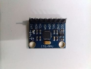
 ADXL 335 circuit diagram