Close
0%
0%

High Altitude Balloon - Phonenix 1

Design and build a high altitude balloon

Similar projects worth following
After the Eclipse of November 2012, I decided that I needed to embark on a long-term, challenging project. Since my interest is in space I decided to put some my skills and endurance to the test to design/build a High Altitude Balloon payload. There continue to be many challenges and what seem like insurmountable setbacks, but this occasions provide the greatest opportunity to learn and excel.

Aim of the Project

The aim of this project is to send a custom made payload 27km up into the Stratosphere and then recover it. The payload is to take measurements and send to the groundstation. Data to be transmitted during the flight is:-

* Air Pressure, Internal and external temperature

* System health stats

* GPS Co-Ordinates

* Photos captured by the 640x480 camera - then sends down to groundstation

Short Introduction to Hardware

Here is a quick 2 minute video introduction of the main components of this project.

What makes this project "different"

The project is a little different from other "High Altitude Balloon" (HAB) projects because I have attempted to stream key data (including images) down the wireless link to the groundstation. The Groundstation (BBB) has an inbuilt webserver and a WIFI stick, so it can act as an AccessPoint. This allows one to connect to the groundstation and view all the HAB data on a tablet or mobile phone using a web browser! One cool thing I really wanted to do (but can't at present due to budget constraints) is to pair up Google Glasses or similar to the GroundStation so that all Payload information is viewable "hands free".

A lot of work has gone to make the tracking of the balloon payload as easy as possible and to provide as much "useful" data to the user. A rich and easy to use web interface is one of these features. There are many cool things that the web interface provides. It is able to use the GPS co-ordinates of the mobile phone and the GPS co-ordinates of the HAB payload and determine the approx distance and bearing. The web interface provides alerts when certain criteria are met, e.g. no heartbeats received in the last 5 minutes, or GPS on-board has less then 4 satellites.

There has been a lot of problem solving

This project has been particularly challenging because the RFD900 modems didn't work as well as expected and so led to the creation of a new branch of the RFD900 software to include ACK functionality - https://github.com/joeman155/Sik

In addition to RFD900 difficulties, the Xmodem libraries that I used on the Ardunio had some errors that caused problems during image downloads. Some fixes were made to these.

  • 2 × RFD900 Modem A superb modem designed in Brisbanne by RFDesign. It delivers a lot of power and has a very sensitive receiver.
  • 1 × Trimble Copernicus GPS This GPS, when configured in AIR mode can allow us to gather GPS co-ordinates to an altitude of 50km
  • 1 × LinkSprite JPEG Color Camera This camera takes 640-480 stills which can be tranferred via TTL Interface.
  • 1 × Spot Messenger This provides some tracking backup services and assists in locating of payload after it has landed.
  • 1 × 2mm Copper used to create the Helix Antenna for the ground station and the Cloverleaf Antenna for the payload.

View all 14 components

  • Enhanced tracking device - a MAP

    Joseph Turner09/11/2014 at 21:42 0 comments

    The Balloon can in some cases travel quite far distances and so tracking the balloon needs to be as easy as possible. Much useful data, like GPS co-ordinates, speed and direction are already gathered. We also calculate and display the distance between the ground station and the payload. A graphical representation of the trek of the balloon and the position of the groundstation - a map - would be most helpful. This post describes the steps to accomplish this.

    OpenStreetMap (http://wiki.openstreetmap.org/wiki/OpenStreetView) is a very good "free" mapping software that can be installed on a LINUX based system. First we needed to assess this piece of software and its suitability. It was initially installed on a Debian machine using a map that encompasses a fairly large area of the Cairns region, where all balloon trajectories are within. Initial testing suggested it should meet the requirements - it was highly functional and showed the main roads that would be traveled and the API DEV interface is well documented.

    The installation process was replicated on a Beaglebone Black. Angstrom Linux was ditched in favour of Debian Linux. Additional space was required, so an 8GB microSD was inserted, formatted and mounted. I had to go through the whole slow process of compiling support for the RTC_DS3232 module and get wireless etc going. Because a lot of additional packages were required, many unrequired packages had to be removed.

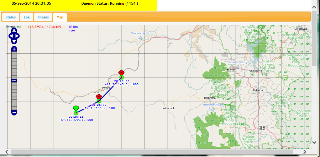
    The result, a map that can be viewed offline and show all the waypoints of the balloon and the position of the groundstation when using a phone/pad device with built-in GPS. Below is a screenshot of it.

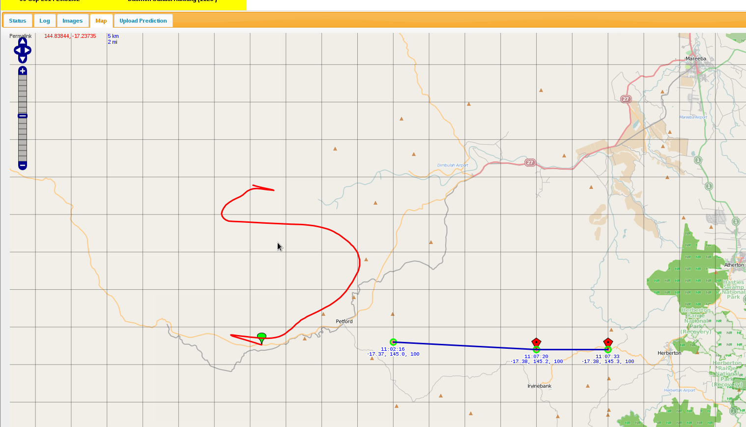
    Here is an example with predicted flight path in red.

    The interface has been written to show only way points for the current day. Red way points are for the balloon, except for the Green one which is the beginning one. A Blue point indicates the vehicle (when we have a GPS enabled device, e.g. an iPhone). Red path is the predicted flight path and can be generated by uploading a CSV file created on http://habhub.org/predict.

    NOTE: We don't have the blue icon here because this was done from a browser without a GPS device.

    A line separates each balloon way-point and time/position are recorded against each way-point.

    It can be a little slow at times, but when a map is generated and cached, when it is later recalled, things work relatively quickly. Definitely suitable for what we need it to do.

  • Radio Distance and Reliability Test 6

    Joseph Turner08/20/2014 at 10:37 0 comments

    Did an extremely successful radio test on the 4th of May from Port Douglas to Buchans Point. The distance between these two locations is 35km. With the help of my wonderful neighbour we were able to :-

    • Confirm that the radio link at 1Watt over 35 km works extremely well, even with HAB in the least optimal orientation
    • Was able to transmit an image perfectly over the 35km link without any problems at the x-modem layer.
    • Was able to get the distance between the two locations (using my mobile GPS co-ordinates and the GPS co-ordinates of the HAB)
    • The cut-down mechanism was initiated and burnt through the rubberband a little
    • Confirmed that the Groundstation new battery configuration is working well.

    The great thing about this test is that the Fresnel zone was 65% which means in the real launch, we would expect even better radio transmission results. There is no shadow of doubt that the link distance (as per rfd900 specs) of 40km is reliable and that the max link distance of 50km is probably easily achievable.

    I see no reason to continue on with other aspects of the project.

  • Gimbal for the Spot Messenger

    Joseph Turner08/20/2014 at 10:36 0 comments

    It was decided after a bit of risk analysis regarding the parachute that it would be advisable to have a gimbal arrangement to ensure that the SPOT Messenger antenna is pointing directly up at all times. This is because Spot Messengers need to be orientated correctly; and if for whatever reason the parachute did not deploy and the HAB did not maintain this orientation for sufficient time, then we may not get any measurements on its decent. [That being said, I did perform a few tests with the Spot Messenger around the wrong way and it did seem to function OK. But we cannot take chances.]

    There are several designs that can be found on various sites using hamster wheels and various ways to “attach” a spot messenger. I decided to design one from scratch.

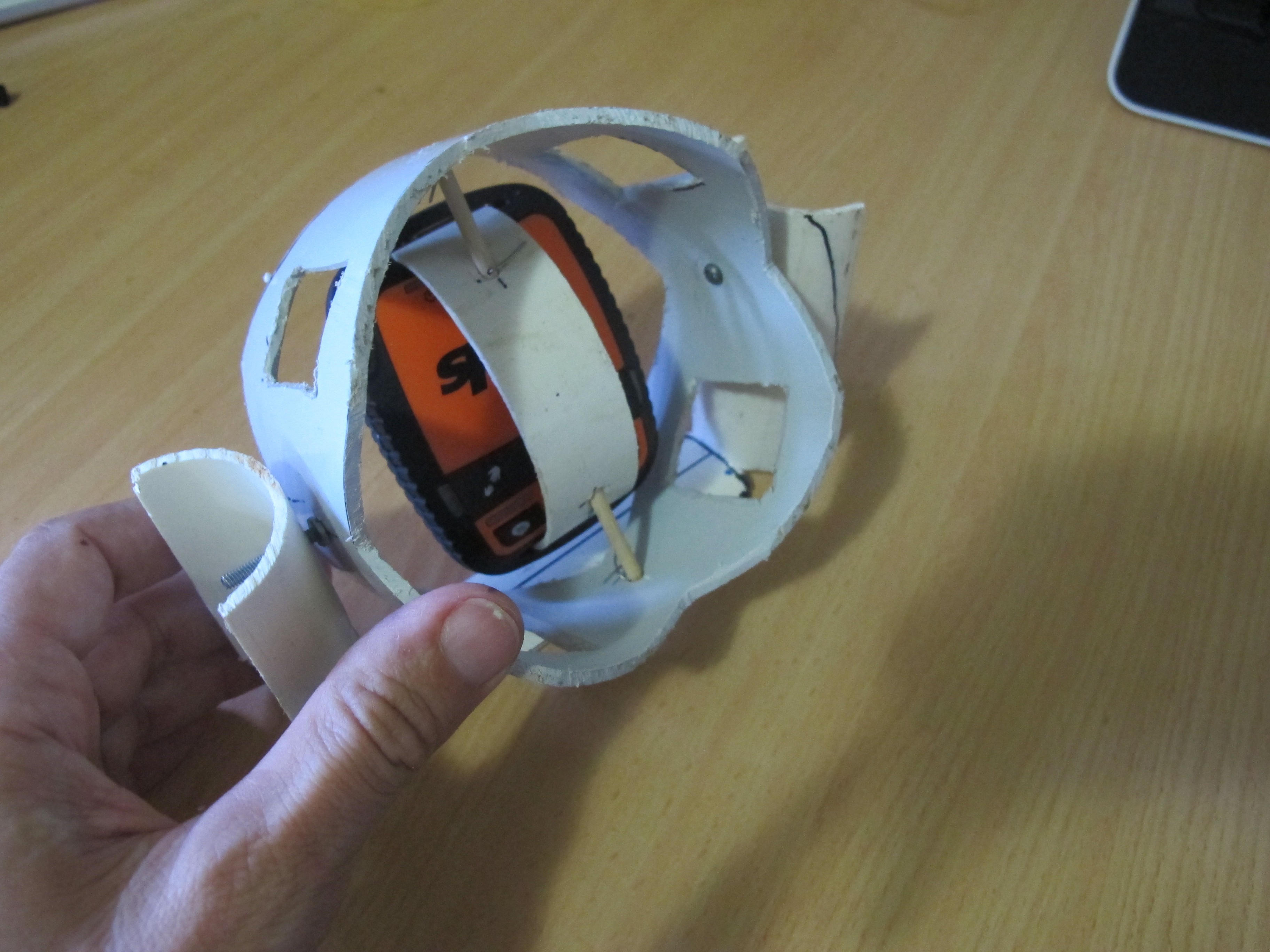
    Firstly, I got some 90mm PVC pipe and cut out a 1/3 circle segment about 20mm wide. I was able to fit this snug into the Spot Messenger III slits at each end. The 90mm PVC pipe was just the perfect thickness and the “spring” in the PVC pipe helps to keep the pipe segment “attached” to the Spot Messenger. Then a hole was drilled through this pipe segment and a skewer was passed through. This was all mounted inside a 110mm sewer PVC pipe. This 110mm sewer pipe is cut in various places to allow the easy rotation of the Spot Messenger and to reduce weight. Pieces of wire are inserted in VERY small holes drilled through the skewer to stop

    The 110mm sewer pipe segment happens to sit very neatly into a tissue box which we will use to build a fiber-glass device to allow rotation of the whole system inside the payload.

    I’ve taken a few pictures of the device and attached them below.

  • Improving the Cut-down mechanism

    Joseph Turner08/20/2014 at 10:29 0 comments

    The cut-down mechanism did not work as well as hoped during the trial launch. This post discusses the issues and proposes a possible solution.

    The problem with the cut-down mechanism

    The main problem with the cut-own mechanism is that it doesn't have sufficient power to burn a hole through balloon latex at and near the throat; at least not in a reasonable amount of time. One needs to remember that latex, being a polymer has a lot of strong chemical bonds between atoms. A lot of energy is needed to disrupt them. Also once a hole is made, there is negligible force present at the throat to open the slit to let out a decent amount of Helium gas.

    Some testing was done with "best case scenario" where we had a good 6.75volt power supply with minimal hook-up wire connected to cut-down device against thick latex, thicker than what would need to be burnt in reality, but not excessively thick. The Nichrome wire hardly made a dent against the Latex. Even after repeated attempts, we had very little to show.

    The conclusion I draw from this is that we cannot rely upon the cut-down mechanism as it stands now. Even if the latex is stretched a little, we cannot expect it to burst the balloon, or even put a hole in it. A different strategy or alternative cut-down design is required.

    A new approach

    We need to try and melt the balloon envelope where it is thinner and where the strain is greater. Remember that once it is melted, the strain/stresses in the balloon latex envelope are what help to make the hole greater. In the absence of any strain/stresses (near and at the throat of the balloon), there is little chance in the growth of the hole.

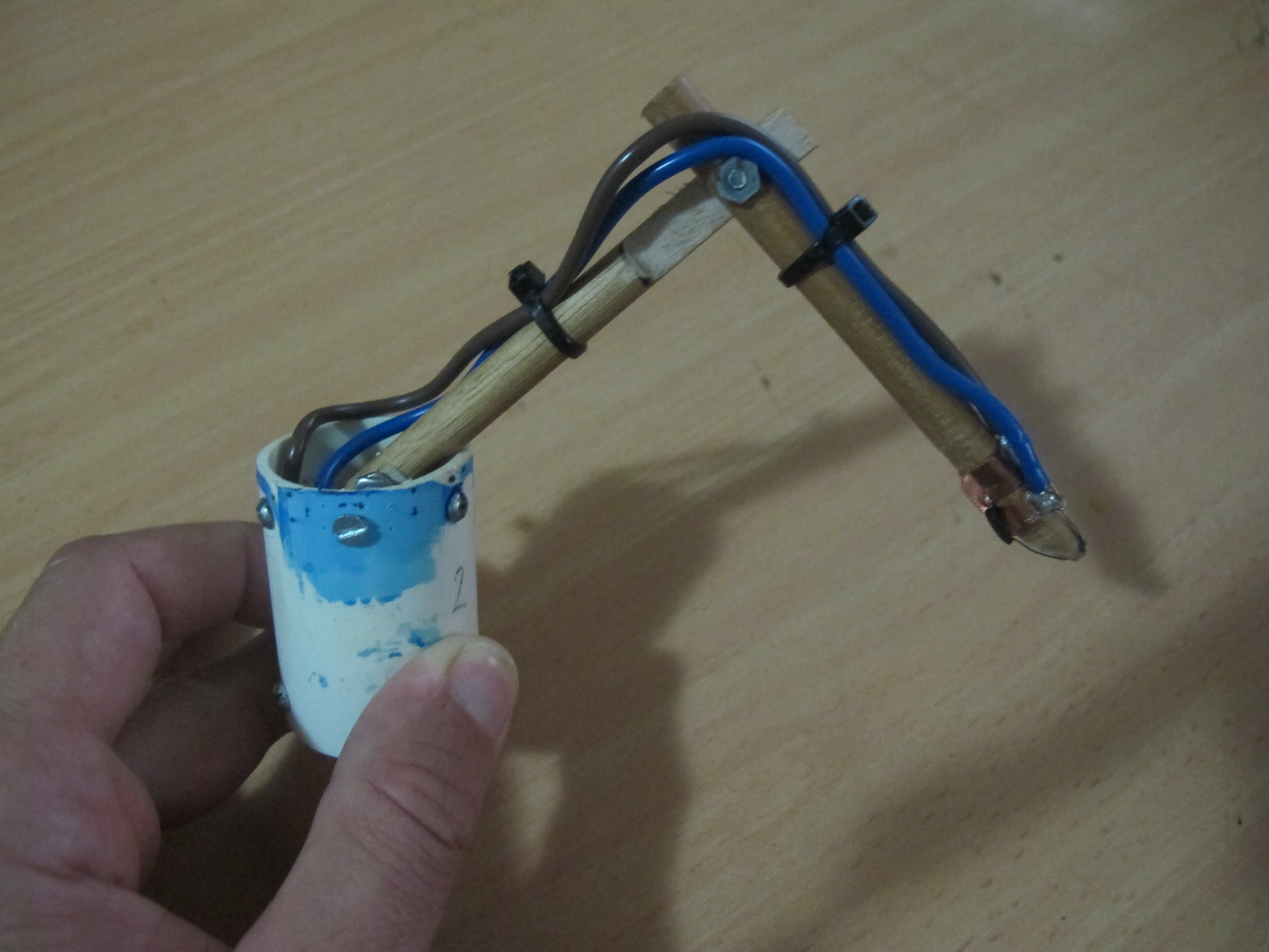
    Below is a picture of a proposed system (still yet to be completed). Its segment arm is "spring" loaded so that it should rest against the interior of the balloon surface. At the pointy end is some nichrome wire to burst the balloon.

    We will be inflating another balloon with air this time and simulating a cut-down.

  • HackHD Camera

    Joseph Turner08/20/2014 at 10:26 0 comments

    Our original HackHD camera is no longer functional. We have been forced to explore improvements to the setup to ensure whatever caused its demise won't cause it again.

    The HackHD camera is a cost-effective light camera chosen for the mission. It does have one drawback; it gets extremely hot during operation. This post identifies the issues this poses and puts forward a possible solutions to _try_ and mitigate these issues.

    The Problem

    As the payload ascends, it will experience extreme temperatures and pressures. During the initial ascent, there will be a drop in temperature and the pressure will drop slowly. There will be a chance that the camera can cool from radiation and a little bit of convection. As the payload continues to ascend into the Stratosphere, the air pressure drops off to almost zero. Convection isn’t going to work. Radiation of the heat is the only mechanism by which it can cool. There is absolutely no point having a ‘fan’ installed to cool it down because there won’t be anything to ‘blow’ on to the hot chips.

    The Solution

    We need to ensure that the HackHD can radiate heat as effectively as possible. Remember that we just want to make the HackHD last as possible. It may be close to impossible to allow it to operate the whole time. Ways to address this are:-

    1. Keep the journey as short as possible up in the Stratosphere

    2. Take video for a few minutes, then turn off to allow it to cool down, then turn it back on again. Or alternatively, take photos instead of video

    3. Add heat-sink to transfer heat away, to increase area of surface radiating heat. The flow of heat is directly proportional to the surface area of the object.

    The heat Sink

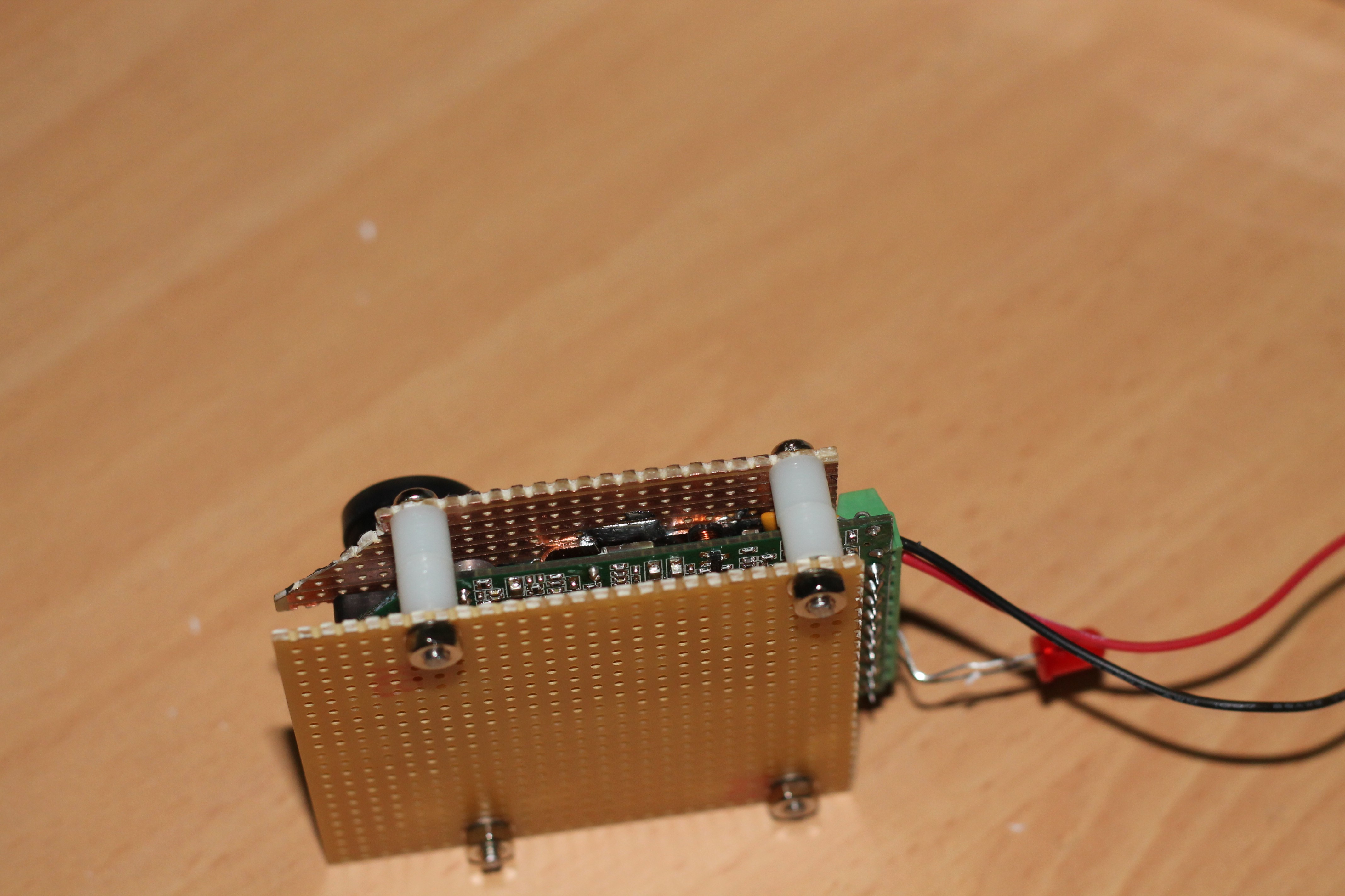
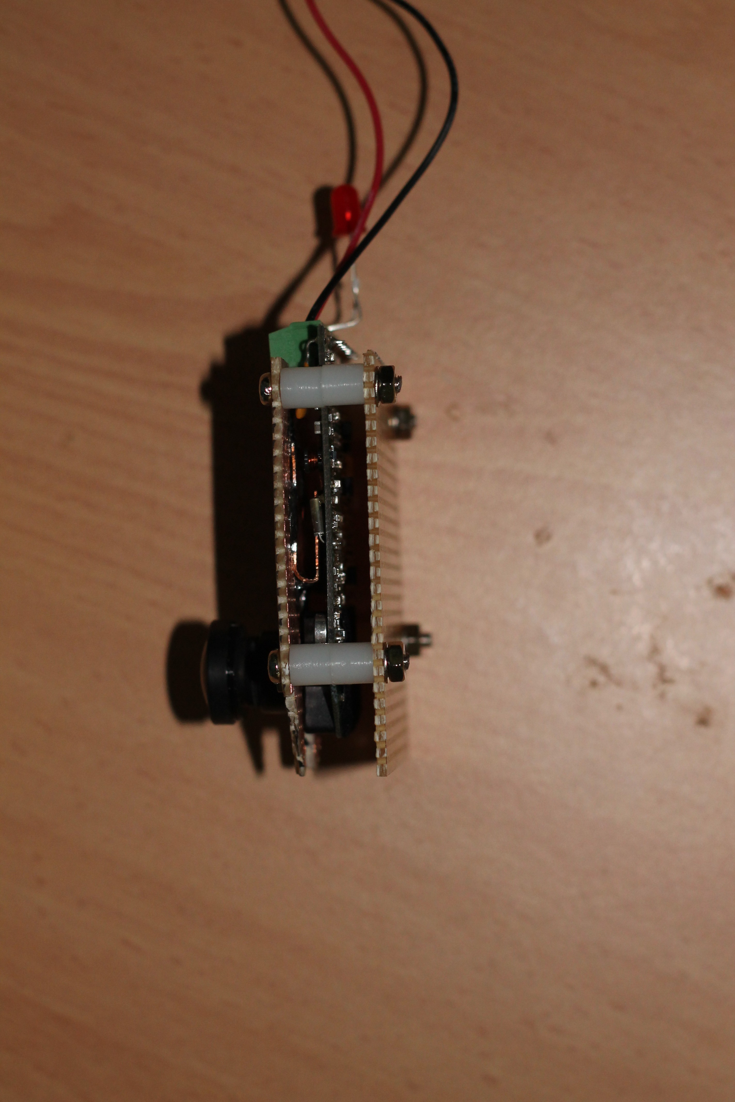
    Below are some pictures of the device that ‘hugs’ the HackHD camera and "presses" copper plate against the three hot chips.

View all 5 project logs

  • 1
    Step 1

    There are many components within this project, each requiring a fair amount of build time. High level list of steps is below:-

    Preparation

    • Acquire Parts

    Programming

    • Load appropriate firmware on to RFD900 modems
    • Load latest code into Payload Arduino
    • Load latest OS image into the Ground Station Beaglebone Black
    • Obtain latest code onto the Ground Station Beaglebone Black

    Constructing Components for the Payload

    • Construct Payload Cloverleaf antenna
    • Test Antenna with SWR meter
    • Create all Payload PCBS and solder all components
    • Assemble Electronics Box for Payload
    • Create cables
    • Create external PCB
    • Create HackHD enclosure
    • Create PVC Gimbal for the Spot Messenger
    • Create Cloverleaf antenna enclosure
    • Create waterproof external temperature module
    • Create all necessary cables
    • Assemble all the components into the payload box

    Constructing Components for the Groundstation

    • Create all Payload PCBS and solder all components
    • Create all necessary cables
    • Assemble all components into the GroundStation polycarbonate box
    • Create the Helix Antenna
    • Test Antenna with SWR meter
    • Fix Groundstation polycatbonate box on to the back of the Antenna and connect to Antenna

View all instructions

Enjoy this project?

Share

Discussions

Similar Projects

Does this project spark your interest?

Become a member to follow this project and never miss any updates