 davedarko
-
Deauther ordeal
08/24/2020 at 19:12 • 0 commentsI finally found my 2017 modified version of the deauther and added it to the download section. Use at own risk, don't come to me or Spacehuhn for advice. This is as is. Use it on your own tech only. Don't make people hate you because you want to "jam" your neighbors. Be nice and responsible.
Proud of the added "scan" for the button IO expander, as I've used different versions with different addresses over time.
-
good vibrations
08/22/2019 at 17:50 • 0 comments![]()
![]()
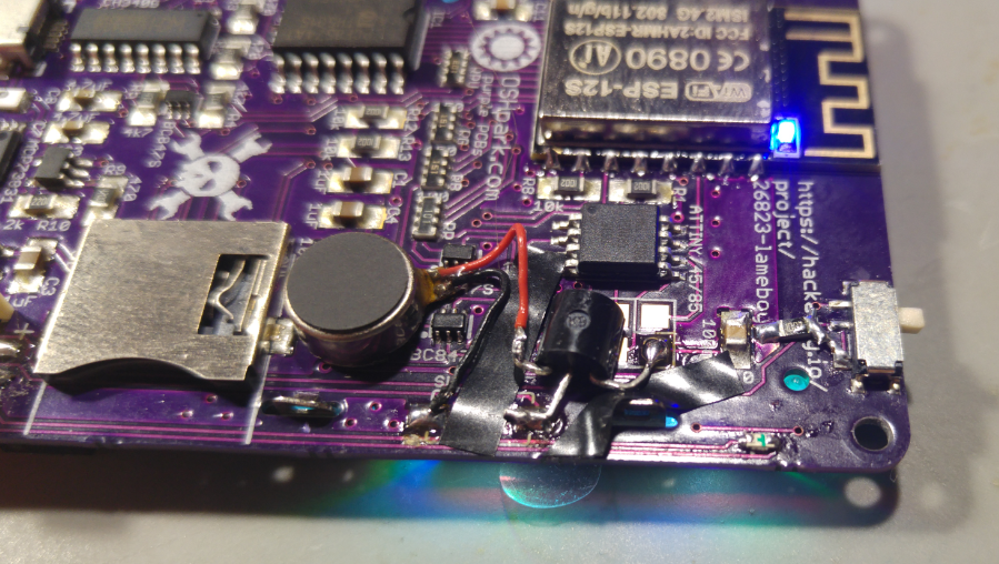
Added minimal changes overall, but they are quite a decent change functionality wise. When woody added a pager [here], I was amazed by the idea. When I saw him and his Lameboy the other day at the 3rd Hardware Happy Hour in Berlin, I decided to add that to one of my own and add an update to the schematics.
Much often I forget to add sound to my projects and here I try to free GPIO0 from resetting the LCD and instead connect a tiny buzzer to it. The LCD has a reset circuit added now.
I'm undecided to wheather I should order these versions or mod the other 10+ pcbs though, so I'll just update the github repo for now.
![]()
-
LameBoy MQTT pager aka LameQuix [by @woodworker]
03/17/2018 at 23:52 • 5 comments![]()
The Idea
I've wanted to build myself a small MQTT based message reader like those majestic 90s pagers everybody lusted after back then and I have a Lameboy.
So I knew what i had to do.This "mod" does consist of 2 parts, a little hardware upgrade and a very small firmware.
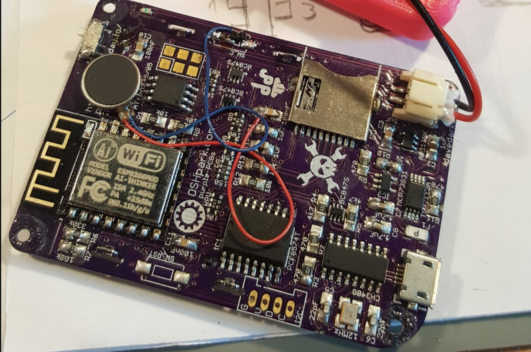
---------- more ----------The Hardware
![]()
All we need is an NPN-transistor and a small vibration motor (+ something to glue it to the Lameboy)
The Lameboy has 2 visible Action Buttons, the A and B button. But there is also a C button hidden on the backside/inside of your little Lameboy and thanks
to the magic of the I/O expander used, this button will be an OUTPUT!!!!We add an NPN Transistor with its base connected to the C-Button pad, collector to 3.3V and the emitter to the positive side of our vibration motor. And the negative side of the motor we just solder to ground.
The Software
/**
 *  _                           ____        _
 * | |                         / __ \      (_)
 * | |     __ _ _ __ ___   ___| |  | |_   _ ___  __
 * | |    / _` | '_ ` _ \ / _ \ |  | | | | | \ \/ /
 * | |___| (_| | | | | | |  __/ |__| | |_| | |>  <
 * |______\__,_|_| |_| |_|\___|\___\_\\__,_|_/_/\_\
 */

#include <ESP8266WiFi.h>
#include <SPI.h>
#include <Adafruit_GFX.h>
#include <Adafruit_PCD8544.h>
#include <Wire.h>
#include <PubSubClient.h>

uint32_t bat = 4200;
Adafruit_PCD8544 display = Adafruit_PCD8544(2, 15, 0);

#define BUTTON_UP    B10000000
#define BUTTON_DOWN  B00100000
#define BUTTON_LEFT  B01000000
#define BUTTON_RIGHT B00010000
#define BUTTON_B     B00000100
#define BUTTON_A     B00001000
#define BUTTON_SD    B00000010

#define MESSAGE_LENGTH    100
#define MAX_MESSAGES        4

boolean bottonU_pressed = false;
boolean bottonD_pressed = false;
boolean bottonL_pressed = false;
boolean bottonR_pressed = false;
boolean bottonA_pressed = false;
boolean bottonB_pressed = false;
boolean bottonSD_pressed = false;

boolean bottonU_last_pressed = false;
boolean bottonD_last_pressed = false;
boolean bottonL_last_pressed = false;
boolean bottonR_last_pressed = false;
boolean bottonA_last_pressed = false;
boolean bottonB_last_pressed = false;
boolean bottonSD_last_pressed = false;

boolean bottonU_changed = false;
boolean bottonD_changed = false;
boolean bottonL_changed = false;
boolean bottonR_changed = false;
boolean bottonA_changed = false;
boolean bottonB_changed = false;
boolean bottonSD_changed = false;

const char* ssid = "YOUR_SSID";
const char* password = "YOUR_WIFI_PASSWORD";
const char* mqtt_server = "your.mqtt.server";

const char* readChannel = "inTopic";
const char* writeChannel = "outTopic";

WiFiClient espClient;
PubSubClient client(espClient);

char msg[100];

long lastMsg = 0;
int showMessage = 0;
int messageCount = 0;
char lastmsg[MAX_MESSAGES][MESSAGE_LENGTH];

bool hasMessage = false;
bool hasRead = true;

int value = 0;

void setup()
{
  Serial.begin(115200);
  Wire.begin();

  Wire.beginTransmission(0x38);
  Wire.write(B11111110);
  Wire.endTransmission();

  setBackgroundColor('c', 200,200,200);

  display.begin();
  display.clearDisplay();
  display.setRotation(2);
  display.setContrast(58);
  display.display();

  setBackgroundColor('n', 255, 100, 100);
  display.clearDisplay();
  display.setCursor(0, 0);
  display.setTextSize(2);
  display.setTextColor(BLACK);
  display.println("OH HI!");
  display.display();
  delay(2000);

  display.setTextColor(BLACK, WHITE);
  display.setTextSize(1);

  setup_wifi();

  client.setServer(mqtt_server, 1883);
  client.setCallback(callback);
}

void setup_wifi() {
  delay(10);
  // We start by connecting to a WiFi network
  Serial.println();
  Serial.print("Connecting to ");
  Serial.println(ssid);

  WiFi.begin(ssid, password);

  while (WiFi.status() != WL_CONNECTED) {
    delay(500);
    Serial.print(".");
  }

  Serial.println("");
  Serial.println("WiFi connected");
  Serial.println("IP address: ");
  Serial.println(WiFi.localIP());
}

void callback(char* topic, byte* payload, unsigned int length) {
  Serial.print("Message arrived [");
  Serial.print(topic);
  Serial.print("] ");

  if (messageCount < MAX_MESSAGES) {
    messageCount++;
  }

  ///// lastmsg buffer change
  for (int k = MAX_MESSAGES - 1; k > 0; k--) {
    for(int l = 0; l < MESSAGE_LENGTH; l++) {
      lastmsg[k][l] = lastmsg[k-1][l];
    }
  }

  for(int j = 0; j < MESSAGE_LENGTH; j++) {
    lastmsg[0][j] = NULL;
  }

  for (int i = 0; i < length; i++) {
    Serial.print((char)payload[i]);
    if (i < MESSAGE_LENGTH) {
      lastmsg[0][i] = (char)payload[i];
    }
  }
  hasMessage = true;
  hasRead = false;
  showMessage = 0;
  Serial.println();
}

void reconnect() {
  // Loop until we're reconnected
  while (!client.connected()) {
    Serial.print("Attempting MQTT connection...");
    // Attempt to connect
    if (client.connect("ESP8266Client")) {
      Serial.println("connected");
      // Once connected, publish an announcement...
      client.publish(writeChannel, "hello world");
      // ... and resubscribe
      client.subscribe(readChannel);
    } else {
      Serial.print("failed, rc=");
      Serial.print(client.state());
      Serial.println(" try again in 5 seconds");
      // Wait 5 seconds before retrying
      delay(5000);
    }
  }
}

void loop()
{
  read_buttons();

  display.clearDisplay();

  // show selected message
  display.print("Msg #");
  display.print((showMessage + 1));
  display.print("/");
  display.print(messageCount);

  // show battery voltage
  uint32_t aIn = analogRead(A0);
  aIn = map(aIn, 0, 1024, 0, 4400);
  bat = (aIn+bat)/2;
  display.print("  ");
  display.println(bat);

  if (!client.connected()) {
    reconnect();
  }
  client.loop();

  // print selected message
  display.print(lastmsg[showMessage]);
  display.println("");

  // backlight on in case of unread message
  if (hasRead) {
    setBackgroundColor('n', 0, 0, 0);
  } else {
    setBackgroundColor('n', 255, 100, 100);
  }

  // notify for new message
  if (hasMessage) {
    vibrate(200);
    hasMessage = false;
  }

  // scroll messages down
  if (bottonD_pressed && bottonD_changed) {
    if (showMessage < ( MAX_MESSAGES - 1) ) {
      showMessage++;
    }
  }

  // scroll messages up
  if (bottonU_pressed && bottonU_changed) {
    if (showMessage > 0) {
      showMessage--;
    }
  }

  // mark message read
  if (bottonB_pressed) {
    if (showMessage == 0) {
      hasRead = true;
    }
  }

  // send message
  if (bottonA_pressed && bottonA_changed) {
    ++value;
    snprintf (msg, 75, "hello world #%ld", value);
    Serial.print("Publish message: ");
    Serial.println(msg);
    client.publish(writeChannel, msg);
    vibrate(100);
  }

  display.display();
  delay(100);
}

void vibrate(int milli) {
    Wire.beginTransmission(0x38);
    Wire.write(B11111111);
    Wire.endTransmission();

    delay (milli);

    Wire.beginTransmission(0x38);
    Wire.write(B11111110);
    Wire.endTransmission();
}

void setBackgroundColor(char c, int r, int g, int b)
{
  // c is fade to color, n is now color
  Wire.beginTransmission(0x80);
  Wire.write(c);
  Wire.write(r);
  Wire.write(g);
  Wire.write(b);
  Wire.endTransmission();
}

void read_buttons()
{
  Wire.requestFrom(0x38, 1);
  byte data = Wire.read();
  bottonU_pressed = (~data & BUTTON_UP) > 0;
  bottonD_pressed = (~data & BUTTON_DOWN) > 0;
  bottonL_pressed = (~data & BUTTON_LEFT) > 0;
  bottonR_pressed = (~data & BUTTON_RIGHT) > 0;
  bottonA_pressed = (~data & BUTTON_A) > 0;
  bottonB_pressed = (~data & BUTTON_B) > 0;
  bottonSD_pressed = (~data & BUTTON_SD) > 0;

  bottonU_changed = bottonU_last_pressed != bottonU_pressed;
  bottonD_changed = bottonD_last_pressed != bottonD_pressed;
  bottonL_changed = bottonL_last_pressed != bottonL_pressed;
  bottonR_changed = bottonR_last_pressed != bottonR_pressed;
  bottonA_changed = bottonA_last_pressed != bottonA_pressed;
  bottonB_changed = bottonB_last_pressed != bottonB_pressed;
  bottonSD_changed = bottonSD_last_pressed != bottonSD_pressed;

  bottonU_last_pressed = bottonU_pressed;
  bottonD_last_pressed = bottonD_pressed;
  bottonL_last_pressed = bottonL_pressed;
  bottonR_last_pressed = bottonR_pressed;
  bottonA_last_pressed = bottonA_pressed;
  bottonB_last_pressed = bottonB_pressed;
  bottonSD_last_pressed = bottonSD_pressed;
}
Now i have my very own small and simple MQTT based pager \o/
-
Arduino skeleton script
03/14/2018 at 11:23 • 0 commentsno wifi, 4 stars.
#include <ESP8266WiFi.h> #include <SPI.h> #include <Adafruit_GFX.h> #include <Adafruit_PCD8544.h> #include <Wire.h> uint32_t bat = 4200; Adafruit_PCD8544 display = Adafruit_PCD8544(2, 15, 0); #define BUTTON_UP B10000000 #define BUTTON_DOWN B00100000 #define BUTTON_LEFT B01000000 #define BUTTON_RIGHT B00010000 #define BUTTON_A B00000100 #define BUTTON_B B00001000 #define BUTTON_C B00000001 #define BUTTON_SD B00000010 boolean bottonU_pressed = false; boolean bottonD_pressed = false; boolean bottonL_pressed = false; boolean bottonR_pressed = false; boolean bottonA_pressed = false; boolean bottonB_pressed = false; boolean bottonC_pressed = false; boolean bottonSD_pressed = false; void setup() { Serial.begin(115200); Wire.begin(); setBackgroundColor('c', 200,200,200); display.begin(); display.clearDisplay(); display.setRotation(2); display.setContrast(58); display.display(); setBackgroundColor('n', 255, 100, 100); display.clearDisplay(); display.setCursor(0, 0); display.setTextSize(2); display.setTextColor(BLACK); display.println("OH HI!"); display.display(); delay(2000); setBackgroundColor('c', 200 ,200, 200); display.setTextColor(BLACK, WHITE); display.setTextSize(1); } void loop() { read_buttons(); display.clearDisplay(); uint32_t aIn = analogRead(A0); aIn = map(aIn, 0, 1024, 0, 4400); bat = (aIn+bat)/2; display.println(bat); if (bottonU_pressed) display.println("U"); if (bottonD_pressed) display.println("D"); if (bottonL_pressed) display.println("L"); if (bottonR_pressed) display.println("R"); if (bottonA_pressed) display.println("A"); if (bottonB_pressed) display.println("B"); if (bottonC_pressed) display.println("C"); if (bottonSD_pressed) display.println("SD"); display.display(); delay(25); } void setBackgroundColor(char c, int r, int g, int b) { // c is fade to color, n is now color Wire.beginTransmission(0x80); Wire.write(c); Wire.write(r); Wire.write(g); Wire.write(b); Wire.endTransmission(); } void read_buttons() { Wire.requestFrom(0x20, 1); byte data = Wire.read(); bottonU_pressed = (~data & BUTTON_UP) > 0; bottonD_pressed = (~data & BUTTON_DOWN) > 0; bottonL_pressed = (~data & BUTTON_LEFT) > 0; bottonR_pressed = (~data & BUTTON_RIGHT) > 0; bottonA_pressed = (~data & BUTTON_A) > 0; bottonB_pressed = (~data & BUTTON_B) > 0; bottonC_pressed = (~data & BUTTON_C) > 0; bottonSD_pressed = (~data & BUTTON_SD) > 0; } -
customised spacehuhn case
02/25/2018 at 16:11 • 4 comments![]()
I've used a 3D printing pen to test if I could do some inlays with that - I think it worked out reasonably well :)
-
CircuitPython on the Lameboy
02/23/2018 at 08:25 • 0 comments![]()
Here are some commands you need to get started to install circuit python and snake on @ɖҿϝիɟթվ s #PewPew FeatherWing engine. How awesome is that :) You can also follow along Radomir's description, which is way better.
https://hackaday.io/project/21578-pewpew-featherwing/log/100304-lameboy-playing-pewpew-games
sudo esptool.py -p /dev/cu.wchusbserial1410 erase_flash sudo esptool.py -p /dev/cu.wchusbserial1410 --baud 115200 write_flash --flash_size=detect 0 adafruit-circuitpython-feather_huzzah-2.2.3.bin // deactivate esp debug to serial import esp; esp.osdebug(None) ampy -p /dev/cu.wchusbserial1420 ls ampy -p /dev/cu.wchusbserial1420 put lameboy.py ampy -p /dev/cu.wchusbserial1420 put pew.py ampy -p /dev/cu.wchusbserial1420 put snake.py ampy -p /dev/cu.wchusbserial1420 put menu.py ampy -p /dev/cu.wchusbserial1420 put main.py // in case of errors import os; os.remove('main.py') // change attiny i2c adress to allow coms import lameboy; lameboy.i2c.writeto(0, b'A\x0d\xd0\x0d\x0d') -
Changing the address of the Attiny
02/20/2018 at 21:17 • 6 comments[UPDATE] I've soldered up another Lameboy and checked the behaviour in Arduino, tried sending data to 0x0d but nothing happened. I've then set the address to 0x0d and it works with that address. Seems like it won't be written to the EEPROM on init but later checks the EEPROM for an address. (btw., I've edited the range for scanning from 1-255 to 0-127). It's probably still a different experience with python.
![]()
Thanks to Radomir @ɖҿϝիɟթվ who read through the cyz_rgb code and found the procedure, it's now possible to set the adress of the blinkM clone to a "real" legal value. This is how you'd do that in Arduino. After that it's stored into the EEPROM of the attiny. I'll do that for the next kits that go out.
void setAdress(byte a) { // A X D0 0D X Wire.beginTransmission(0x00); Wire.write('A'); Wire.write(a); Wire.write(0xd0); Wire.write(0x0d); Wire.write(a); Wire.endTransmission(); } -
R3.1 boards in the wild
02/20/2018 at 08:55 • 0 commentsSo before I started selling on @Tindie , I was sending off a kit to @ɖҿϝիɟթվ and I forgot to send him a crystal with that kit / check all the content before sending. There are also two fully assembled versions out there now, one has an ESP chip with 2MB flash instead of 4MB. From then on every ESP12 module is checked before sending.
So here's rule number one:
Use the checklist and check if every part is in the kit. Obviously.
Known issues number one is the enable pin of the power regulator is floating, you need to botch the 10k to the switch.
I will modify all future / rest of the pcbs so it's clear where to put it
- missing markings for RGB LEDs, the dot points towards the USB plug
- the charging indicator LED - minus points towards the USB plug
- power muxing chip pin 1 points AWAY from USB plug
There is no test program that greats you with a "hooray, you've made it".
flash the ESP with a basic code, flash RGB lights, check buttons and display
Change the I2C address of the attiny before shipping
to be continued...
-
the quest for sound
02/15/2018 at 11:55 • 12 commentsI'm currently looking into getting a sound pin and the most likely candidate right now is the LCD reset pin. Did anyone ever had any problems not using the reset pin of the Nokia LCD? What could I test to make sure it works fine? worst case scenario is turning the lameboy on and off again, I guess. I could try using RX and TX for sound, where depending on the TX state the RX would emit sound (no modem noises while uploading if done right). But if I could free the RST pin for sound, then I could use the same idea for RX and TX to transmit IR maybe. Would be cool features to have, I think.
Also to consider:
- using the D/C pin of the display for other things, maybe move to TX
- auto reset circuit for pin http://www.avrfreaks.net/sites/default/files/SSD1306_OLED_circuit.jpg
- maxim power on reset app note https://www.maximintegrated.com/en/app-notes/index.mvp/id/3227
![]()
-
kits
12/01/2017 at 15:23 • 4 commentsI'm slowly starting to buy parts for 12 kits. I have a list of people who are interested already and will contact them, once I have everything. It takes me longer than I would have wanted, some financial mishaps are forcing me to not spend money on that. Instead I started selling stuff on tindie, to get some money in again. I've been to a hospital in America, everything is alright, but I had to pay 3 bills upfront before I get all the money back from my insurance. This also is under control, just sucks to watch out not spending too much on stuff.
[UPDATE] seems like I only need 100 Ohm and 150 Ohm resistor arrays, but sadly I had no luck so far getting them in Germany. Only on aliexpress I found some and they usually take a long time to arrive here. No luck on eBay. Also I'm not sure I really need resistors on the green and blue LEDs anyway, since their forwarding voltage is 3.3V at 20mA.
[UPDATE] Thanks to my recent work on #ESP8266 RFid reader I've noticed that the regulator needs to be pulled low, you can't just let it float - which makes perfect sense thinking about it. So that needs to be botched with every version now, but the files are updated. For kitting things up, I need to make sure that everyone is clear on what is what and where to put it. It's complicated and frustrating for sure, hope to make it easy enough though, since selling finished ones seems not an option atm. - German laws... always complicating stuff ;)
This is probably worth watching :)
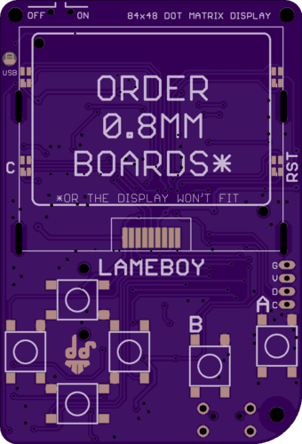
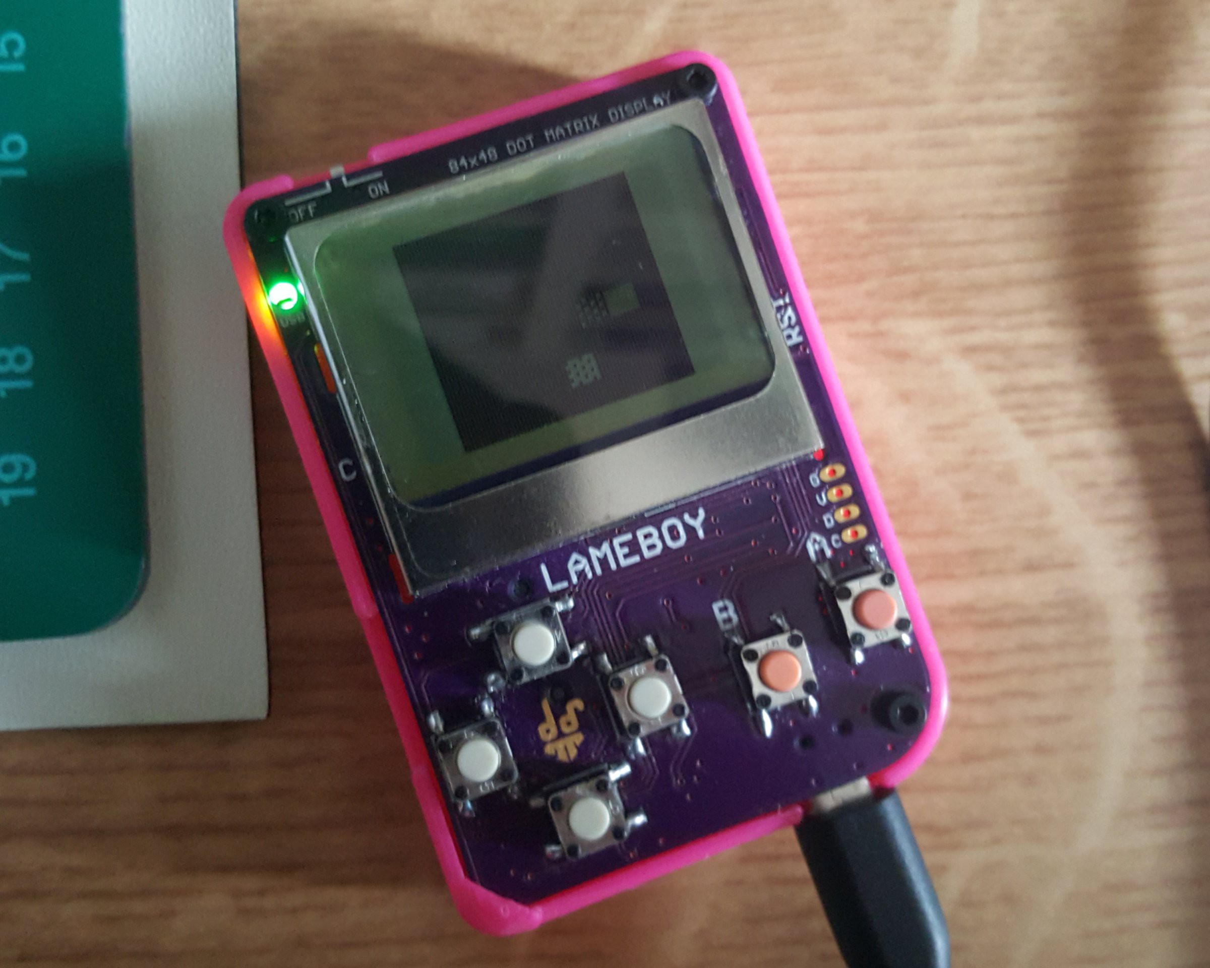
LAMEBOY - another ESP12 handheld
fully portable ESP12 project with battery charging and power muxing


