Sproket
-
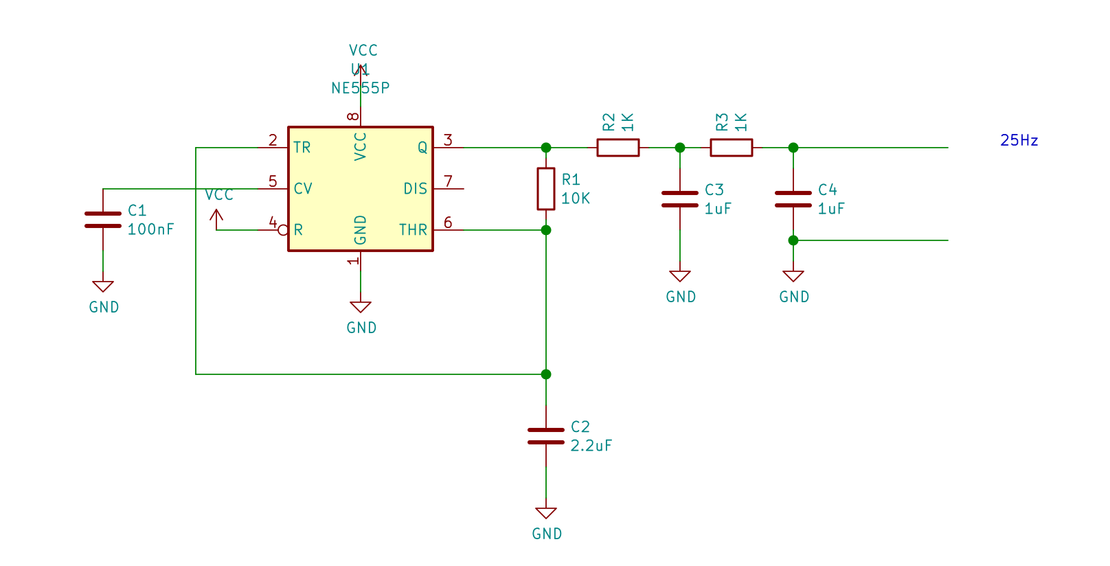
555 shaped triangle wave generator
06/17/2021 at 14:46 • 0 commentsUsing this NE555 timer circuit with an RC wave shaping output stage, it appears I have the desired generated signal. Being powered with 9V and a negligible amount of current (singular milliamps) it is running at 27Hz with a 55% duty cycle. It couldn't be much better than that.
Next task is to find out what the signal looks like with an LM386 power-amp for the ring-modulator.
![]()
-
LFO Low Frequency Oscillator ~30Hz Sine
02/03/2021 at 10:24 • 0 commentsSince this ring modulator project started I have not found an ideal solution for generating low frequency sine waves. This is particularly due to wanting a sub-audio 30Hz sine which most circuits can't quite manage. I have tried Wien bridge oscillators (with and without light bulbs), multivibrators, quadrature amplifiers, and various logic circuits.
Clean signals from a Wien bridge oscillator broke down nearer the lower frequencies and often reached the limits of being able to 'self start' reliably.
Most logic based circuits suffer from asymmetric threshold voltages which is compounded by how quickly a capacitor can discharge compared to charge.
A solution?
I may compromise and use a triangle-wave, which arguably has the same relationship with a rectifier circuit (or ring-modulator) as a sine-wave would have. Harmonics generated by a triangle-wave are not desirable as they will effect the overall sound, a solution may be to partially shape the output by adding some capacitance.
The current go-to commercial device is a Moog Minifooger MF Ring modulator, which reportedly generates a shaped triangle-wave when you select sine. So if it's good enough for the pro's...
555, anyone?
-
New transformers tested and working
12/16/2020 at 11:59 • 0 commentsThe 1:1 +C.T. transformers (Vigortronix VTX-101-1604) have arrived and seem to work well once soldered to some strip-board. Powering this board using the existing microphone amplifier and an external sine-wave source gives the desired result. It seems as though a buffer amplifier is required on the output due to signal drop through the ring modulator. Can always use that as a volume control for the speaker output. Nearly there, just being held back by another project deadline.

1:1 Ring Modulator on strip board -
Some considerations and findings
11/20/2020 at 10:42 • 0 commentsThe LT700 transformer is readily available, relatively cheap, and can be used in a ring modulator circuit. Many people including myself have used it successfully to create a Dalek / Cyberman voice changer. However, it is also less than ideal. The transformer is primarily designed to be used as an output stage for driving a speaker. Which is kinda okay for the output half of the ring modulator, however, the input half is effectively using the transformer backwards. Driving a signal into the very low impedance output of the transformer (especially with a large step-up in turns ratio) is a bit tricky. The ever popular LM386 power-amp IC is supposed to drive loads of at least 4R, unfortunately the transformers single-winding has a resistance of nearer zero (ignoring transformer load relationships for simplicity). Ideally an audio isolation transformer with a turns ratio of 1:1 should be used. From the usual retailers these can easily cost £10 GBP or $13 USD single quantity, so an online 'auction' website may be the way to go for ~half the price.
TLDR: The LT700 should be replaced with an audio isolation transformer with ratio of 1:1 so that the LM386 can drive a more suitable load.
UPDATE: I have managed to find a suitable 1:1 600R isolation transformer with a centre tap for £4 single quantity. Shall hopefully have some Vigortronix VTX-101-1604 transformers arrive next week for testing.
Shame.. I have a bag full of LT700 transformers and now don't know what to do with them.
I very quickly designed a PCB for the ring modulator using Easy EDA, unfortunately the footprint I used didn't have large plated through holes for mechanical support. This is being corrected and will be designed in KiCAD with a custom footprint as one doesn't seem to exist.

Mechanical through-holes need to be added to the next revision, but looks neat. 
Soldering is a mess due to a dirty board. The copper idents turned out nicely though. -
Microphone amplifier
11/05/2020 at 09:26 • 0 commentsAn electret microphone amplifier circuit using an LM386 has been successfully tested. With an additional capacitor between pins 1 & 8 for 200x gain, the amplified signal is a bit overkill. A potentiometer wired as a variable resistor will need to be included for setting the correct gain. This gain value could be fixed, but when using a microphone inconsistent input volume is to be expected.
Microphone amplifier schematic![]()
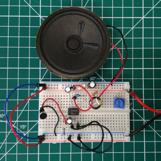
Microphone amplifier on breadboard. Using a speaker for output testing there is lots of feedback, especially when C4 200x gain capacitor is fitted.![]()
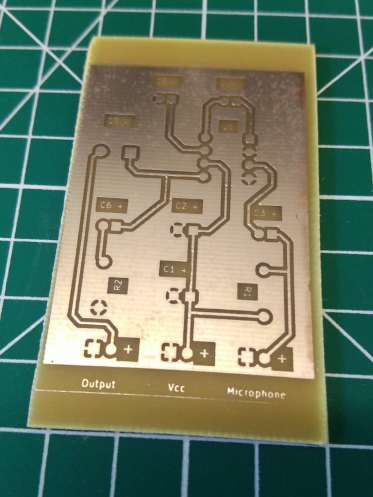
Printed Circuit Boards. This etched board shows version two of the layout with a corrected IC footprint and addition of component idents on the top copper layer. Components are on the bottom layer due to it being a single-sided PCB. Kicad can get confusing with idents being pushed to a different layer than the footprint, but it is workable.![]()
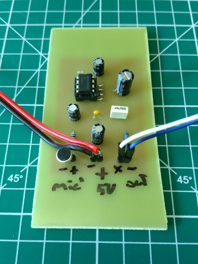
First revision of PCB. Assembled and working.![]()
-
Frequency generator
08/30/2017 at 12:55 • 0 commentsUsing an LM386 low voltage amplifier I made a simple resonator to see what the output would be. A 470uF capacitor with the load of an 8Ohm speaker gave a useful frequency of 40Hz. Unfortunately instead of resembling a sine wave the lower frequencies became more of an asymmetrical square wave. This is still usable to an extent but not ideal for recreating an authentic sound. It would be best to make a more accurate sine wave generator to drive the amplifier and ring-modulator in tern.
Direct digital synthesis of waveforms is entirely possible, cheap, flexible, and compact using a microcontroller. But since I have the transformers and amplifiers at hand, and the Radiophonic workshop wouldn't of had microcontrollers, I want this project to be entirely analogue.
![]()
-
And it begins - Documentation
08/21/2017 at 12:24 • 0 commentsAfter a lot of hassle with editing build instructions and a lot of re-uploading of images; I have the start of this projects documentation. I now have images of a couple schematics, breadboarding, and soldered vero strip board. A link has been added to the BBCs research page for the Radiophonic Workshop ring modulator, and a schematic where I found the light-organ / LED VU meter.
Other modules to come soon.
-
Document and finalise
08/19/2017 at 11:13 • 0 commentsFor a while now, since coming across a whole pile of signal transformers. I have been making various building blocks to retrofit a portable guitar amplifier as a Dalek/Cybermen voice changer.
I have all the parts working, almost. This is an attempt to document my works for the hopeful benefit to myself and others.
Dalek / Cybermen voice changer
A simple ring-modulator circuit which can change your voice to sound like a Dalek or Cybermen from Doctor Who