Vignesh Ravichandran
-
CM-01B Contact Microphone
10/10/2017 at 10:24 • 0 commentsWhile starting this project, I saw this sensor as a potential bottleneck due to my size constraints. Despite multiple failed experiments using a PVDF film (LDT0-028k) as it coupled to the knee using 3m adhesives, The signal was not too promising and the coupling method was a no go for a final prototype.
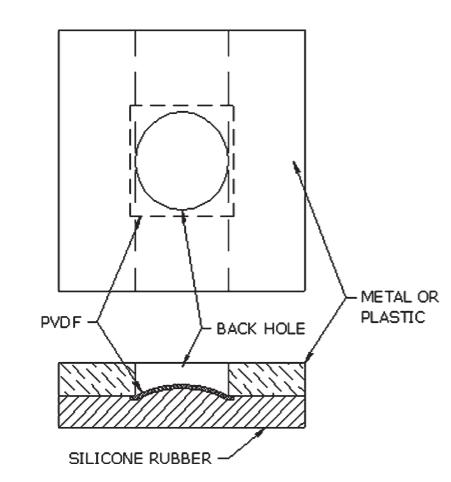
I turned my sights back to the CM-01B sensor and wanted to figure out how on earth these guys pulled it off. I had gone through the publication the makers of this magic sensor had published (Reference publication by MEAS spec)![Image result for cm-01b contact microphone]()
The tech sheet had some interesting illustration which gives some critical insights about the working of this sensor, The film in this case is stressed and kept in curved form factor.While this was quite valuable to know I decided to get a more detailed insight by doing a bit of a teardown. Despite seeming to be rather simple an innocous, The device was rather difficult to teardown. I first tried using Allen keys to get the pins out to remove the sensing element from the enclosure but I was unable to get it to work.
Then after spending hours I decided to go get the big tools out (My hand drill)
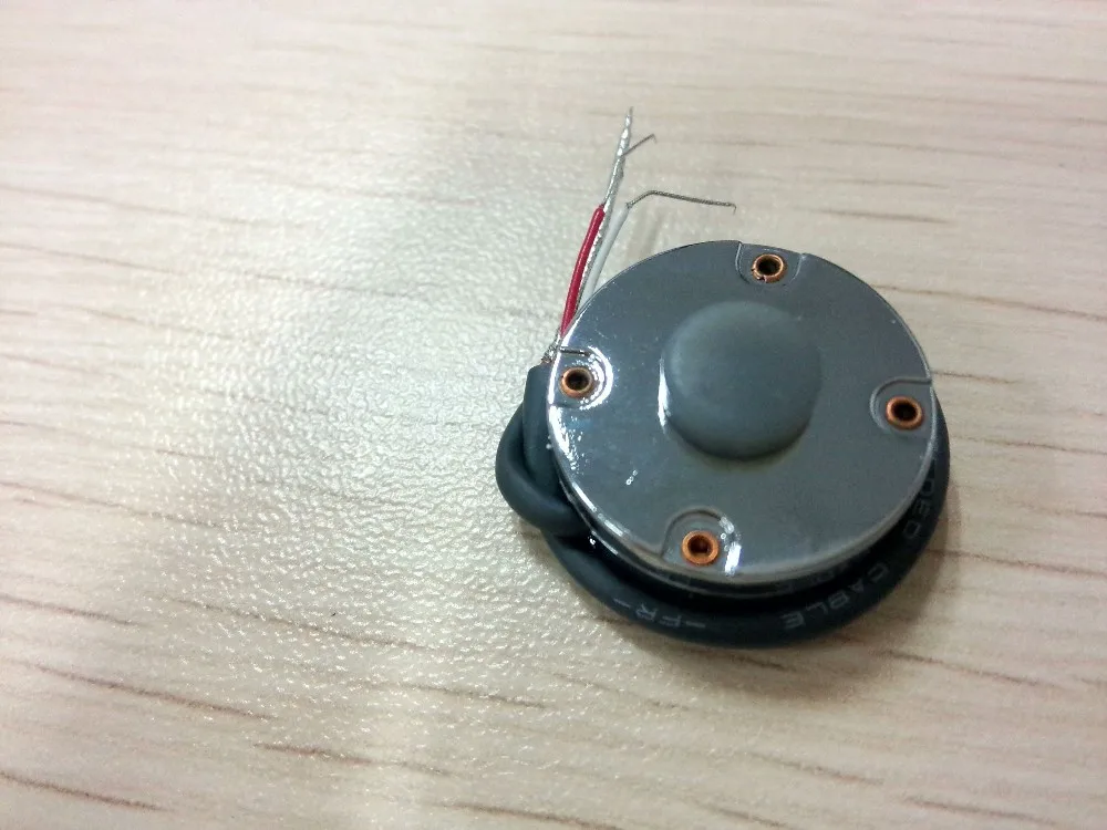
I used the drill for on the four copper rivets to grind them out while holding it in a vice. Eventually they came off freeing the enclosure and the sensor module.![]()
"Not such a tough guy are you now" moment :D
![]()
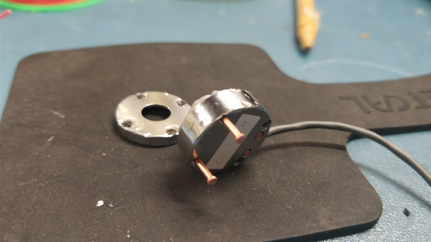
Inside the sensor we also find the transducer and circuitry to pick up the mechanical vibrations and contact sounds from the various sources.
![]()
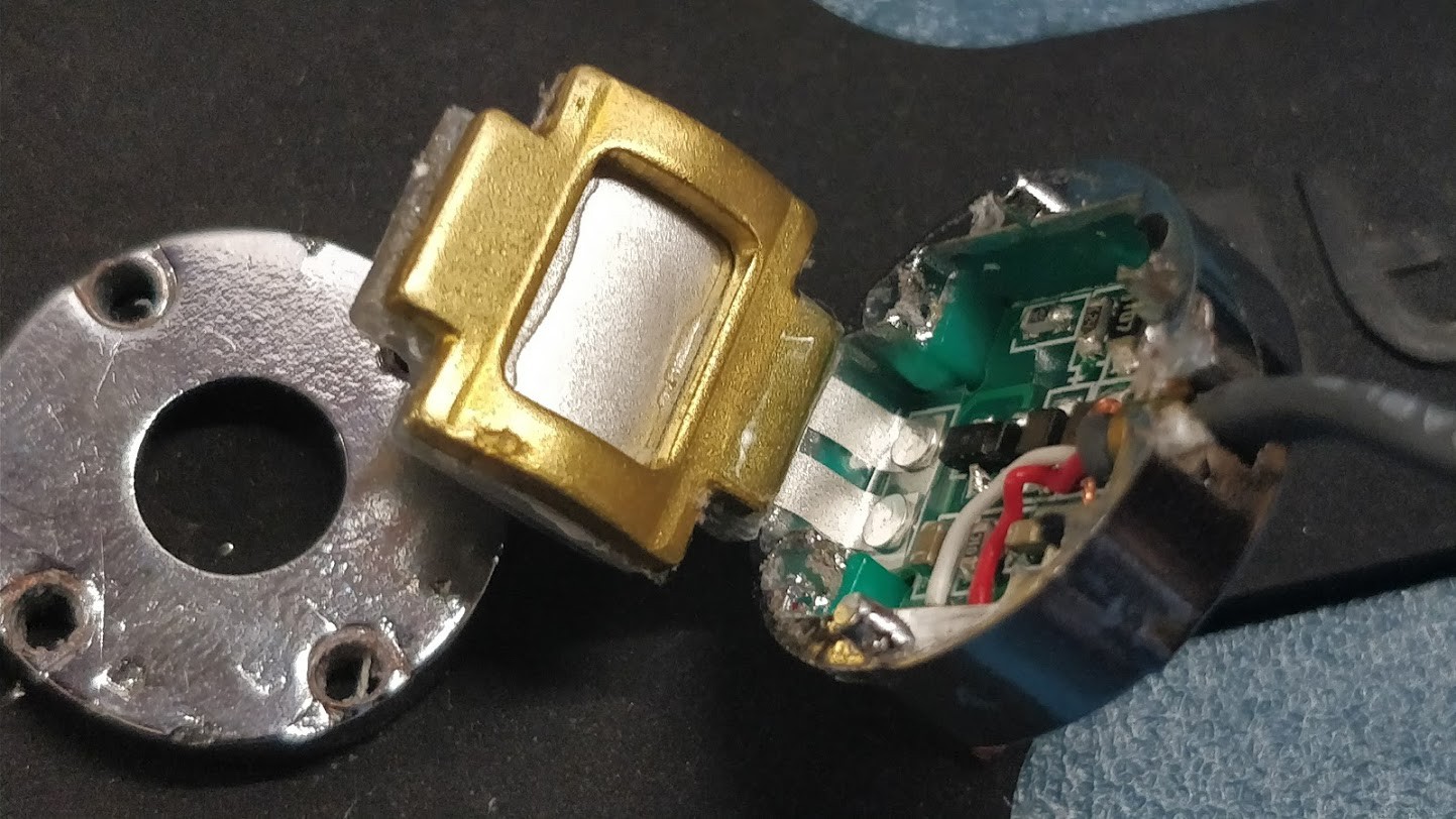
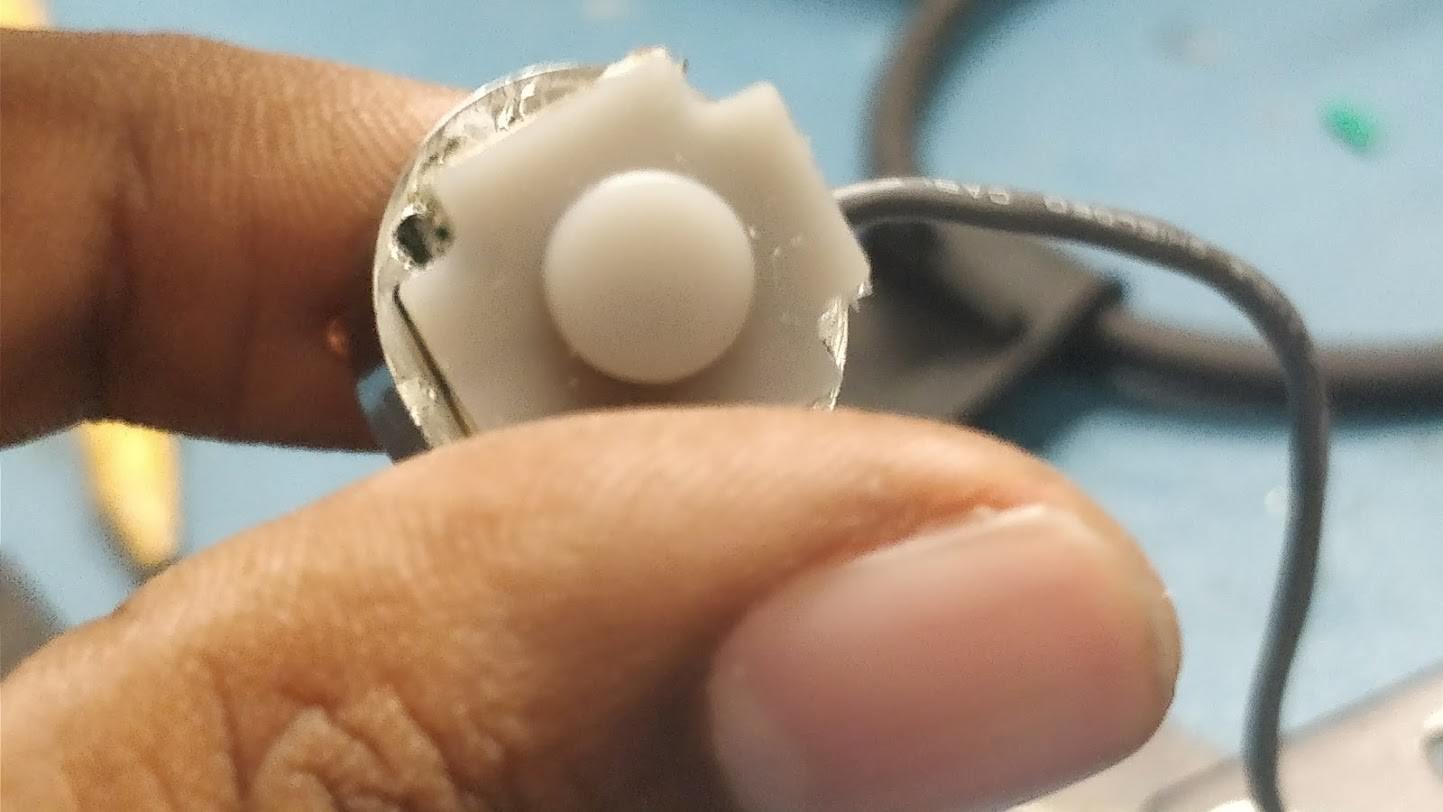
The setup consisted of a rubber extension which was coupled mechanically to a curved PVDF film held in place by a stiff holder. The film was also connected to preamp circuit which outputs amplified signal.
![]()
Top view of the sensor.
From the above we can infer how this device works and why it is quite accurate compared to simply coupling a PVDF film to the knee. Next I would need to design a custom version of this and try to make similar results work.
Also, I think I need to give my hand a bit of rest after all that drilling. -
Joint Sound processing
09/02/2017 at 09:35 • 3 commentsAcoustical emissions have been used as a means to detect failures or damages in materials. It is often used in analyzing structures like bridges, flight wings and other vital structures. The bone itself consists mainly of collagen fibres and an inorganic bone mineral in the form of small crystals. In vivo bone (living bone in the body) contains between 10% and 20% water. Of its dry mass, approximately 60-70% is bone mineral. Doctors frequently use stethescopes to detect many ailments in lungs, heart and including bone damage.
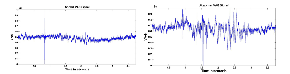
Vibroarthographic (VAG) signals emitted from the knee joint disorder provides an early diagnostic tool. Analysis of the knee sounds can provide a deeper insight into the condition of the joint bone condition along with the cartilage status between the knee. It can allow detection of complications and avoid inflammations at a later stage. During the active movements of the legs such as the flexion and extension, the vibration or auditory signals emits from the mid-patella section of the knee. Healthy cartilage is smooth and slippery producing minimum vibration while deteriorated cartilage is more irregular producing additional vibrations which can be audible in some cases. Vibrations generated by the friction of deteriorated articular surfaces are different in terms of frequency and amplitude compared to healthy ones, originating distinct VAG signals.
(Fig: VAG signals in healthy knee and arthritis knee, Feature extraction of VAG )
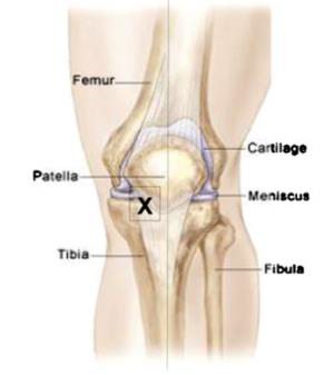
High sensitivity contact microphones and directional electret microphones placed in the medial joint line can pick up the joint clicks and crackling sounds(Fig: Position of the sensor)
Osteoarthritic knees produce more frequent, higher peak, and longer duration acoustic emissions compared to healthy knees The contact microphone currently being evaluated in CM-01B PVDF contact mic and the Knowles BU-23842-000.
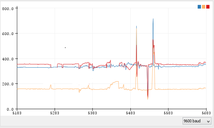
I got the CM-01B contact mic for the starting test. I used the normal analogRead function on the teensy 3.2 at max speed to see what kinda data I was dealing with and I got this.![]()
The orange spikes mark the clicks as I moved my knee up.
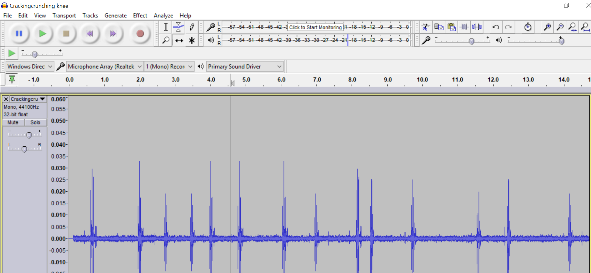
I hooked it up to the Teensy 3.2 due to the amazing audio library Paul has written. I set the filter bandwidth from 50Hz to 3000Hz at start to get some click sounds as I flex my knee. I attached the sensor to my knee with the help of the knee sleeve. I configured the teensy to behave as a USB audio device (Amazing work Paul! Thanks!), Within no time I was able to connect it to audacity and I was able to record and play back the sounds.![]()
#include <Audio.h> #include <Wire.h> #include <SPI.h> #include <SerialFlash.h> // GUItool: begin automatically generated code AudioAnalyzeFFT1024 myFFT; // GUItool: begin automatically generated code AudioInputAnalog adc1; //xy=232.0161895751953,102.03934478759766 AudioFilterStateVariable filter1; //xy=381.01619720458984,139.0393409729004 AudioFilterStateVariable filter2; //xy=510.0161819458008,127.26157188415527 AudioOutputUSB usb1; //xy=657.0162696838379,105.03933811187744 AudioConnection patchCord1(adc1, 0, filter1, 0); AudioConnection patchCord2(filter1, 0, filter2, 0); AudioConnection patchCord3(filter2, 2, usb1, 0); AudioConnection patchCord4(filter2, 2, usb1, 1); AudioConnection patchCord5(filter2, 0, myFFT, 0); // GUItool: end automatically generated code // GUItool: end automatically generated code void setup() { AudioMemory(12); filter1.frequency(2900); filter2.frequency(47); myFFT.windowFunction(AudioWindowHanning1024); } void loop() { float n; int i; if (myFFT.available()) { // each time new FFT data is available // print it all to the Arduino Serial Monitor Serial.print("FFT: "); for (i=0; i<40; i++) { n = myFFT.read(i); if (n >= 0.01) { Serial.print(n); Serial.print(" "); } else { Serial.print(" - "); // don't print "0.00" } } Serial.println(); } } -
IMU data visualization
09/02/2017 at 08:16 • 0 commentsAn inertial measurement unit (IMU) is an electronic device that measures and reports a body's specific force, angular rate, and sometimes the magnetic field surrounding the body, using a combination of accelerometers and gyroscopes, sometimes also magnetometers. They are commonly used in mordern UAV's, Smartphones.
• Accelerometers respond to gravity as well as to their acceleration, and it can be used to estimate the inclination of a body segment, body sway, or for measuring activity levels, however accelerometers have some limitations such as noisy signals.
• Sensitivity improved through the use of a gyroscope through sensor fusion which also provides information on the rotational characteristics.
• In tandem they provide readings which can help determine context of the measurement (Walking vs Lifting foot, Running vs Climbing stairs vs Jumping)
• The BMC150 6DOF IMU is used for the initial prototype but the next revisions would move to the BNO055 9DOF IMU to increase functionality.
The Intel curie comes with the BMC150 IMU inbuilt which can help map the position of the knee. The recent capabilities have enabled the use of an IMU to determine the activity of the user to contextualize measurement.
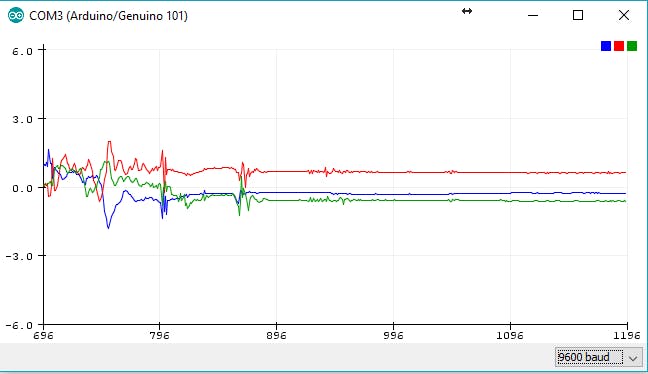
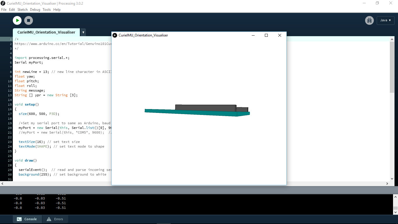
This would help find out if the person is walking, resting, running or climbing stairs. I loaded up a small sketch to test the accelerometer and gyro and I was stunned with the performance of the sensor. The Curie IMU library enables an Arduino or Genuino 101 to read the output of the on-board IMU (Inertial Measurement Unit) containing an accelerometer and a gyroscope and elaborate the raw data coming from it.![]()
![]()
I tried doing some small activities and seeing the response and got this.
-
Joint Angle sensing
09/01/2017 at 02:28 • 0 commentsMeasuring human movements is important before rehabilitation, training or exercises can start. The knee was simply modeled as a hinge joint, and the flexion-extension angle was defined as the angle between the two consecutive joint segments. Existing methods include use of IR emmitter and motion capture cameras, pair of IMU's, electrogoniometers. They are quite expensive and implementation wise the dual IMU method would require wiring which could hinder gait. Our solution was to measure the joint angle using a piezoresisitive fabric sensor.
![Image result for joint angle]() (Fig: Flexion extension angle.)
(Fig: Flexion extension angle.)A textile strain sensor was used on the wearable gesture sensing device to determine the resistance in response to the strain. The textile strain sensor consisted of the elastic piezoresistive fabric, two electrodes, two conductive textile wires. Based on the relationship between the flexion angle and the resistance of the elastic sensor in the flexion-recovery cycles, the relationship between the flexion angle and the resistance of the textile strain sensor during the stretching and recovering movements can thus be obtained.
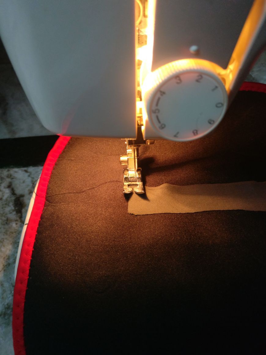
The sensor is based off the Eeonyx SLPA 20kohm fabric cut to a 6cm length. It is then placed in the inside portion of a neoprene knee brace and put to stitch.![]()
(Fig: Positioning the fabric sensor in the knee brace)![]() (Fig: Stitching the sensor to the knee brace)
(Fig: Stitching the sensor to the knee brace)
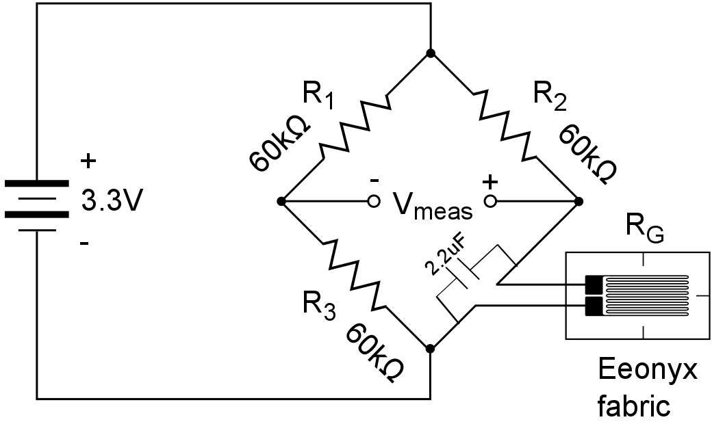
The sensor changes it's resistance as it expands or contracts. A wheatstone bridge network used to measure it accurately and 2.2uF capictor smooths it out.![]()
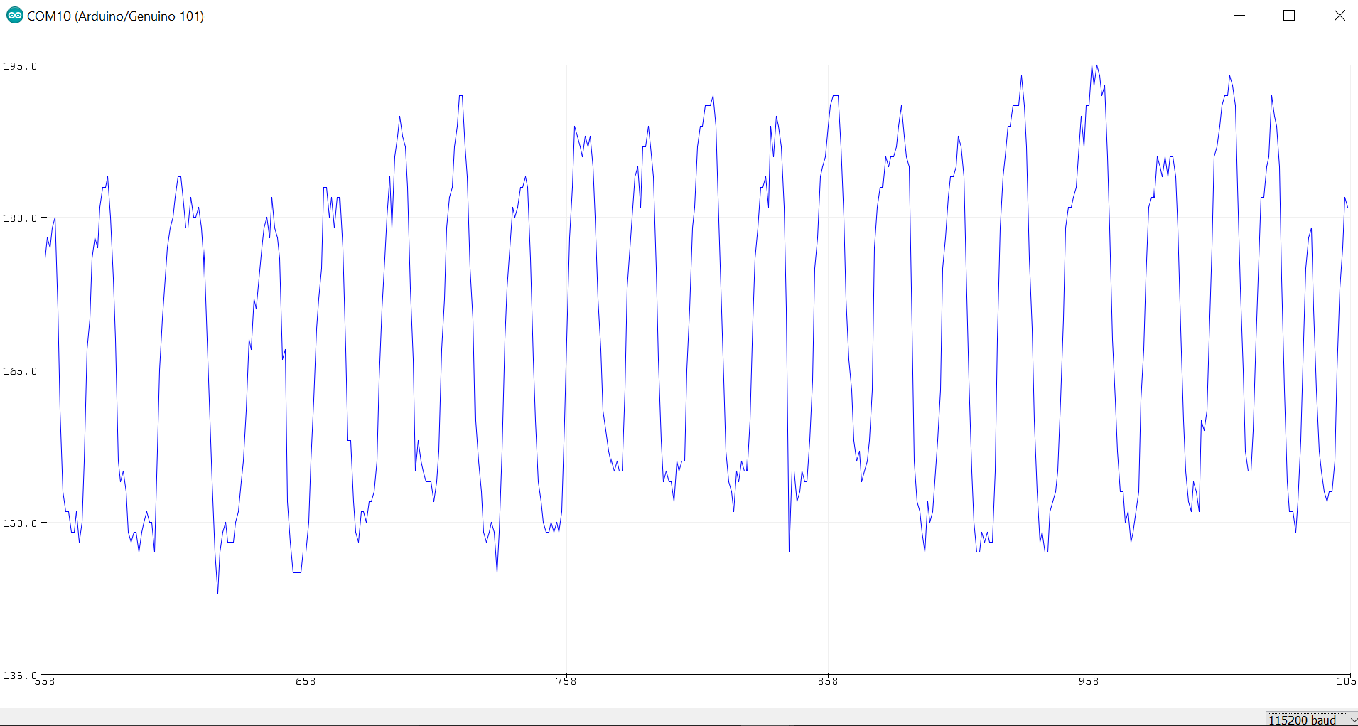
I quickly wrote up an analogRead code on the DFrobot curie to plot the values and lo and behold.
![]()
(Fig: Raw sensor output while doing squats)
Now to do the goniometer functionality, I needed to whip out my protractor to map the angle of the knee joint to to the analog values from the bridge network. This simple method results in the measurement of the joint angle accurately. -
Idea Orgin
08/31/2017 at 05:43 • 0 commentsThis project is a bit close to my heart and I started this out as a way to help my mom who recently had a knee surgery. While the physiotherapy did help at start, She often needed close guidance from the therapist to aid her during rehabilitation. The therapist was rather hard to get hold often due to amount of patients he had to deal with for the same problem.
I wanted to do something which could provide real assistance and insight into her joint condition in a easily understandable manner and also help the physiotherapist increase both his efficiency and standard of care in a home setting. I was suprised to find no solution to this problem in the market which consists of a wide spectrum of fitness monitoring wearables. I hope to fix that with this project and try to illustrate the untapped market of assistive wearable sensors for chronic care. The features I decided to include from start was joint angle monitoring, gait pattern sensing and the acoustic profile sensing of the knee.
I conceptualized a home monitoring system which would allow the patient to track their progress with remote guidance from the physiotherapist. With less than 35% of the outpatients adhering to the training regimen suggested, It is important to have a reinforcement system to evaluate patient compliance and provide them motivation to continue.
Here's a sketch of the initial concept I came up with.![]()
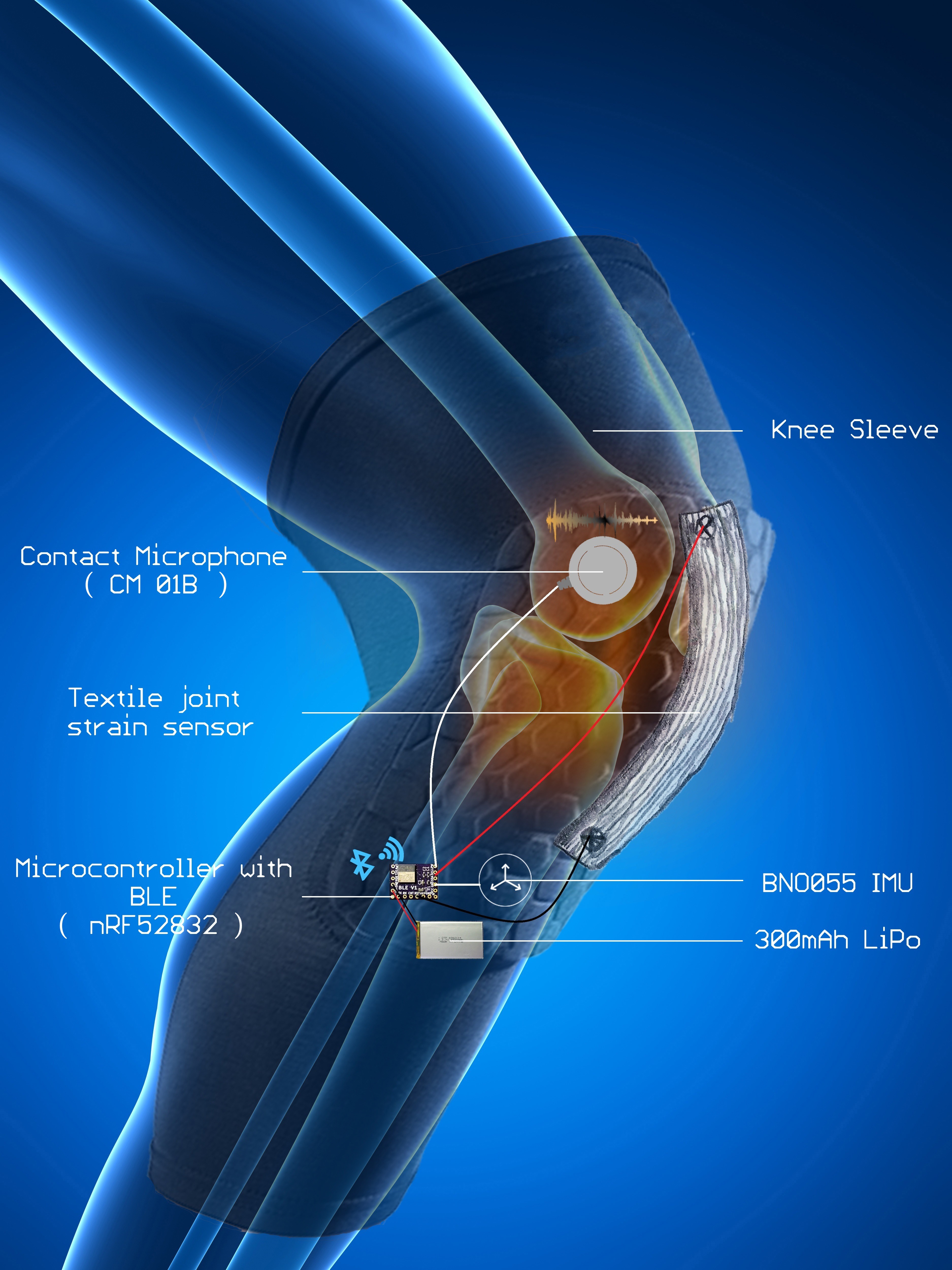
OrthoSense
OrthoSense is a wearable multi-sensory knee sleeve to monitor the progression of Osteoarthritis.
 While this was quite valuable to know I decided to get a more detailed insight by doing a bit of a teardown. Despite seeming to be rather simple an innocous, The device was rather difficult to teardown. I first tried using Allen keys to get the pins out to remove the sensing element from the enclosure but I was unable to get it to work.
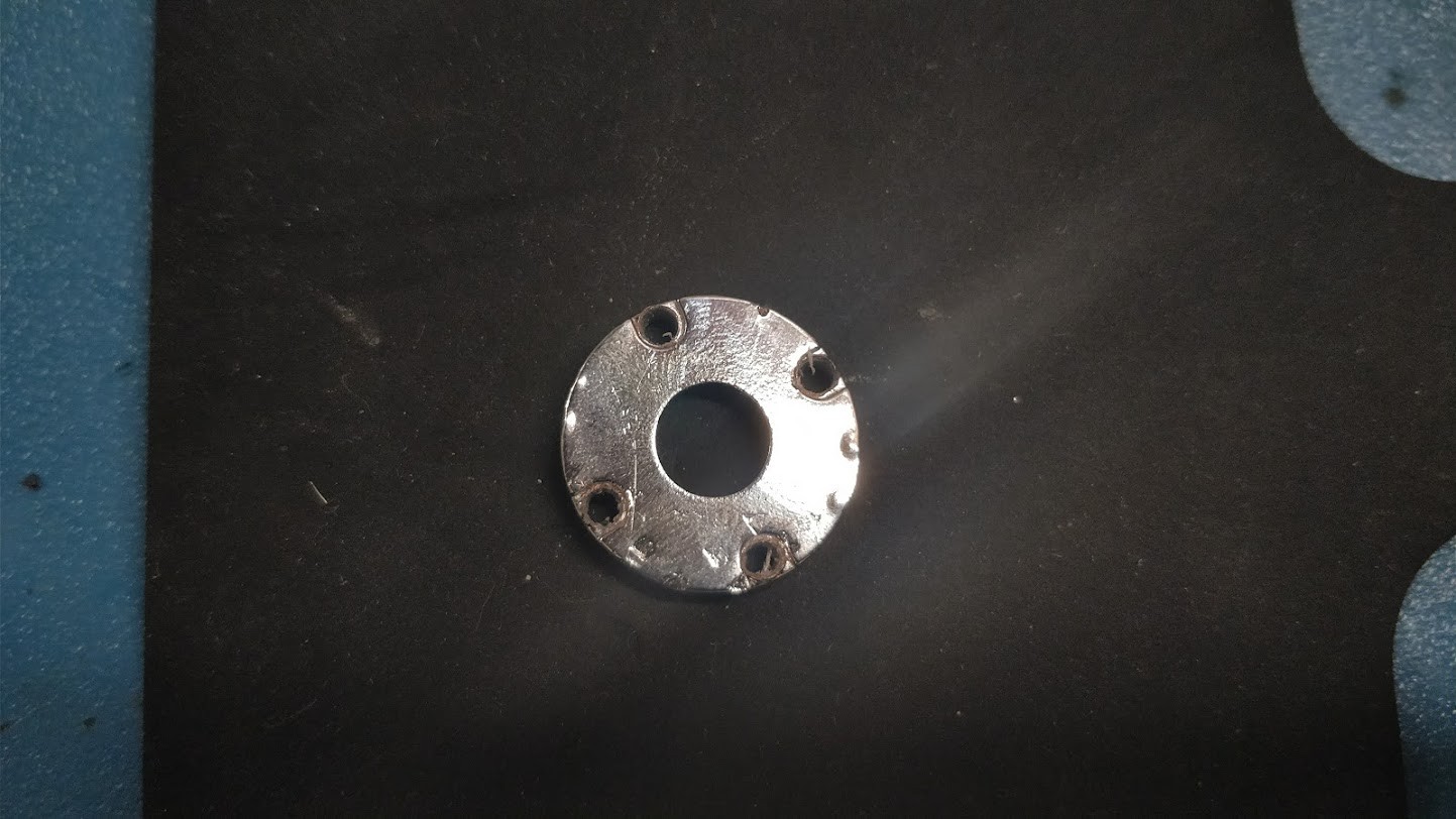
 (Fig: Flexion extension angle.)
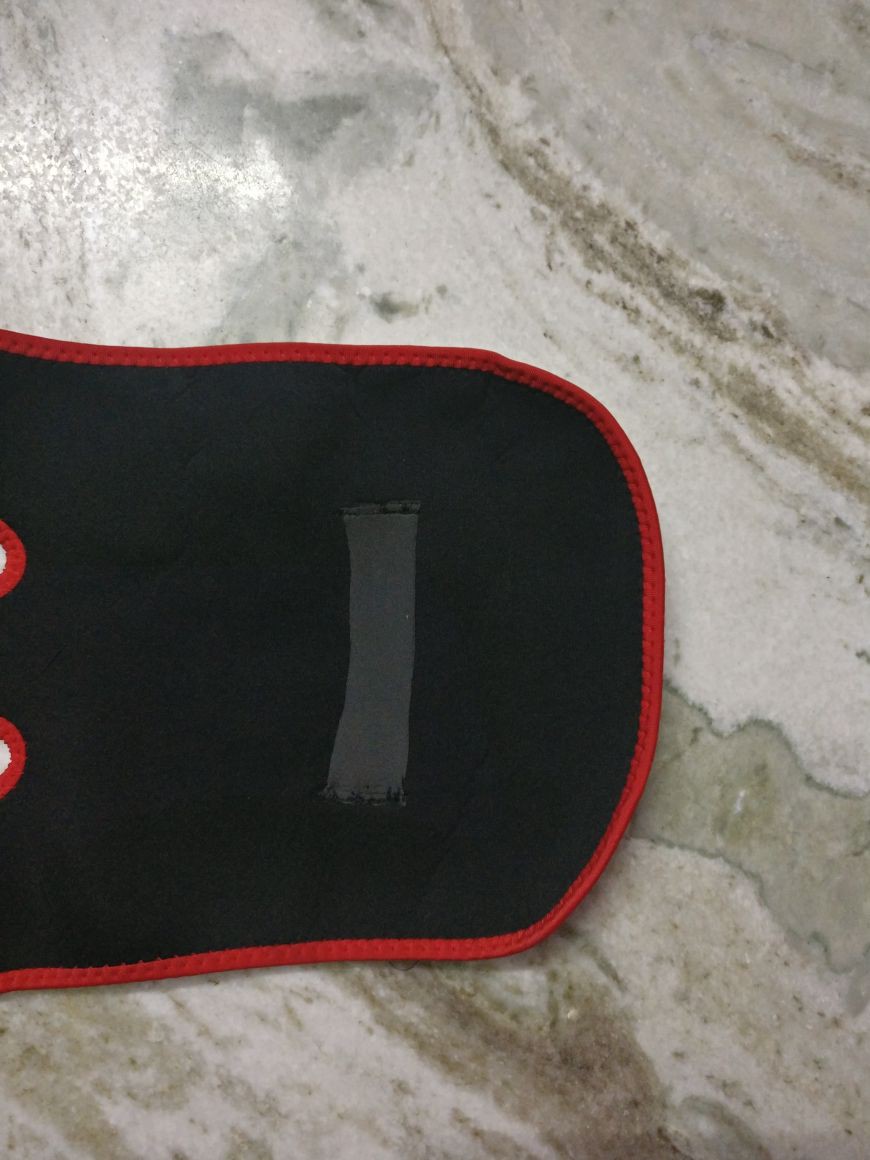
 (Fig: Stitching the sensor to the knee brace)