-
Squirt.
09/22/2018 at 01:15 • 3 commentsThe bearing ID is 8.13mm. The shaft OD is 7.89mm. So I needed something to make up that difference.
I went through all the rolls of tape I had around, and found one where exactly one wrap of tape, not overlapping, would make up the difference. Worked, until now.
The steppers running at the higher current get a little warm now, and I didn't hook up an enable pin on the drivers, so they are always on.
Over the course of the last couple days, I've run them in and out a lot, and eventually an axis got 'rough'. The adhesive had softened and the tape squirted out so the shaft was flopping around. Another axis showed signs of failing soon...
Tried in vain to make some heat shrink work. It goes on, but it never compresses evenly and so the shaft is always wobbly.
Then I tried AL foil. Perfect.
It takes about a 180mm long strip of foil, about 8 smooth and flat wraps, to make up the gap. I end the wrap right where it started, so it's also perfectly centered. I feel much better about 8 wraps versus the one I had before.
There was a learning curve as to how to keep it from un-spiraling when you pull the bearing off though.
Basically, leave some extra and peel from the middle out to the edge... and then compress it. It mushrooms down onto the surface and keeps the whole coil in place.
Pics later. It's a tedious process taking about 5-10 minutes per bearing to do it right, but it's the only way I'm using these shafts without runout.
<EDIT>
The foil has worked well, with the exception of one where it also squirted out the end. One drop of superglue fixed that. I went back and did all the rest.
</EDIT>
-
Weebles wobble
09/21/2018 at 00:06 • 0 commentsNoticed that at the edges of the build area, I was getting some offset from planar on the end effector, not related to the virtual pulleys. The difference in tension between the near and far lines looked to be bending the top corner brackets. On closer inspection, they weren't bending, but instead just wobbling where they slid onto the rods.
To allow them to be removable, I needed them to be a little looser than a press fit, or you end up breaking them when you take it back apart.
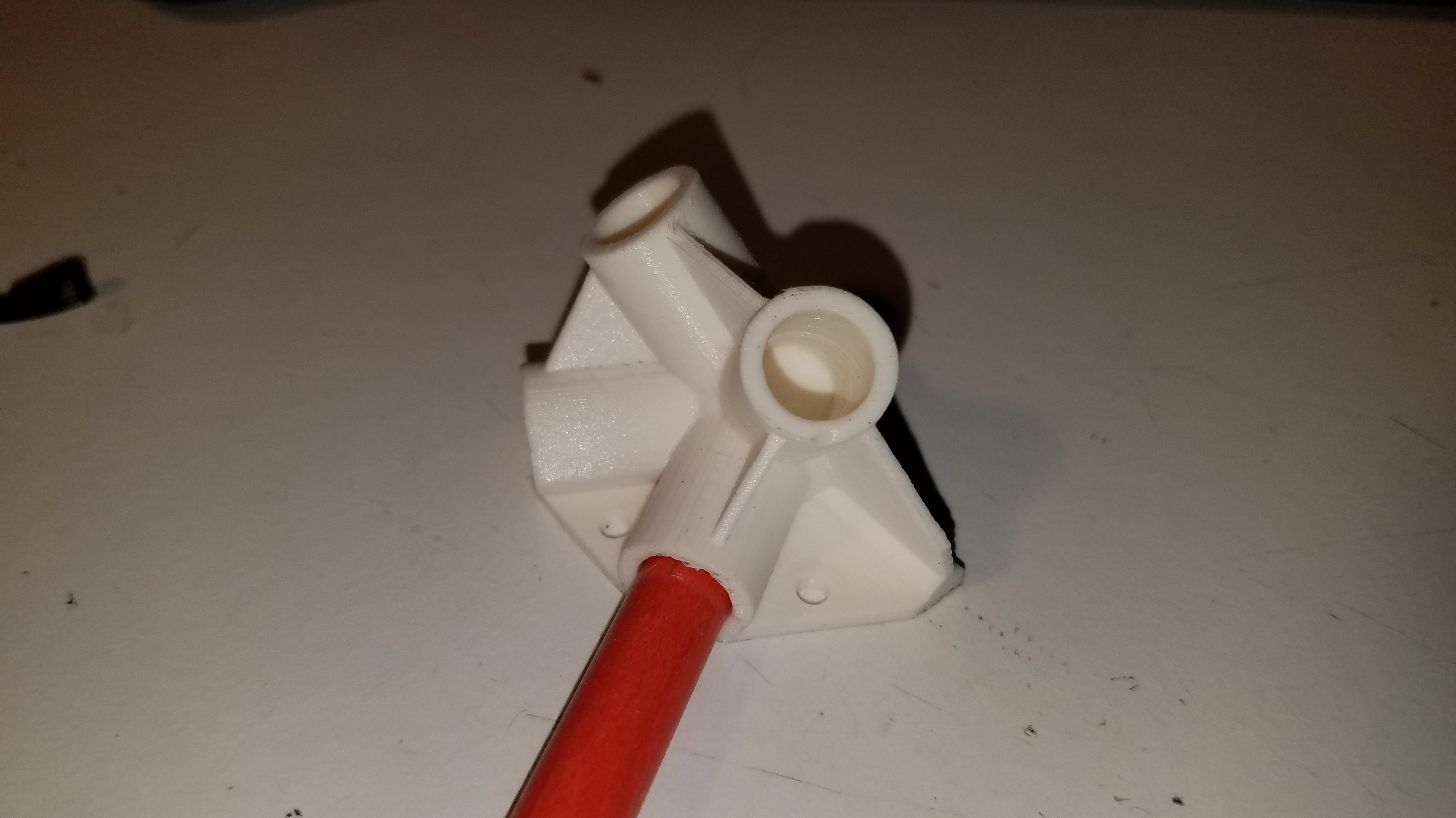
So I've updated the top corners to add some more depth (18mm is now 24mm) to the pockets the support rods go into, and added the bit I've applied to other parts of adding flat spots to the inside of shaft pockets to allow for a tight, but slip fit over a greater range of error in either the rod diameter or the extrusion.
The driveway markers I have vary in diameter over a range of about 0.2mm, which is a huge 2.5% variance given their nominal OD of 7.9mm.
![]()
Reprinted.
Adding the flats seems to have done the trick.
Assembling using the updated parts now.
-
End effector updates
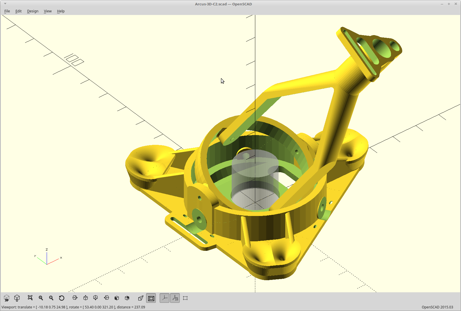
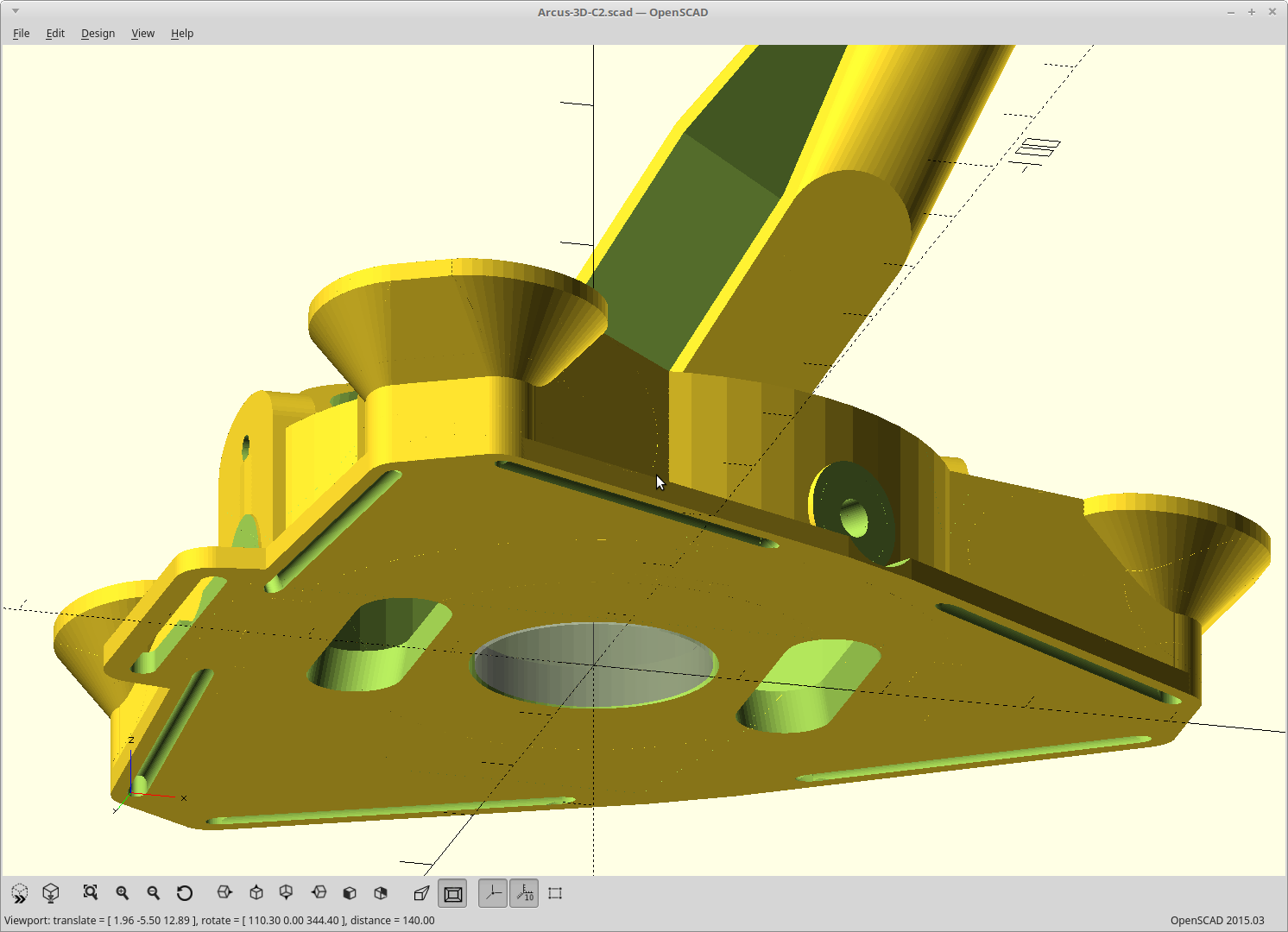
09/14/2018 at 05:41 • 0 commentsModified the end effector, moving the leveling screws to the side and adding cable routes across the bottom so it can sit flat. This should simplify leveling the end effector significantly.
Previously the leveling screws were on the bottom. Getting a screwdriver under there meant the end effector was up in the air, without a reference, while you locked the leveling in place. This will be better.
If all goes as planned, you should be able to loosen the screws, plop it down flat on the bed, and tighten them again and be perfectly level.
![]()
For this version I also added a switch which enables/disables the fan mount and drops the ribbon cable guide for the Pi camera used on the P1 in its place. I also added another optional guide to the pushrod joint to match and reshaped the existing guide to pass the 3 pin servo plugs through.
<EDIT> Since this, I have also moved the virtual pulleys up to be on the same level as my pushrod gimbal. Here you can see the new cable slots also.
![]()
It's on the P1 now, and working like a charm.
</EDIT>
-
Kinematics
09/10/2018 at 17:39 • 0 commentsI took the time to make my recent changes a proper pull request against Machinekit so people can eliminate this bit from the task of getting this up and running.
It fixes the problem of tripodkins not working properly at first if you are inverted (hanging) like this project.
-
Renewed Purpose.
08/06/2018 at 07:40 • 0 commentsI've decided to use this as my platform for driving the P1 and figured out how I can do it.
Made some minor updates to the model to reduce the filament required and also to strengthen some areas that needed it.
Updated parts are printing.. Fast.
Well, as fast as I can go with a single filament driving it anyway and still have good results... about 120mm/sec.
Edit: One down, 5 more to go..
![]()
-
End Effector print
03/14/2018 at 09:23 • 0 commentsEn-biggend the end effector wire slots in prep for passing a ribbon cable from the P1 and reprinted it.
32x timelapse of the print.
-
Spin and fold.
03/06/2018 at 04:31 • 6 commentsDid a couple virtual experiments with how I could hinge the corners to enable 'spin folding'. Rotate the top 60 degrees and it lowers to sit on the matching bottom.
Right now, you have to actually remove the 6 vertical members to fold it down. This would allow you to just unhook and fold up 3 of the arms, and then turn/lower the top to meet the bottom with the remaining 3 arms still attached at both ends.
Using ball joints this would be super easy, but that would also sacrifice a ton of rigidity. Making the joints as pivots will work much better, but then the pivot axis vector and arm length/position has to be carefully planned.
Here is the best I got so far.
![]()
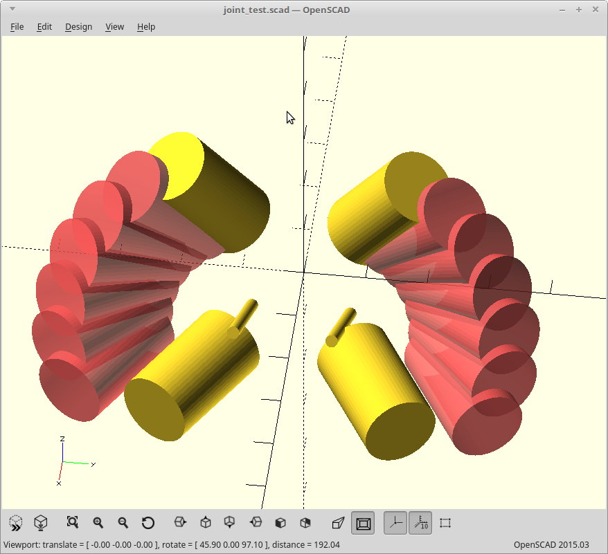
The large yellow cylinders are the current angles needed by the joints, and the pink ones are what you get when you rotate them about the axis represented by the smaller yellow cylinders. The rotational axis vector was determined first and properly (as best as I can tell with just the math) represents the swing required of the arms during the 'spin fold'.
Then I just iterated on offsets of the rotational axis until I got a path where the arm length matches reality.
I believe if I put a hard stop in the rotation in the extended position which is attached to the part of the triangle that stays static, I won't be giving up as much rigidity to do this either.
The current iteration is still not good enough though, as that folded arm position intersects with where I currently have stepper mounts.
It's a side goal, and the rest of the project can move on without it, but this would definitely be cooler.
EDIT: If anyone is ambitious enough to check my math, here is the 'so far' joint model in OpenSCAD.
Only works for one of the two joints though, as the second joint (from the opposing arm) would actually occupy the same space as the first when folded... but that's just details. :) I could use a different set of offsets for that joint, and the ends don't acutally have to line up as they will be disconnected for that one.
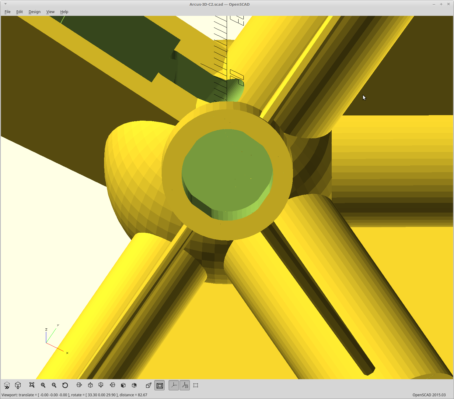
module joint_test() { wall_thickness=2; support_rod_dia=8.25; // Driveway marker diameter. support_rod_depth=20; // Depth of the pockets for support rods. roswell_constant=19.47; q=32; x=q/2; y=q/4; z=q/8; translate([x,y,z]) rotate([0,45+roswell_constant/2,0]) { cylinder(r=1,h=30,center=true); for (i=[15,30,45,60,75,90]) rotate([0,-45-roswell_constant/2,-i]) translate([-x,-y,-z]) rotate([-30,roswell_constant,0]) translate([0,0,support_rod_depth*1.5]) #cylinder(r=support_rod_dia/2+wall_thickness,h=support_rod_depth,center=true); } translate([x,-y,z]) rotate([0,45+roswell_constant/2,0]) { cylinder(r=1,h=30,center=true); for (i=[15,30,45,60,75,90]) rotate([0,-45-roswell_constant/2,i]) translate([-x,y,-z]) rotate([30,roswell_constant,0]) translate([0,0,support_rod_depth*1.5]) #cylinder(r=support_rod_dia/2+wall_thickness,h=support_rod_depth,center=true); } rotate([-30,roswell_constant,0]) translate([0,0,support_rod_depth*1.5]) cylinder(r=support_rod_dia/2+wall_thickness,h=support_rod_depth,center=true); rotate([-30,90,0]) translate([0,0,support_rod_depth*1.5]) cylinder(r=support_rod_dia/2+wall_thickness,h=support_rod_depth,center=true); rotate([30,roswell_constant,0]) translate([0,0,support_rod_depth*1.5]) cylinder(r=support_rod_dia/2+wall_thickness,h=support_rod_depth,center=true); rotate([30,90,0]) translate([0,0,support_rod_depth*1.5]) cylinder(r=support_rod_dia/2+wall_thickness,h=support_rod_depth,center=true); } joint_test(); -
You will be Assembled.
03/05/2018 at 02:37 • 1 commentRyden and I were finally both able to complete our requisite tasks with enough time to spare to make the assembly video(s)!
Part 1
10 minutes really flies by and we ran out of recording time, so there is a..
Part 2
Thank you Ryden for your assistance.
-
Happy week after.
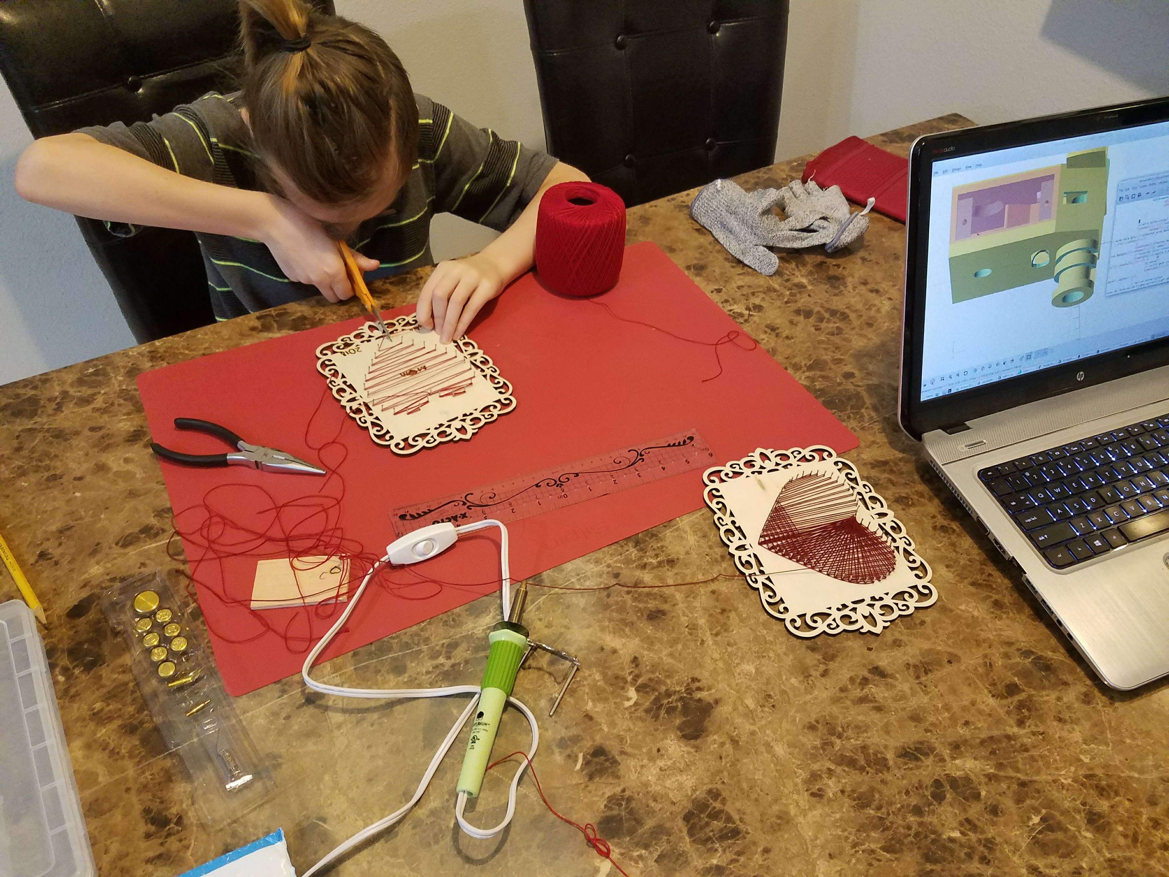
02/18/2018 at 00:08 • 2 commentsLast weekend was consumed by my son wanting to make projects for mommy for Valentine's day, and you can't really say no to that. There was even wood burning involved.
![]()
So we'll try to work on the final assembly again tomorrow.
-
The waiting... is the hardest part
02/10/2018 at 06:19 • 0 commentsI promised I would do the assembly video with my son. So I am...
I will make that happen this weekend.
The good news while I've been waiting for him, I've made progress on the PnP head so I can use the ficidual camera for calibrating the printer now. That should allow me to detect anomalies I wouldn't have been able to before (like how far off my guesstimated virtual pulley shape really is).
In the meantime here is a most epic David Bowie reference.
Arcus-3D-C1 - Cable 3D printer
3D printable, Open Source Hardware, tripod kinematics, cable driven 3D printer
 MasterOfNull