-
Enter The Matrix
10/22/2017 at 12:37 • 0 comments
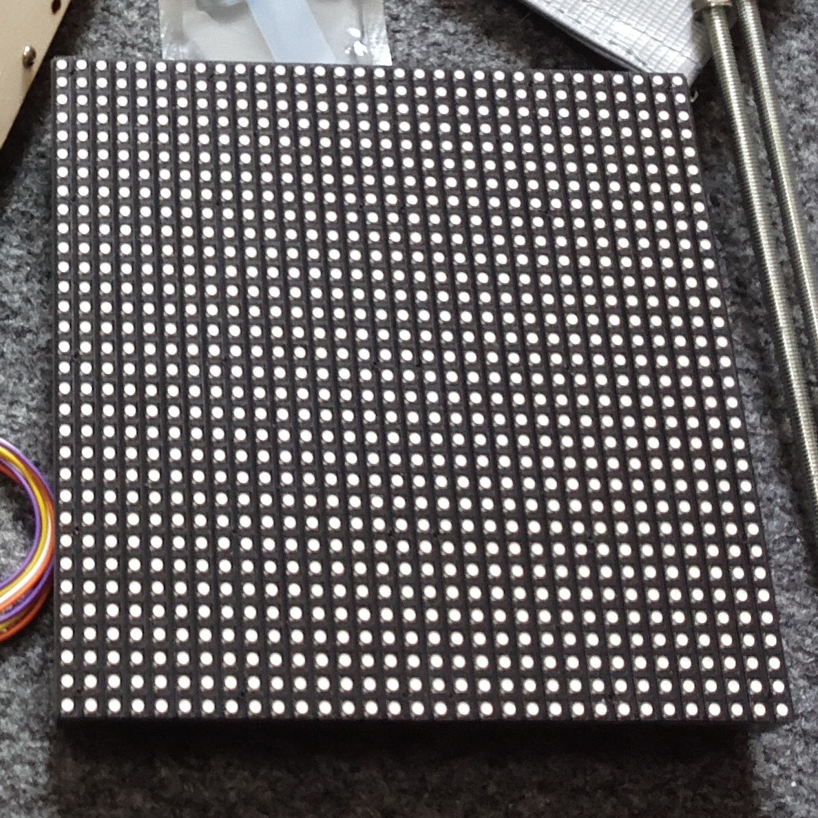
OK, so the reason this robot is called Bot Matrix, is because one of the central components is a 32x32 RGB LED matrix.![]()
These LED panels are the type used in Jumbotron screens or advertising billboards. They have a set of shift-registers and constant current drivers on-board, and use a somewhat standard interface which seems to be called HUB75.
Sourcing the Panel
HUB75 panels aren't too hard to find - though I did have a certain amount of trouble getting a 5mm-pitch, 32x32 pixel panel.
Pimoroni sell P4 and P6 (4mm/6mm pitch): https://shop.pimoroni.com/products/rgb-led-matrix-panel
Adafruit have a selection, but their 32x32 P5 is $45 USD! (Plus shipping from the US), which was too much for me: https://www.adafruit.com/category/327
I went shopping on Aliexpress, and found plenty for around $20-$30 USD, delivered to the UK: https://www.aliexpress.com/wholesale?catId=0&initiative_id=SB_20171022045534&isPremium=y&SearchText=P5+rgb+matrix
Driving the Panel
The panels themselves are not able to display an image - they must be continually scanned with data, and if PWM is desired/required, then that needs to be provided in the input too. This means they have pretty hefty driver requirements - and in commercial setups they seem to often use FPGAs to generate the control signals.
Hackaday previously featured this project by Frans-Willem which drives a set of HUB75 panels from an STM32F407 - and I just so happened to have bought an STM32F407 for something else, so I set to trying to use that code to drive my panel.
I'll forgo a detailed description of how the drive signals work - Frans-Willem already did a great job explaining it in his writeup.
Basically, there's a set of pins which choose which row of the panel to activate, a set of pins connected to the shift registers to shift data in to that row, and a set of pins to latch and display that line.
You have to scan through each line, latching in and displaying data for that line before moving on to the next.
If you want full colour (not just 3-bit colour) you also need PWM. Frans-Willem came up with an elegant solution whereby the appropriate bit-patterns to give PWM-ed colours is stored in memory, then directly written to the STM32's output pins using DMA - this puts full-color, 60 FPS refresh rate on a 32x32 panel within reach of an STM32F4!
The quirks of my specific panel
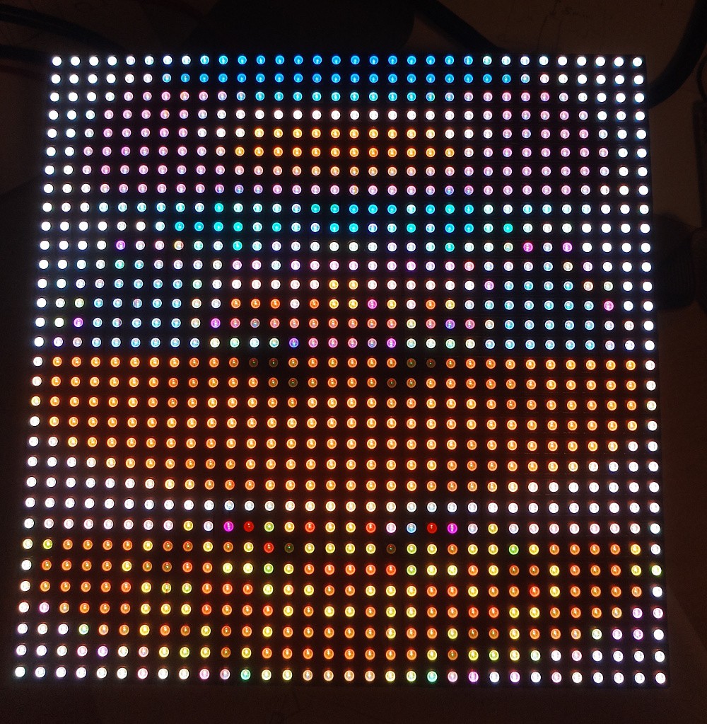
The seller I bought my panel from claimed it was 1/16th scan - this means that the rows are scanned in groups of 16 rows, with two busses. This eventually turned out not to be the case - it took me a long time to figure out what was wrong, as there was another issue causing strange output.
![]()
Eventually, I figured out it was in-fact 1/8th scan, as evidenced by the "D" pin being tied permanently to ground, and hidden under a sticker on the board, it indeed said "P5-32x32-8S-75-13A". So once I had changed the config to expect a 1/8th scan instead of 1/16th, I started getting output that made some sense.
There was still a problem - I was now displaying "stripes" of 8 rows of pixels, but the stripes were in the wrong order. It turns out the way the shift registers relate to the panel pixels are non-intuitive on my panel:
commit 6c1b8b84e7d8927119d1bfaf2ba36b600a05bbaa
Author: XXX
Date:   Sat Sep 9 15:57:10 2017 +0100
    Add remapping

    My panel has a strange pixel layout. Though the physical dimensions are
    32x32, logically the electronics are laid out as 1/8 scan with 64 pixels
    per row.

    If the 32x32 panel was split up as below:

     0                              31
     +---------------+---------------+ 0
     |               A               |
     |                               |
     +---------------+---------------+ 8
     |               B               |
     |                               |
     +---------------+---------------+ 16
     |               C               |
     |                               |
     +---------------+---------------+ 24
     |               D               |
     |                               |
     +---------------+---------------+

    Then the physical shift registers are arranged as 64x16, with the layout
    below:

     0                                                              63
     +---------------+---------------+---------------+---------------+ 0
     |               B               |               A               |    BUS0
     |                               |                               |
     +---------------+---------------+---------------+---------------+ 8
     |               D               |               C               |    BUS1
     |                               |                               |
     +---------------+---------------+---------------+---------------+

    To support this, add a function which is called by "framebuffer_write()"
    which adjusts the given offset to map it to the different display
    layout.
I've seen talk around the web of other panel layouts - so if you do embark on trying to drive one of these things, be aware you might need to reverse-engineer the pixel layout.
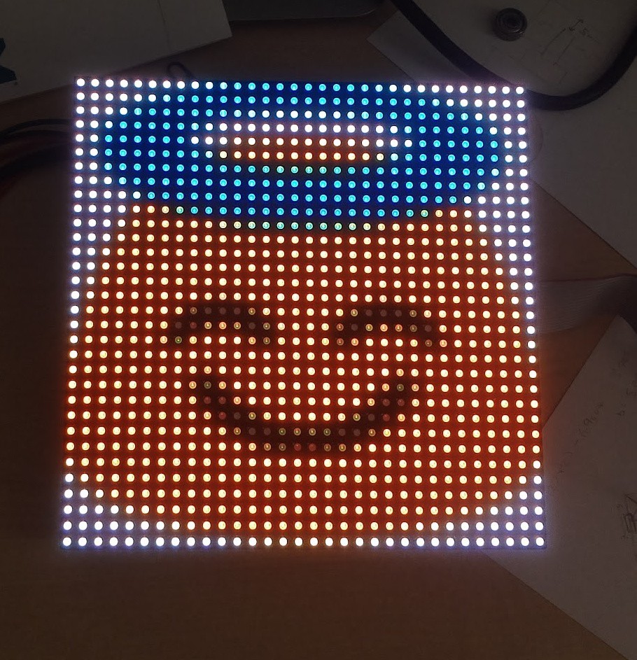
Once I'd finally figured out how the pixels are laid out, I added a routine to Frans-Willem's code to map from the "standard" pixel layout to my panel's quirky one. I wanted to do this on the microcontroller instead of the "host" (Pi or whatever), so that the host can just send raster-scan-order data.
With all that done, I could finally display an actual image! (Exported from GIMP as a C-header):
![]()
Control over SPI
I was keen to use SPI to upload my pixel data to the panel, as the Pi3 only has one "good" serial port, and that's connected to the Bluetooth chip (which I also want).
I set about adding a SPI slave implementation to receive pixel data from the SPI and write it to the framebuffer.
It took me quite a while to get the DMA state machine working reliably, but I eventually got there, and could send data from the Pi over SPI. The SPI stays stable up to around 3 MHz, and a framebuffer is about 4kB, so theoretically, the max framerate dictated by the SPI would be:
Totally adequate (but remember it's an upper limit, if the SPI runs at full speed all the time - not the case because both the Pi and the microcontroller need to do some processing).
I grabbed some Matrix code off the net and made it work on my panel - python manages to get 45 FPS in real-world performance:
I did some investigation in to where the bottle-neck was, and found that the microcontroller was spending a huge amount of time writing the framebuffer - as I mentioned at the start, the way the code works is by generating a special bit-pattern in memory representing the PWM signals. Converting the pixel data into this representation was taking a lot of CPU time.
My layout re-mapping was responsible for about 10% of that, but even without that I would only be able to get 45 FPS reliably.
A quick google for "STM32F4 overclock" revealed this, which after dropping in to my project, overclocked my micro from 168 MHz to 240 MHz, and meant frame-processing time was down to around 15 ms - perfect for a solid 60 FPS frame-rate. The chip gets ever-so-slightly warm, but it was getting warm running at 100% all the time at 168 MHz anyway, and I'm not too concerned about longevity.
Wrapping up mechanics and electronics
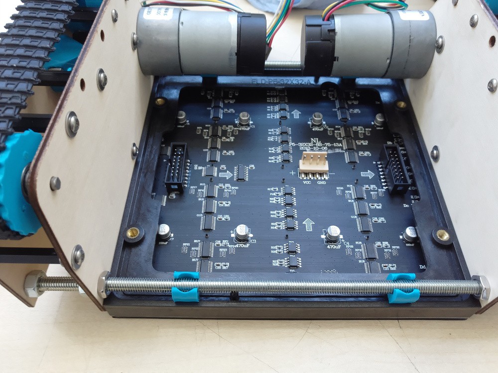
OK, so with the microcontroller software in-place, I set about getting the module ready to go on-to the robot.
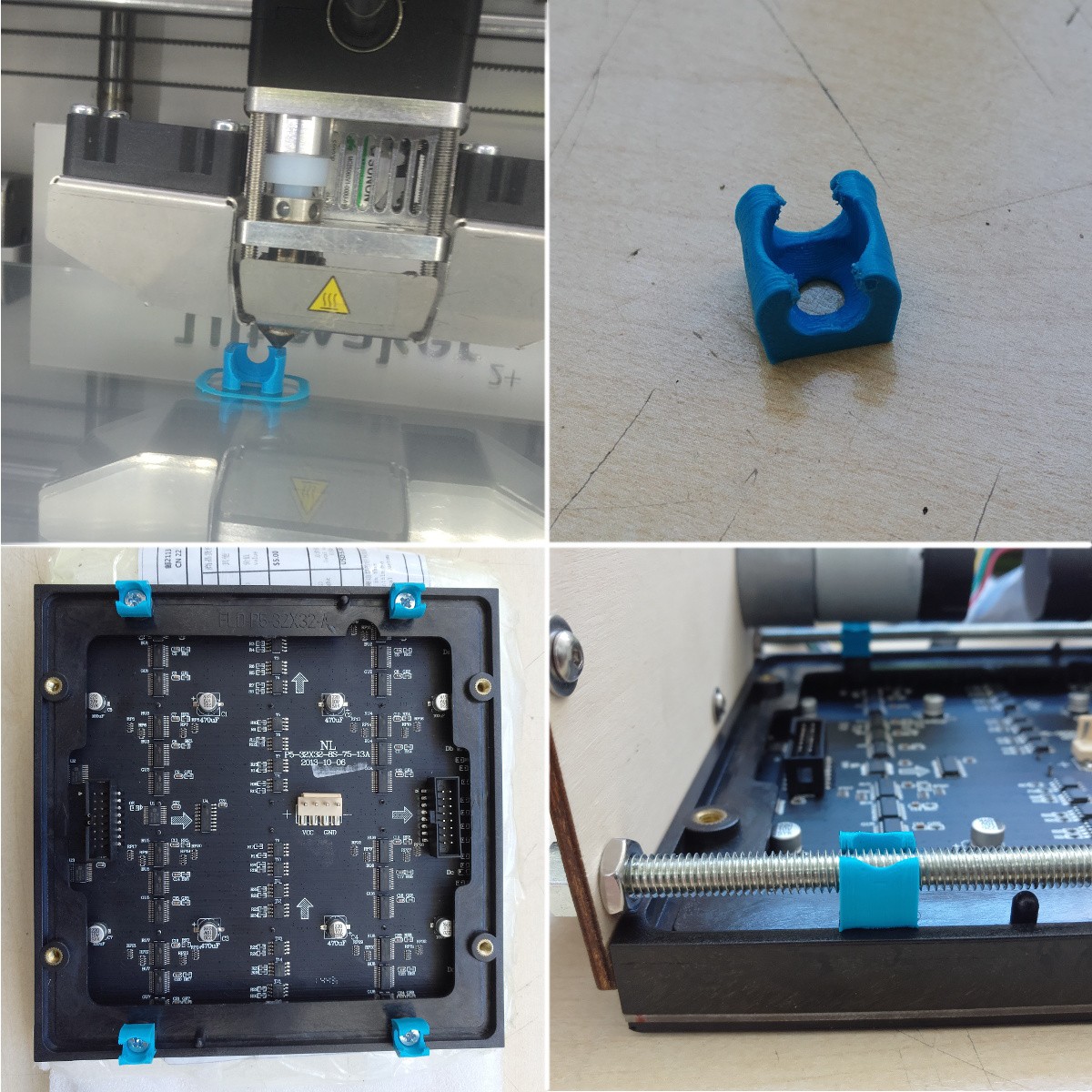
First I needed a way to attach it to the structure of the 'bot. I settled on 3D-printing some simple clips, which clip on to the threaded rods holding the motors together. These turned out way better than I had ever expected, and they hold the panel super-securely
![]()
![]()
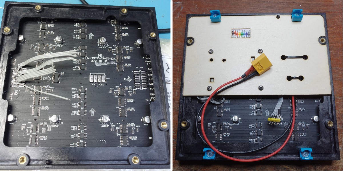
I am really tight on space in the robot, so I wanted to get a power supply and the microcontroller integrated in to the actual panel itself to get the whole assembly self-contained (for modularity) and as small as possible.
I de-soldered all the connectors, and spent a painstaking afternoon hard-wiring the microcontroller and power-supply board on to the panel. I then attached the electronics to a laser-cut panel pressed in to the underside of the matrix.
The end result is a self-contained panel module, with external connections for power ("any" voltage - there's a buck converter module integrated - I can connect the battery directly), and SPI.
![]()
One final little detail, is that when the panel powers on, before the micro takes over, or if the micro is in the bootloader, then the panel ends up displaying "random" data, which is ugly, hurts your eyes, and pulls a lot of current (no scanning == solid LEDs). So, I've connected a weak (22k) pull-up between the OE pin and Vcc, and made that pin on the micro open-drain.
-
Baby's first steps! (More tracks)
09/26/2017 at 21:02 • 0 commentsSo, having been away at XDC (https://www.x.org/wiki/Events/XDC2017/) last week, and having finalised the CAD designs for my tracks just before I left, I was itching to get back and build a new pair of track modules.
I managed to get on to the Makespace laser and 3D printer last night and get all the parts I needed to build the track modules:
![]()
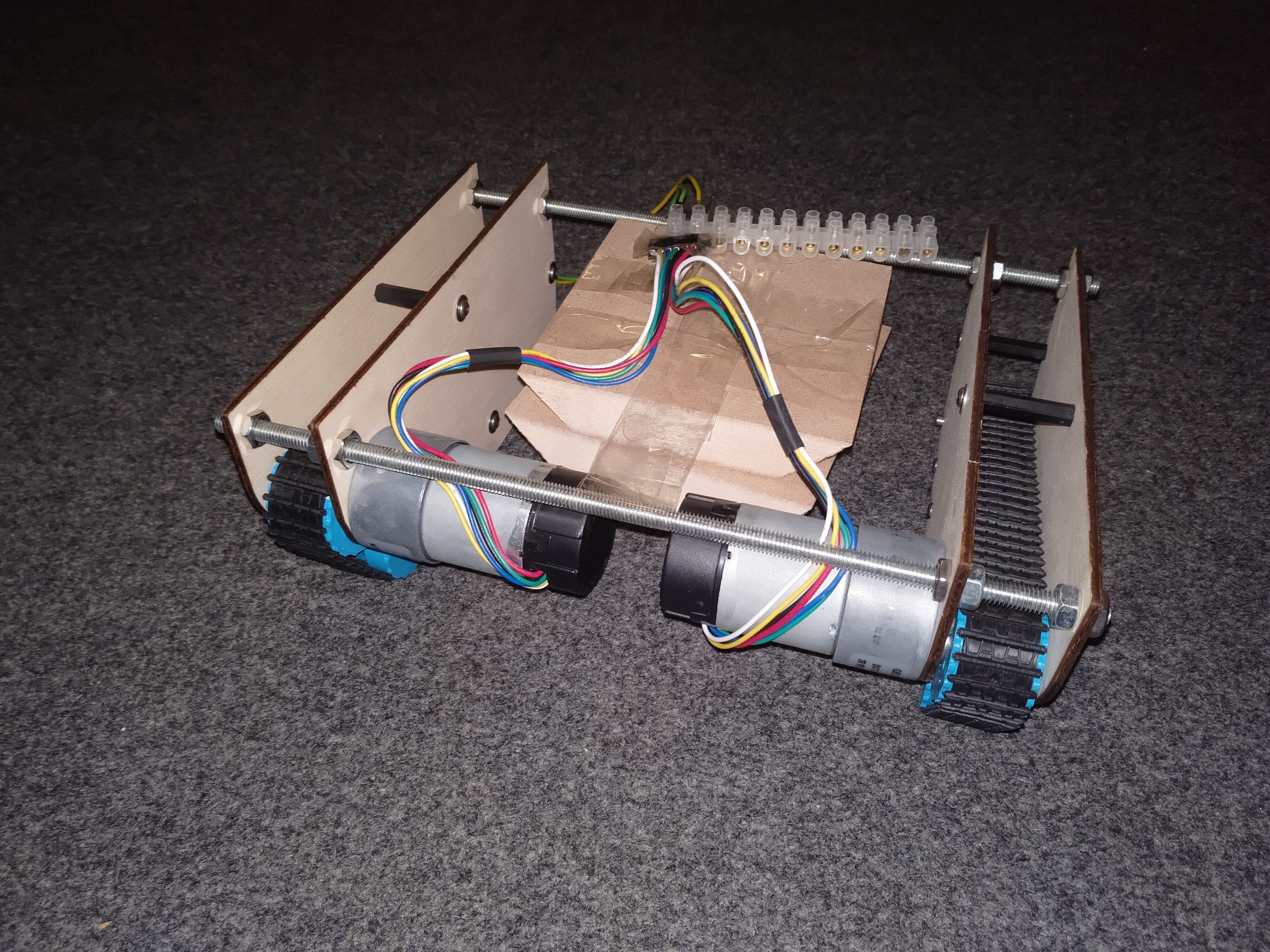
So now it's starting to look a bit more like a thing that can drive. And it can drive, but it turns out I have quite a problem with the centre of gravity being too high and/or too far forward (better with sound for comedic effect):
The MDF blocks sellotaped in the middle are just to add some weight - because otherwise the motors make it really really front heavy, and it falls over all the time. I haven't got any controller electronics on it yet, both motors are just plugged directly in to a DC supply.
There's plenty of other kit to add in to the robot, which should quite significantly change the weight distribution and dynamics, so I'm not too concerned about the instability just yet - but I will bear in mind that I need to design the rest of it to get as much weight low down as possible! And
-
Tracks!
09/03/2017 at 17:43 • 0 commentsOK, another weekend, another subsystem. This time I've been working on a prototype for my tracks module.
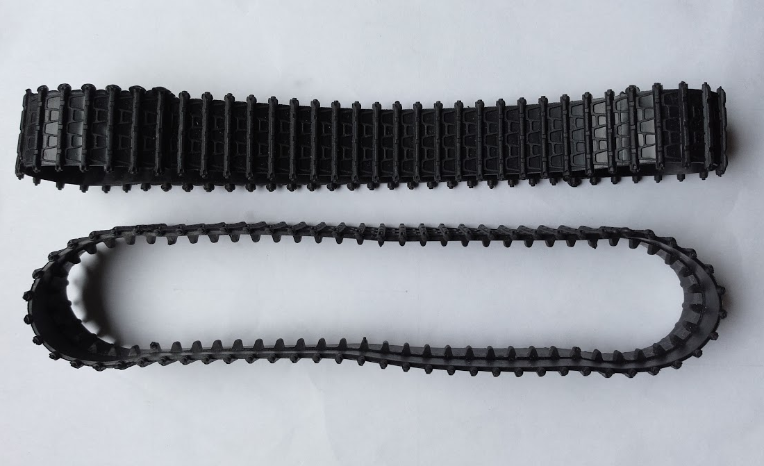
The robot will be tracked (tank, caterpillar whatever) - I bought some rubber tank tracks from Aliexpress (type D), and assumed I would sort out my own pulleys either lasering, 3D printing or milling them.
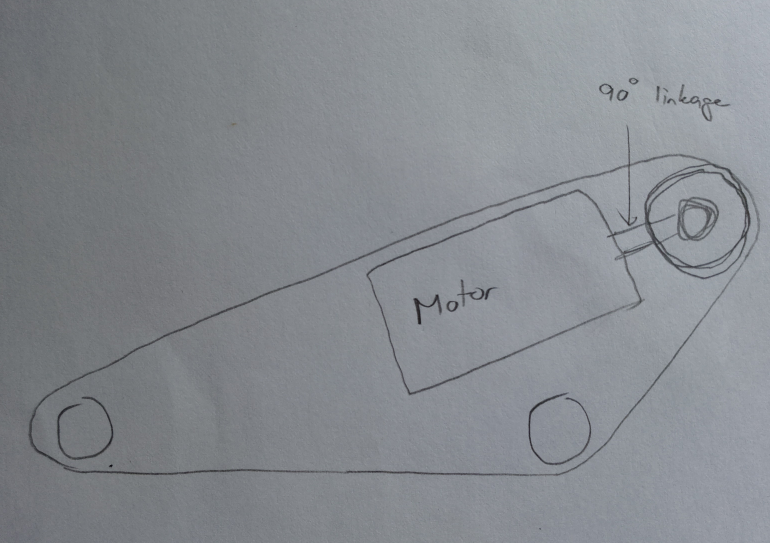
I originally wanted to put the motor inside the circumference of the track - aligned parallel with the direction of travel - and then have a 90° linkage to transfer the motion to the pulleys. This would save space inside the fairly cramped robot, and also give a nicely centralised, very low centre of gravity:
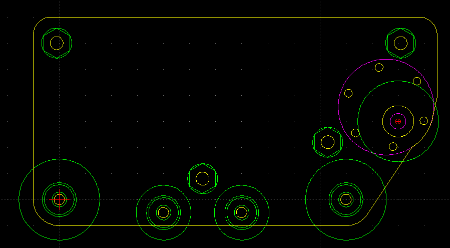
Unfortunately, the tracks are too short to give me space for the motors, and so instead I've had to opt for pretty much the opposite - the motors will be directly connected to the drive pulley, at perpendicular to the direction of travel - and will be pretty high up! (Magenta is the motor in this image):
Pulleys
The first challenge was to reverse-engineer a pulley by measuring the track. The tracks didn't come with any kind of engineering drawing or measurements, so I had to wing it by hand. One significant challenge is that the rubber obviously moves when you try to measure it... any pressure from a caliper squashes the rubber and your reading is no good.
The tracks have a row of teeth along the centre, which ideally I want to drive. They also have castellations along the outside edges which we could also use for drive.
My big fear is throwing a track, so I really want as much registration as possible to avoid the track falling off. The secondary concern is to avoid slippage on the wheels so that my motor encoders can be at least some use for dead-reckoning tracking.
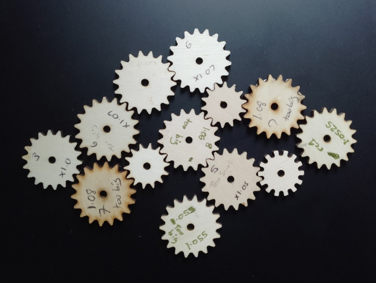
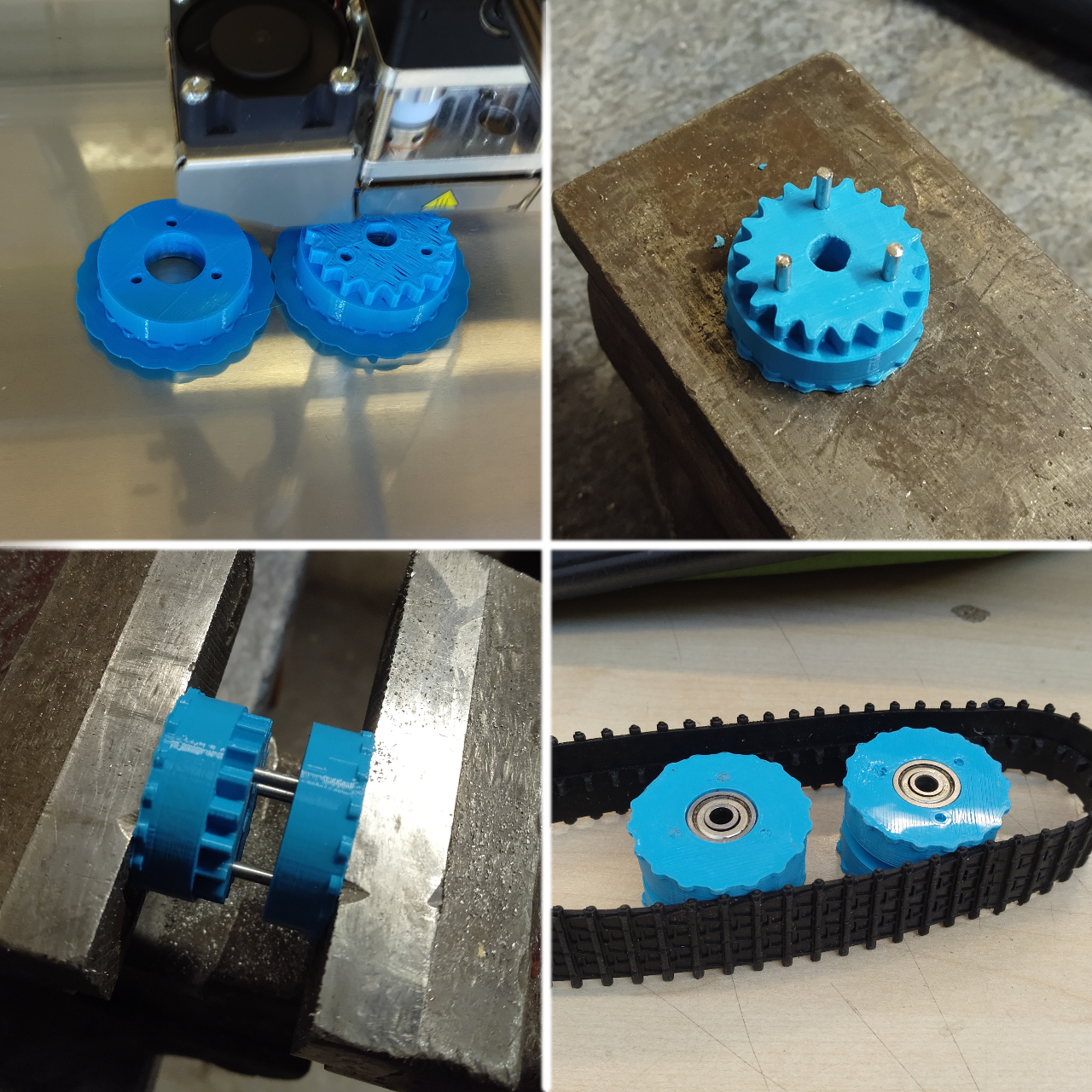
And so began a highly iterative process to try and derive the right dimensions for my pulley. It took me about 10 iterations on the laser cutter to find something that ran "well enough" - you'll see one gear below which has a different tooth profile - that just has the track tooth profile cut out of it - but of course the teeth bind horribly as they're wrapped around the wheel. That was the first attempt, and was rectified in the later designs.
I started with a fully laser-cut prototype, with no motor, no bearings - just layers of laser-cut wood mounted on bamboo skewers. I don't have any photos of it, but it gave me confidence that my pulley design was close enough, and that the overall size of the track was appropriate for the length of the rubber. (I don't have any photos from that... sorry).
Lasering was a quick way to iterate prototypes, but I decided to 3D print the pulleys for the "final" prototype.
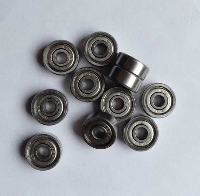
I got some small bearings from China on ebay. They're fine - except that they came lubricated with what appears to be thick treacle - honestly the bearings as delivered would barely turn. I had to guy and buy some acetone nail varnish remover (which cost more than the 30 bearings!), and clean them up. Now, they're pretty good.
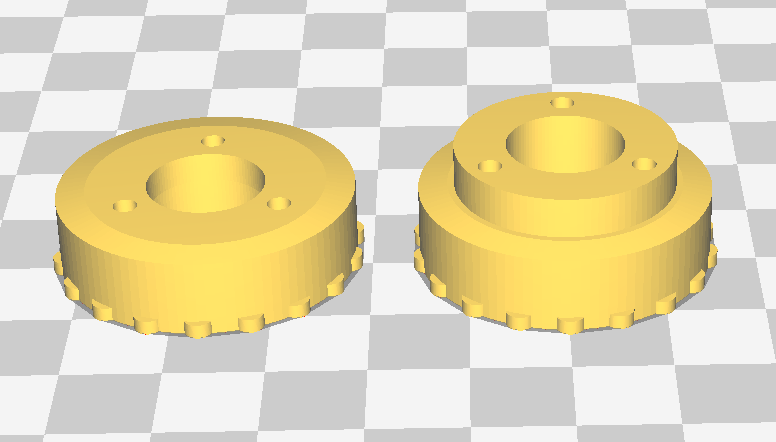
I drew up a pulley design in OpenSCAD, in two flavours - one without teeth for the idler wheels, and one with teeth and a hole for designed for the motor shaft for the drive pulley.
So I printed two idlers, and one drive pully - slightly tweaking the design after each one (drive wheel was last - as it has the important drive teeth and so needed to be the most accurate).
To avoid any overhangs, I print the wheels in two halves, and then connect the two together with some coathanger wire. The result is actually very secure, and the bearings sit in my bearing cups very nicely:
Mounting and Structure
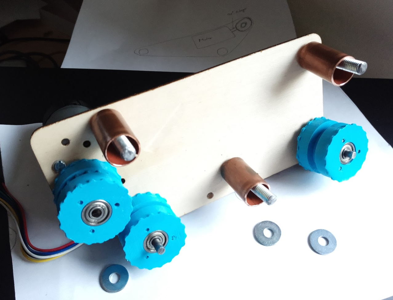
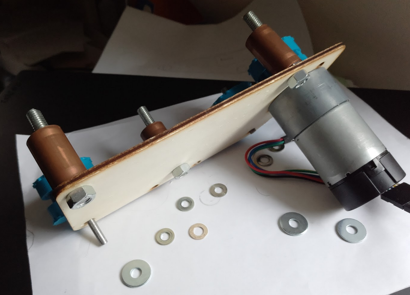
With pulleys done, I modified my plywood prototype to support the 4 mm rods (for the bearings) instead of 3 mm bamboo skewers, and to support some threaded-rod spacers. My M3 Nylon spacers are on a slow boat from China, so I've improvised using some copper pipe which I had to hand, which I've cut to the same 25mm that my spacers will be.
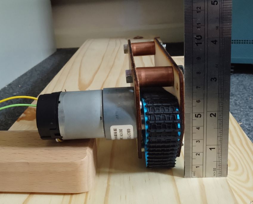
Finally, with the prototype constructed I could try plugging it in... and it works better than expected!
Running at 5V (final robot will be 3S 11.1V battery), the motor has really good torque. The tracks don't slip at all (at least at this voltage the motor stalls before they do). Also the exposed track at the front, and the very forward centre of gravity makes it really good at climbing obstacles.
Next Steps
Now I need to make a new pair of modules, with the final pulley design and properly designed side pieces (instead of ones that I hacked up a few times) - and probably I'll wait for my nylon spacers to do that so I can do away with the copper pipe.
-
Camera, Open GL ES and distortion models
08/27/2017 at 17:27 • 1 commentMy robot design uses a camera with a very very wide-angle lens. I bought a Pi camera module with a 175 degree wide angle lens which fits the bill (https://www.ebay.co.uk/sch/i.html?_from=R40&_trksid=p2054502.m570.l1313.TR0.TRC0.H0.X++Camera+Module+Board+1080P+5MP+175%C2%B0+Wide+Angle.TRS0&_nkw=++Camera+Module+Board+1080P+5MP+175%C2%B0+Wide+Angle&_sacat=0). It's not a Pi-foundation official one (which it seems the Pi foundation abhors so much that they put a cryto chip on the v2 module to stop people making knock offs https://www.raspberrypi.org/forums/viewtopic.php?f=43&t=149426#p982590. If there was an official 175 degree module, I'd have bought one).
175 degrees means that there's a decent amount of distortion in the image (fish eye style), which I want to get rid of so I can use the images for something useful. So, I need to undistort them.
![]()
OpenCV will end up in my image pipeline at some point, and it is able to correct lens distortion itself - but CPU power is really precious on the Pi (even the Pi3 - Cortex-A53 is a deliberately weak CPU as far as ARMv8 goes - it's designed for high efficiency, not performance). So, correction on the CPU doesn't look appealing - but we have got a nice OpenGL ES 2.0 GPU sat in the Pi which will be otherwise un-utilised in my robot - so let's kick that in for the lens correcion!
Step 1. Hello Triangle
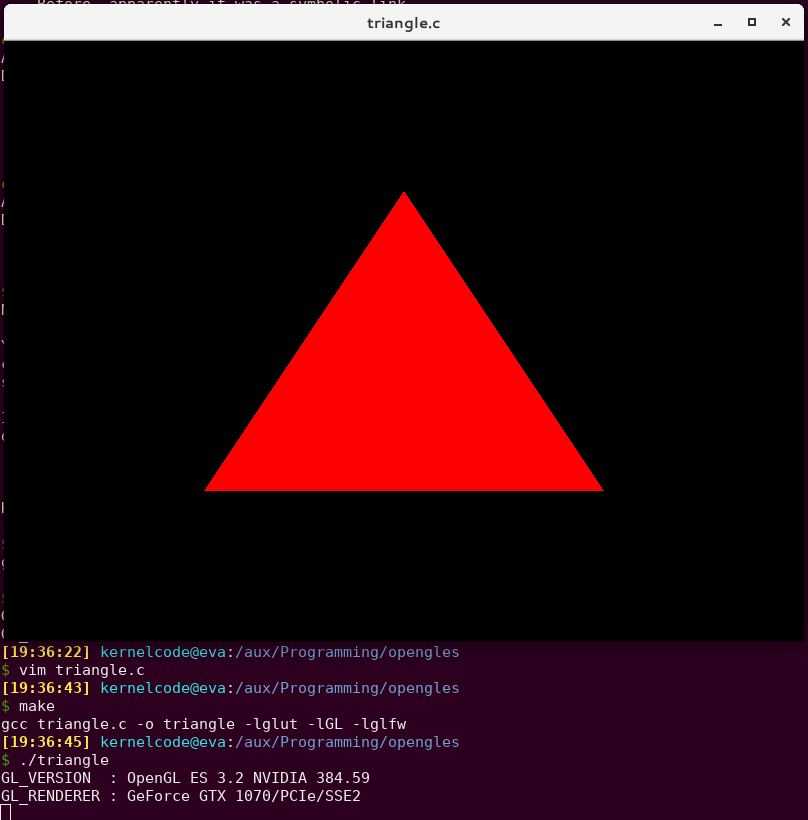
I don't know OpenGL ES. I'd never done any GPU programming in my life. So step 1 was to find the most basic Open GL ES example I could.
Thankfully, my friend Ciro Santilli had just what I needed - a tiny, self-contained "Hello Triangle" example in C: https://github.com/cirosantilli/cpp-cheat/blob/master/opengl/gles/triangle.c
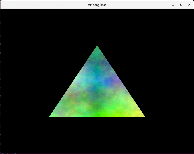
Fabulous! We can draw a triangle and we didn't even need to write any code yet!
Step 2. Textured Triangle
OK, so we can draw a triangle and fill it with a single colour. That's not much use in the real world - what we actually want to do is draw something onto the triangle. That's called texturing.
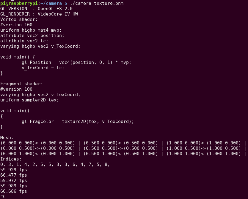
So my next step was to add some code to import images (using libnetpbm because it's literally as simple as you can get). Once you've loaded the image data into memory somewhere, you create an OpenGL ES texture with it, hook that up to the fragment shader - and voila:
Creating the texture:
glGenTextures(1, &tex);
glActiveTexture(GL_TEXTURE0);
glBindTexture(GL_TEXTURE_2D, tex);
glTexParameteri(GL_TEXTURE_2D, GL_TEXTURE_WRAP_S, GL_CLAMP_TO_EDGE);
glTexParameteri(GL_TEXTURE_2D, GL_TEXTURE_WRAP_T, GL_CLAMP_TO_EDGE);
glTexParameteri(GL_TEXTURE_2D, GL_TEXTURE_MIN_FILTER, GL_LINEAR);
glTexParameteri(GL_TEXTURE_2D, GL_TEXTURE_MAG_FILTER, GL_LINEAR);
glTexImage2D(GL_TEXTURE_2D, 0, GL_RGB, texture->width, texture->height, 0, GL_RGB, GL_UNSIGNED_BYTE, texture->pixels);
glBindTexture(GL_TEXTURE_2D, 0);
For the vertex shader, we add some extra code to emit a texture coordinate as well as a vertex coordinate:
#version 100
attribute vec3 position;
varying highp vec2 v_TexCoord;
void main() {
   gl_Position = vec4(position, 1);
   v_TexCoord = vec2(position.x + 0.5, -position.y + 0.5);
}
And in the fragment shader, we use "texture2D" to read from the texture:
#version 100
varying highp vec2 v_TexCoord;
uniform sampler2D tex;
void main()
{
    gl_FragColor = texture2D(tex, v_TexCoord);
}
Now we're well on the way - we now know pretty much everything we need to know in order to do our lens correction.
Next little stepping-stone is to add in some co-ordinate transformation so that it's a little easier to think about coordinates in our "scene". I added a projection matrix which changes the GL "normalised device coordinates" (which are -1 to 1) to plain normalised coordinates (0 to 1) and to flip the Y axis so that 0,0 is in the top-left (the same as literally everything else in the world except for OpenGL).
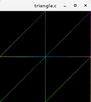
Step 3. Drawing and mapping to a mesh
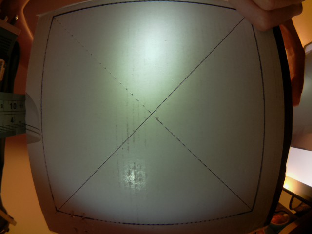
So, a single triangle is great - but we can't use just one triangle to do lens correction - we need a bunch of triangles which we'll then map on to the texture in such a way that it undoes the distortion added by the lens. The mesh will be created as a grid of pairs of triangles, which is pretty easy to do programmatically. Here's what a 2x2 mesh looks like (8 triangles):
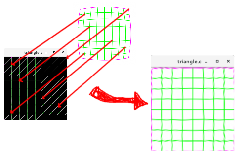
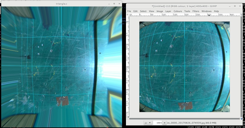
I used GIMP to draw a test grid pattern, and then used the "Lens Distort" filter to distort it somewhat - then (mostly) by hand I wrote down the pixel coordinates of each line intersection and put that look-up table into the code, I created a 9x9 mesh with my new mesh generation code, and mapped each of the line intersection coordinates from the distorted image onto each vertex in the mesh. The end result is a nicely undistorted image: Success!
Step 4. Lens Models
I spent a while after this researching programmatic ways for describing the lens distortion - hand-transcribing coordinates wasn't something I was planning to do again.
There's a few different algorithms and methods (Brown's Model is a popular one for describing lens distortion). There's also software tools already which do the correction for you - Hugin is one of them, and it's mean to be able to figure out the "distortion parameters" of your lens - but I couldn't get it to give me any meaningful numbers.
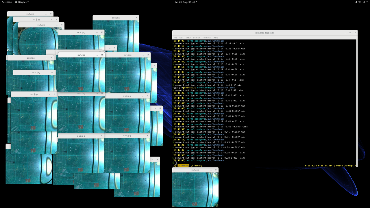
I spent a long long time running ImageMagick on a photo from my camera and just fiddling with the parameters until it looked "OK":
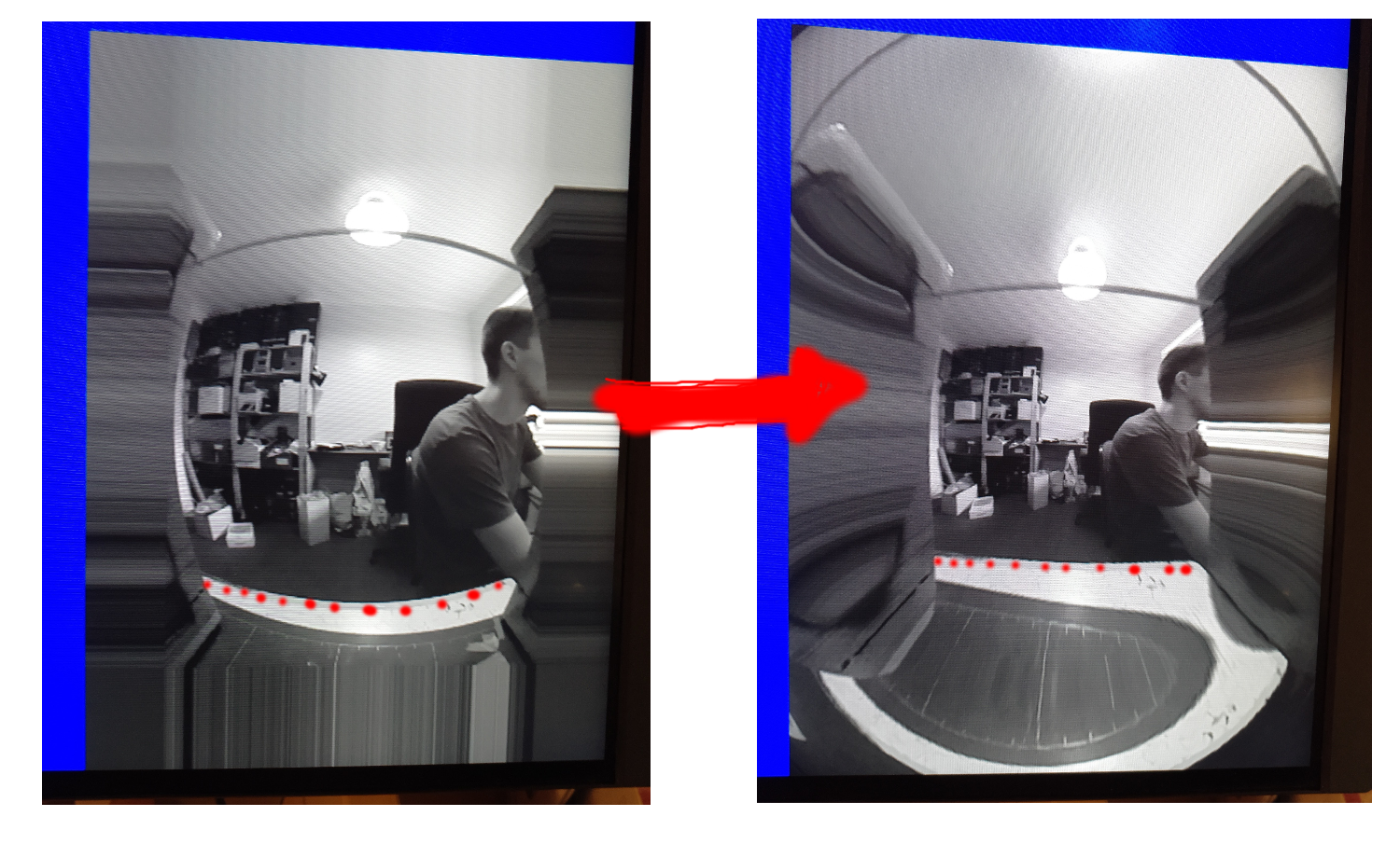
Some more code later and I was able to correct one of my camera stills pretty satisfactorily (bendy lines on the right - straighter lines on the left):
It's perhaps worth clarifying at this point, that I'm not calculating the distortion itself on the GPU. At application start up, I calculate a mesh, and a texture co-ordinate for each vertex in the mesh - the GPU then just does a simple sampling using these coordinates. This is more efficient - pre calculating the mesh only needs to be done one, and the GPU does basically no calculation in the shaders.
Step 5. Porting to the Pi
The more eagle-eyed readers might have spotted already that so far I've been running everything on my NVidia desktop card. Now I had something worthwhile I set to porting it to the Pi.
Ciro's original code was using GLFW to interface with the operating system - this gives us a window to draw in. On the Pi, we're instead going to use the Pi's EGL implementation to talk to the display hardware more-or-less directly. The Pi ships with some simple examples in /opt/vc/src/hello_pi, so I just nicked all of the setup code from one of them, and wrapped that up in a tiny little abstraction that lets me run on both the Pi and my desktop. The abstraction has only three (four) functions:
struct pint {
    void (*swap_buffers)(struct pint *);
    bool (*should_end)(struct pint *);
    void (*terminate)(struct pint *);
};
extern struct pint *pint_initialise(uint32_t width, uint32_t height);
I split out the GLFW code from my existing source, and implemented the new abstraction in both GLFW and the Pi EGL interface.
After a little compiler back-and-forth I had the same code running on the Pi - and was relieved to see that it was running just fine at 60 FPS! (Not too surprising given that the GPU is doing naff all).
Step 6. Texture fast-path
OK, so now the last piece of the puzzle is to actually get data from the camera instead of my wimpy libnetpbm imports.
One way to do this is to capture from the camera to a memory buffer (like raspistill does), and then upload that to a texture, and then use that in the GL shaders, just like with the PNM images. The problem is, this is slow. You have to copy all the data from the camera into a buffer somewhere, then you have to upload that to the GPU (which probably involves a format conversion into some internal format for the GPU), and you have to do this every frame. Remember the whole point of this exercise is to leave the CPU as idle as possible to be used for other robot business.
Luckily, the Pi multimedia stack has a direct-to-texture path from the Camera to the GPU. This is implemented via EGLImage and the OES_EGL_image_external extension.
Raspistill has some example for how to make this work, and I found SanderVocke's minimal example, which basically takes the Raspistill code and distils it down to the bare minimum. I used SanderVocke's code as my starting point.
It boils down to a fairly small number of changes from what we had before. Firstly, instead of creating the texture from data in memory, you use a special texture type, and some EGL magic:
glBindTexture(GL_TEXTURE_EXTERNAL_OES, tex);
img = eglCreateImageKHR(GDisplay, EGL_NO_CONTEXT, EGL_IMAGE_BRCM_MULTIMEDIA_Y, (EGLClientBuffer) buf->data, NULL);
glEGLImageTargetTexture2DOES(GL_TEXTURE_EXTERNAL_OES, img);
Instead of binding GL_TEXTURE_2D, we bind GL_TEXTURE_OES, then we create an EGLImage with the Pi-special target "EGL_IMAGE_BRCOM_MULTIMEDIA_Y" - this tells EGL that we want to get the "Y" (luminance) plane from the buffer, and create an EGLImage from it. Lastly, we tell EGL to target that image at the texture.
Secondly, in the fragment shader, instead of using a normal "uniform" for the texture, we have to use a special type to use the external image as a texture:
#version 100
#extension GL_OES_EGL_image_external : require
uniform samplerExternalOES tex;
varying highp vec2 v_TexCoord;
void main()
{
    gl_FragColor = texture2D(tex, v_TexCoord);
}
and lastly, in between each frame of rendering, we have to dequeue a new buffer from the camera:
glUseProgram(shader_program);
glUniform1i(texLoc, 0);
glUniformMatrix4fv(mvpLoc, 1, GL_FALSE, mat);
glActiveTexture(GL_TEXTURE0);
/* Wait for a new frame from the camera */
while (!camera_read_frame());
glBindBuffer(GL_ARRAY_BUFFER, mesh->mhandle);
glBindBuffer(GL_ELEMENT_ARRAY_BUFFER, mesh->ihandle);
glDrawElements(GL_TRIANGLE_STRIP, mesh->nindices, GL_UNSIGNED_SHORT, 0);
pint->swap_buffers(pint);
An hour or two of fiddling later, and I finally had a live video feed on my Pi's monitor. Some things to note are:
- You must wait until you have a frame from the camera before you call eglSwapBuffers()
- That's what the while() loop is for on camera_read_frame(). Without this, it crashes within a couple of loops
- You must shut-down the camera correctly - otherwise it locks up and you can't use it again until you reboot
- I must say that's some pretty shoddy design/implementation on the Foundation and/or Broadcom. If the process dies, they should clean everything up appropriately, in my opinion.
One Weekend Later
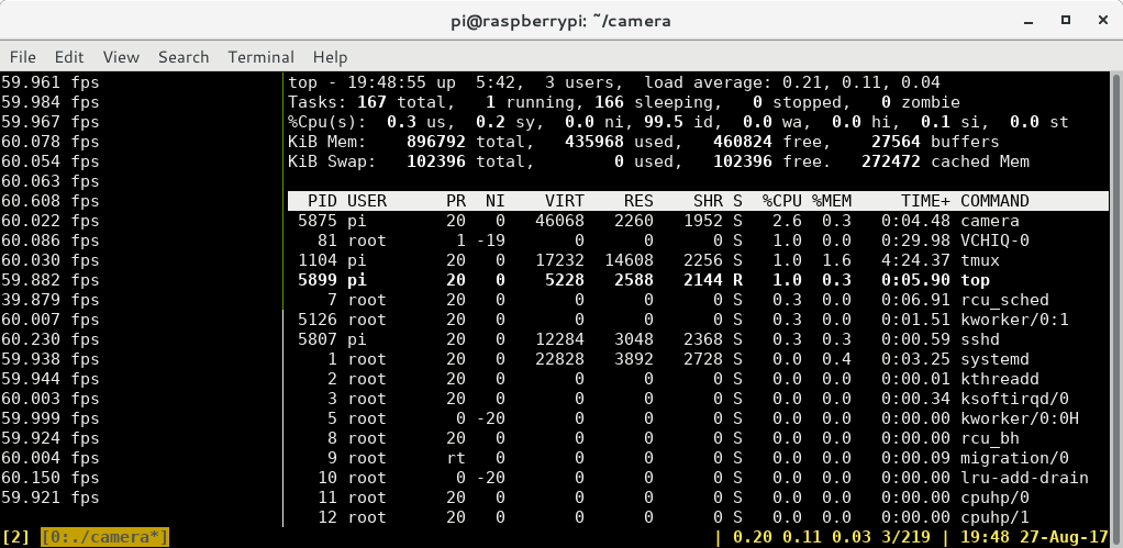
All right! So, after all is said and done, I now have the camera hooked up to some GL code, I can (mostly) undistort my images at 60 FPS, and the Pi CPU consumption is less than 5%. I'd say that's a win for a weekend's work!
Drawing top in tmux over SSH is almost consuming as much CPU as my camera application at 60 FPS!!
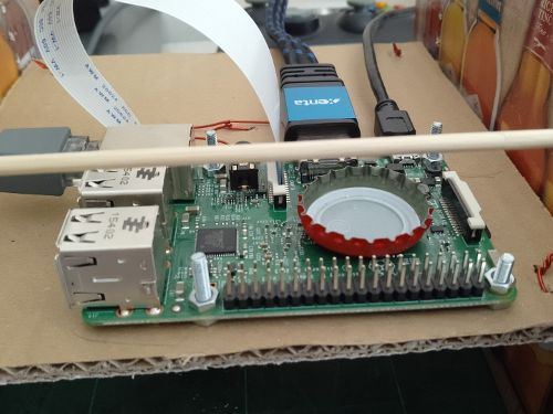
It might not be a significant CPU load, but I did notice the Pi was getting pretty warm (it's quite a warm day) so I had to lay a bottle cap on the CPU to help cool it down
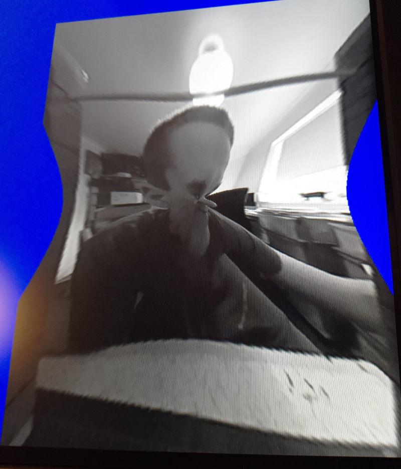
Also what good is writing a camera shader application without a few silly alien pictures?
Next Steps
So, I've got most of the building blocks I need - what's next for the camera subsystem?
- I will probably switch back to some form of hand-generated mesh for the distortion parameters, I think I can get a better result this way - and given I only have one camera in one position to deal with, it's not a huge overhead to do it once.
- Get the output from the camera shader into the program!
- So far all I've done is display the image. That's not much use for actually using the camera for something. So I need code to export the image. This is going to be a significant CPU hog - so I need to reduce the image size(s) as far as I possibly can before I read it off the GPU
- Moar processing!
- I probably want to do a bit more processing of the image in OpenGL before I get it out. I expect I'll do some kind of thresholding and perhaps a blur to give me some nicer input to OpenCV - as with the distortion, OpenCV can do it itself - but it should be a lot cheaper in terms of CPU time to do it on the GPU
- RGB output
- In my system, I need two outputs from the camera: One for OpenCV (luminance will do fine for that), and one that RGB for looking at. So I need to write another shader to convert YUV to RGB.
- You must wait until you have a frame from the camera before you call eglSwapBuffers()