Richard Dudley
-
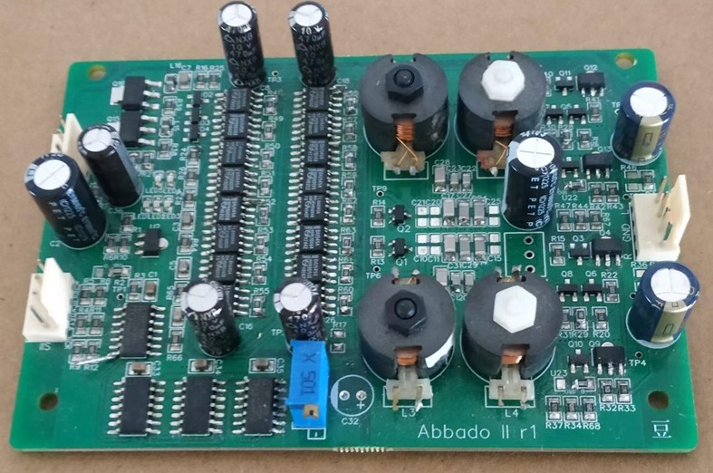
Abbado II DAC
05/19/2024 at 02:42 • 0 commentsAbbado II is my first design to make use of the TDA1545. The reason for the swap of DAC chip I explained in my last log entry - 1545 offers more output current for slightly less supply current. Thus it requires fewer chips and less power to achieve the same SNR as TDA1387.
Abbado II has a slightly modified 'rear end' (meaning I/V and output stage) compared to earlier designs which allows it to operate from a lower supply voltage (9V) - this choice is more economical on power. It is also simpler and contributes less noise due to the removal of one biassing current source. The change to the back end is facilitated by shifting the supply rails to the DAC chips so that their 0V pins hang 'in mid air' between the power rails, their 5V pins connect direct to the 9V rail. The regulators feeding the DACs therefore operate on the negative rail. Because the 0V pin is also the reference for the digital input signals, there is need for some level shifting and I do this in the cheapest (and electrically fastest) way possible - with series capacitors. The capacitors have to be kept charged to +4V, done with the help of clamping schottky diodes. TDA1545 with its slightly unusual input format needs a couple of shift registers to allow Abbado to be fed with the industry standard I2S digital audio format.
Abbado II has a 5th order LC filter for reconstruction duty which takes up a fair amount of PCB space due to the bulk of the P14 inductors. Such a filter approaches a textbook anti-imaging solution when fed from a 2X upsampler - the first image frequencies in 2XOS occur at 68.1kHz and the Chebyshev filter delivers just over -70dB attenuation there.
![]()
The output stage remains the SE classA design tried and tested from earlier DACs - this time though there's a resistor selection of output gain to make balanced mode operation a little easier to accommodate. Typically a balanced DAC will output twice the voltage level, on Abbado its possible to attenuate that back to the same level as unbalanced. Balanced mode requires an I2S splitter board to generate the true/anti-phase signal pair for both L and R and calls for two Abbados. The blue trimmer in the picture allows the gains of L and R channels to be closely matched.
-
TDA1387 and TDA1545A
05/29/2023 at 05:05 • 0 commentsI've decided to abandon DAC development with TDA1387 after a decade or so of interesting designs using it and instead, go over to TDA1545A.
The reason is - TDA1545A offers better bang-for-the-buck in designs with more than a half-dozen or so paralleled chips. The key metric of interest for a DAC chip is SNR and by virtue of its 2mA maximum output current the 1545 delivers better numbers in this regard than the 1mA 1387. The 1387 can of course be 'overclocked' (I have gone up to 1.5mA) but so can the 1545. What's more, the 1545 delivers its output current at the cost of slightly less supply current. When paralleling large numbers (many dozens) of overclocked 1387s in a small space, heat dissipation became a significant problem, calling for a cooling fan. Using 1545 relaxes the thermals somewhat.
TDA1545A's downside is its use of a right-justified input format rather than I2S so it eats up 2 or 3 more logic chips converting from I2S to its native format. For this reason, 1387 is still the best choice for an entry-level design like Toscanini. Moving ever onward, I have been working on a design with 16 paralleled TDA1545A which is sounding excellent and that'll be the subject of the next log entry.
-
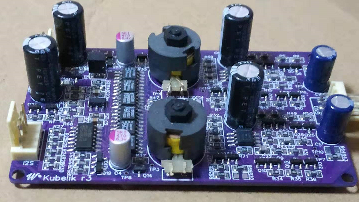
Toscanini
12/13/2022 at 07:59 • 0 commentsToscanini is an upgrade to Kubelik. Once I discovered that TDA1387s can be 'overclocked' I wanted to incorporate overclocked chips in a DAC, Toscanini is it. Toscanini runs from a lower power supply voltage - ignore the +20V on the silkscreen, its an error. As a result gives up the ability not to clip during inter-sample overs. It's a little more 'green' (not just because of its PCB colour) in energy consumption.
Here's the first prototype :
Image filtering is 3rd order just as with Kubelik and Dorati but the inductors can be sourced from Mouser in a couple of forms, either SMD or TH. -
Replacement for Kubelik - introducing Dorati
05/07/2022 at 12:43 • 0 commentsSeveral dozen Kubelik kits have been sold now but when we came to re-stock some of the components for another batch we found the price of the opamps has gone up threefold. This is rather off-putting as they were the most expensive single item after the PCB and filter inductors. I became curious to discover how essential the opamps are in the scheme of things and whether a re-design to avoid them would have significant drawbacks. Certainly measurement-wise their application of lots of loop gain keeps the Sallen-Key unity gain buffer used for droop correction very low distortion. Experimenting shows sound quality does not suffer, its been clear for a few weeks now that if anything there's a subjective improvement from their elimination.
One customer managed to connect his Kubelik power supply backwards and, naturally enough his DAC died from that kind of abuse. As a result of helping him to get it going again I got him to remove the opamps and apply some wires to bypass them. He did eventually get sound out which says that everything but the opamps survived the polarity reversal. I can't help but think a DAC minus opamps would be more robust against simple DIY finger trouble.
Seeing as passive I/V (as mentioned in an earlier log) proved to be lower noise than active, it follows there's no need for the first stage opamp, just a unity gain buffer to 'stiffen up' the output. The SE OPS already employed acts as a unity gain buffer so why not just use that without opamp assistance? Yes there'll be second harmonic distortion but that is normally subjectively benign. Sallen-Key filters also can be built with emitter followers for the buffer stage so not a big deal. What's the challenge is - with DC coupling the voltage shift through two stages is a rather daunting 2.4V which might be a problem for managing signal headroom. The alternative would be AC coupling which would call for an extra pair of coupling caps between stages. The best cap is no cap so it was worth aiming for DC coupling to see what turned up.
Headroom is something to pay attention to, not just because of the DC shift. The LC filter has some peaking on its output, about 2dB according to simulation and this occurs at or near the corner frequency (~17kHz). So 25% extra swing is needed at the cascode MOSFET output. The final stage - the Sallen-Key filter used primarily for droop correction - is a major contributor to the noise due to the input resistors and the positive feedback at higher freqs. In simulation, above 10kHz or so the noise roughly doubles. The choice of Rs has the biggest impact on the noise, I wanted to use the lowest impedance commensurate with being able to drive the input without gobs of current demand in the preceding buffer stage. In the end I settled on 470ohm for Rs and this results in 32nF for the feedback cap, something achievable without too high a footprint penalty - two paralleled 0805 NP0s.
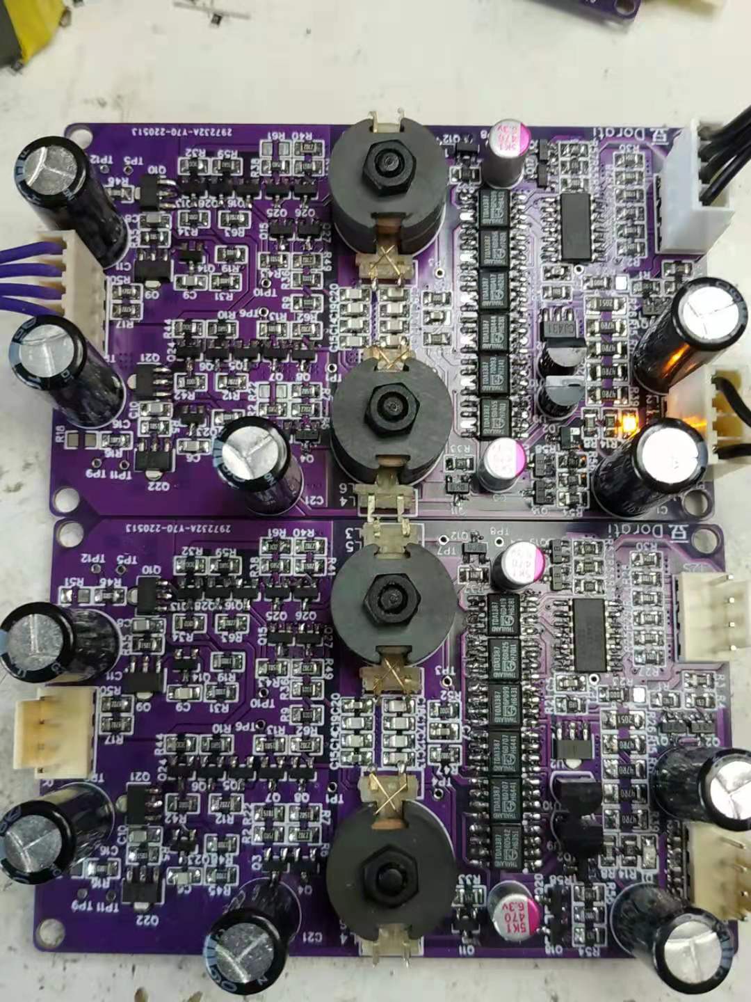
Having built up and listened to a couple of prototypes, I feel confident this new design comfortably beats its predecessor, though quite why I'm not totally clear on. The SNR of the post-DAC stages has gone up about 5dB but even on Kubelik the number was extremely low for a 16bit DAC - in the region of -124dB. Schematic to be posted up once component values have been finalized over a handful of builds.
![]()
Two of the earliest prototypes of Dorati, there's a difference in the resistor values in the S-K filter, just to explore whether that's audible.
-
Next generation Kubelik - Abbado
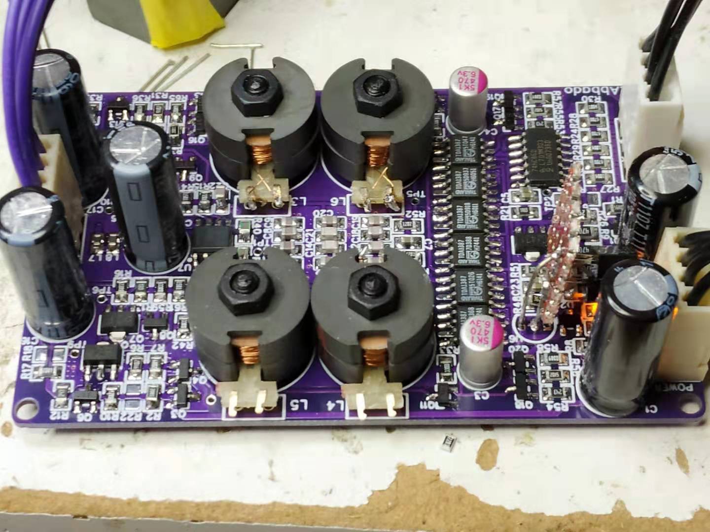
04/06/2022 at 09:35 • 0 commentsHere's the evolution of Kubelik based on my investigations into why Kubelik lost out in dynamics in comparison with Deca DAC.
![]()
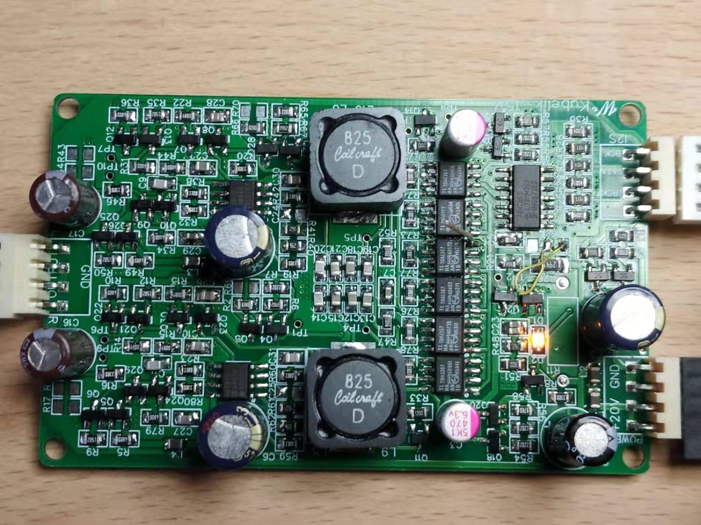
The filter now uses two inductors per channel, beyond the filter there's now passive I/V with a unity gain buffer following. The bias to the output stage can be rich enough to drive high impedance headphones (150ohm and up) directly by virtue of beefed-up output transistors (SOT-89). So a neat solution for a DAC-amp. This can be purchased in built-up form, no kits as the caps in the filter need to be hand-selected. -
Moving beyond Kubelik
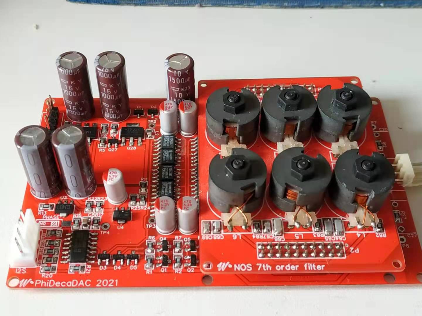
04/05/2022 at 13:49 • 0 commentsIn a side-by-side comparison between Kubelik and Deca DAC, the latter wins out on dynamics, especially in the bass. I was very curious to find out what was going on to reduce the dynamics in Kubelik.
First up I figured the filter might be the primary reason - Kubelik has a very simple, 3rd order (CLC) filter whereas Deca has a complex 7th order one. So I built variants of Kubelik with higher order filters, firstly 5th order then 7th order. These needed piggy-back PCBs on which all the extra inductors were mounted. Not a pretty sight!
Results were that dynamics did improve but even the 7th order version of Kubelik didn't reach the levels of Deca DAC. So then I wondered if it was down to the opamp I'm using (OPA2209). I bypassed that, feeding the SE output stage directly from the I/V resistor - hence 'passive I/V' rather than active, just for the hell of it. Wow, a very large improvement - much more engaging sound! The level of improvement was very surprising.
So was the lack of dynamics the opamp's fault? I decided it needed a 2nd chance, so I brought it back in, this time as a buffer rather than in inverting ('transimpedance') mode as is traditionally used for I/V. The engagement factor stayed. Hmmm.
In simulation it turns out that the output impedance of the filter interacts with the opamp to increase the noise gain at certain frequencies with a traditional I/V stage. With passive I/V, the opposite happens - the noise gets reduced at those same frequencies. Seems like this is a plausible reason for the improvement in dynamics going from transimpedance to passive I/V. So then I wondered how much control I had over the frequencies where the noise was being reduced. Naturally, it depends on the filter and I found a 5th order filter had potential to reduce the noise close to the most sensitive range of our hearing (3 - 5kHz roughly). The Fletcher-Munson curves for our hearing thresholds vs frequency have a noticeable dip in that region. However, for some reason I also turned up ITU-R468 which is more relevant for noise (F-M is based on a single tone). In that standard, the peak of the weighting curve is a bit higher in freq, just over 6kHz.
I wondered if I could design a filter which gave the lowest noise in the vicinity of 6kHz. From fiddling with the Chebyshev online filter designer (https://rf-tools.com/lc-filter/) the dip in the noise turns out to be a function of the ripple of the filter, not just the cut-off frequency. Going higher ripple allowed me to place a dip in the noise gain very close to 6.3kHz.
-
Introducing Kubelik
01/01/2022 at 11:14 • 2 commentsMy first incarnation of the 'Kubelik' design, using the architecture I set out in the previous post used a single TDA1387 DAC chip. Listening to this, it turned out to have a very engaging improvement in transparency over 'PhiDAC' - there was that sense of 'air' or 'bloom' which created an impression of an acoustic bubble between and behind the speakers. However while the HF was very good, overall I felt the sound was too unbalanced top-to-bottom, there wasn't sufficient 'presence' in the bass, a lack of spaciousness at the lowest frequencies which help depict the acoustic signature of a hall or recording studio. The overall effect is the presentation sounds a little thin.
Increasing the number of chips to 3 did bring about improvement at the low end but it wasn't until I reached 6 chips that I felt there was a balance top-to-bottom, no more thinness. Going to more chips than six wasn't practical for a couple of reasons - there wasn't sufficient PCB space within the original confines of PhiDAC and also the dropping resistors (from 20V down to ~5V) couldn't be accommodated. In the end, thermal constraints restricted the DAC's supply voltage to 4.5V. Paralleling chips improves the signal-to-noise by 3dB for each doubling, so with 6 chips we have almost 8dB lowering of the noise and this reduced noise floor is most apparent in the bass. I'm guessing this bass-lightness of a stand-alone chip stems from it being CMOS where 1/f noise corners are rather notoriously high.
![]()
I have a BOM, schematic and gerbers which I'll upload in due course. They're already available on the DIYA thread but its a long one to navigate. Kits may be ordered too.
Listening to Kubelik in comparison to DecaDAC, the latter sounds distinctly blurry in the higher frequencies relative to Kubelik, however it does have the edge in bass performance. Whether that's down to lower noise opamps or a lower noise DAC PSU remains to be seen.
-
PhiDAC reloaded
06/16/2021 at 03:04 • 0 commentsAs the original PhiDAC dates back to 2019 and I've learned a little in the intervening time I was curious to see whether the design could be revisited.
First up - the AD8017s I have discovered are noisier than I had thought due to my ignoring the -ve input current noise contribution. They are also a bit limited by the upper supply voltage of 12V. After attending to some discussion on DIYA I wanted to see if I could build in some headroom for handling 'intersample overs' - there was none on the original PhiDAC due to the relatively low supply voltage.
TI have recently introduced some very nice (at least on paper) low-noise FET input opamps, in particular the OPA1656 and OPA1678. The latter appeals especially because its ultra-cheap. The design trade-offs with these opamps are rather different than with CFB types - their voltage noise is higher but there's no current noise to speak of so resistor values can go higher with only the resistor noise itself to be concerned about and not the opamp current noise into that resistor.
With higher working impedance the inductor(s) in the filter need to be higher value, so I have to wave goodbye to those 0805s as their inductance doesn't go high enough. P14s look to be a reasonable choice as I can get them in better tolerances than even the 5% Fastrons from a local manufacturer. Fastrons can be a useful fallback.
Higher working impedance means higher voltage swing at the DAC output - on PhiDAC the output swing was negligible as the filter impedance was ~33ohm. On this design I decided to use a 'cascode' MOSFET (aka common-gate stage) on the DAC's output - the output compliance then is limited by the breakdown voltage (and dissipation) of the FET. A 2N7002 is good to 60V but we won't need all that as opamps peg out around 36V typically. The cascode also means no level-shifting circuitry is needed on the DAC itself.
Noise and noise-gain simulations have revealed that the MFB type output filter I'm using isn't the quietest - a Sallen-Key design shows lower noise gain for the opamp and hence should be lower noise in practice.
Several listening experiments revealed that higher filter impedances made for a more dynamic sound - these listens though were done on the 'Deca DAC' with its bipolar opamp and multiple paralleled chips. With higher resistor values there is a limit to how much current we want from our DAC chips before we exceed the standard 2VRMS signal level. The OPA chips have an inherent voltage noise roughly equivalent to a 1kohm resistor so going lower than this seems counter-productive in the I/V stage - this sets an upper bound of 6 chips as 6mA*1k gives 6V peak-to-peak output. As to the lower bound, I was curious to hear how a single chip sounded so I built a single TDA1387 prototype for a listen. I'll report on that in the next log.
-
Phi DecaDAC - multi-multibit DAC for 2021
12/28/2020 at 04:24 • 1 comment![]()
Here is the latest incarnation of PhiDAC - by now it must be the 4th generation. This incorporates the latest discovery about noise in the I/V stage - on paper the analog stage is at least 12dB quieter than the 3rd generation PhiDAC. This translates into a wider soundstage (especially at the rear) and for some reason superior dynamics in the bass.
-
Further insight into paralleling DAC chips
12/02/2020 at 04:33 • 0 commentsAs one of my half-finished DAC projects involves a very large number of chips (72 minimum) I wanted a way to test individual DAC chips by listening before incorporating them into this design. So I designed and built a test board which accepted a single chip in a ZIF socket. I was shocked that this had more air and ambience apparent than the original PhiDAC (which also had a single DAC chip). My curiosity was piqued as previously I'd associated more ambience with more paralleled DAC chips. That is I thought I was lowering DAC noise by putting more chips in parallel, but this experimental single chip DAC threw a wrench in that hypothesis.
Turns out that the I/V stage noise is far more critical than I previously believed - it needs to be better than the DAC chip's noise by a significant margin to release the full amount of recorded bloom. In the original PhiDAC I am using AD8017 preceded by a very low impedance passive filter (~33ohm). Its this combination of low impedance with the AD8017 which contributes noise and masks the low-level ambience. AD8017 being a current-feedback opamp has significant current noise at its -ve input and that is associated with a not-very low noise corner. AD829 as on PhiDAC hex does quite a lot better - similar voltage noise but lower current noise which allows for a higher impedance passive filter. Seems with 6 chips and AD829 that 47ohm is a bit on the low impedance side, 100ohm is closer to optimum. Of course there's a trade-off in going higher impedance - more voltage swing at the DAC chip output pins. 6mA into 100ohm is 600mV but the filter 'rings up' near the corner frequency resulting in about 5dB peaking so worst case just over 1V swing. TDA1387 lacks an AC compliance spec (TDA1543 gives 25mV) - its best to keep this as low as possible, how low really can only be determined by listening. When I went up to a 240ohm filter the SQ wasn't as good so 100ohm is about the sweetspot with AD829.An alternative chip for I/V is LT1028 which has >6dB noise improvement over AD829 in its voltage noise and so is better suited to the existing 47ohm filters. Changing the filter impedance is rather inconvenient since I have already a large stock of inductors for the existing design and would need to commission more values. Thus changing to LT1028 is the best way forward for now - the fact that it doesn't have the OPS stage bypass matters much less than the improvement gained from lower noise.
Audiophile-sounding DAC for almost no money
0DAC - delivers engaging, immersive sound with a pricetag at least two orders of magnitude from commercial audiophile DACs