Richard Dudley
-
PCBs for 0DAC
04/05/2018 at 03:51 • 9 comments![]()
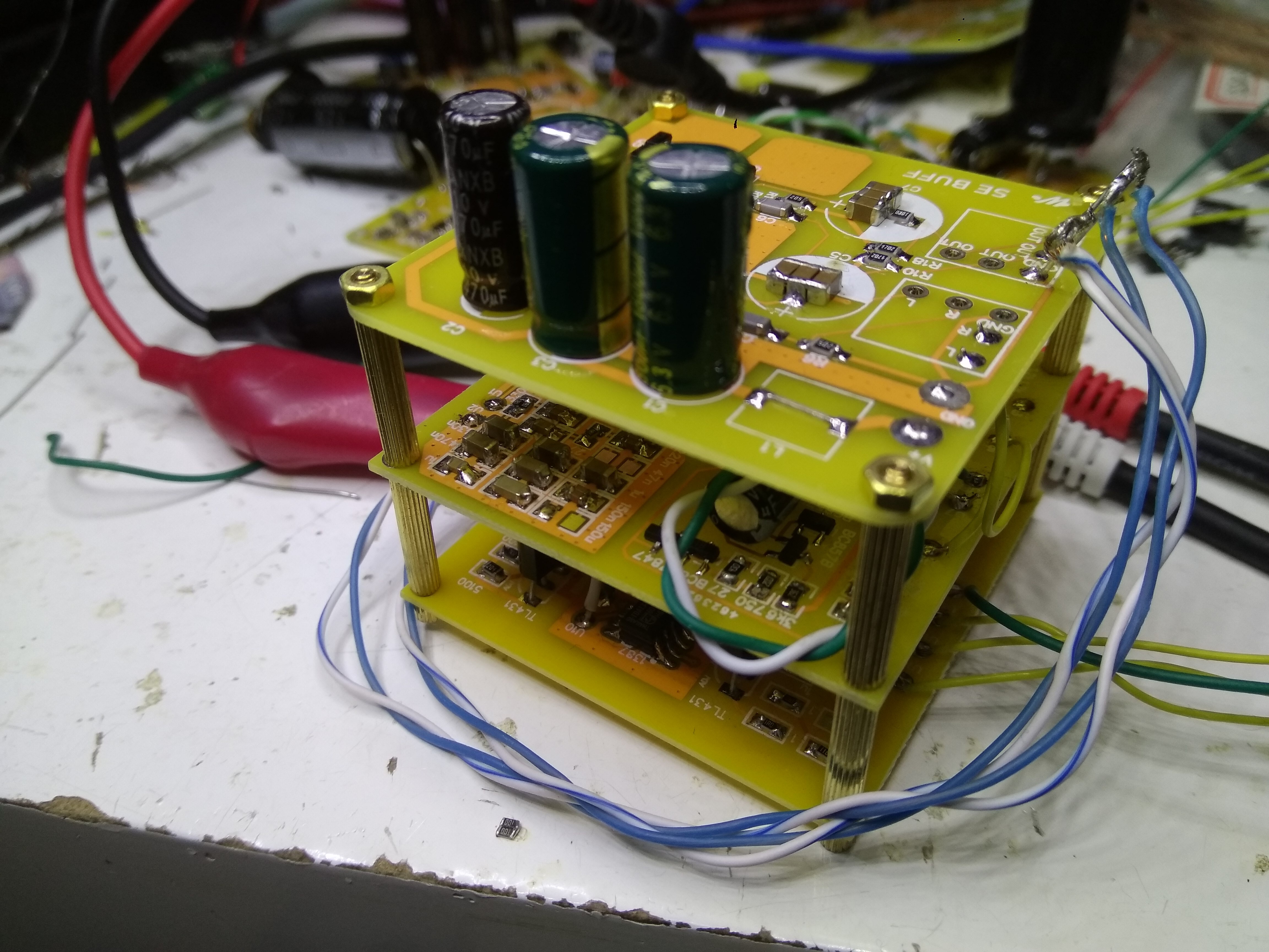
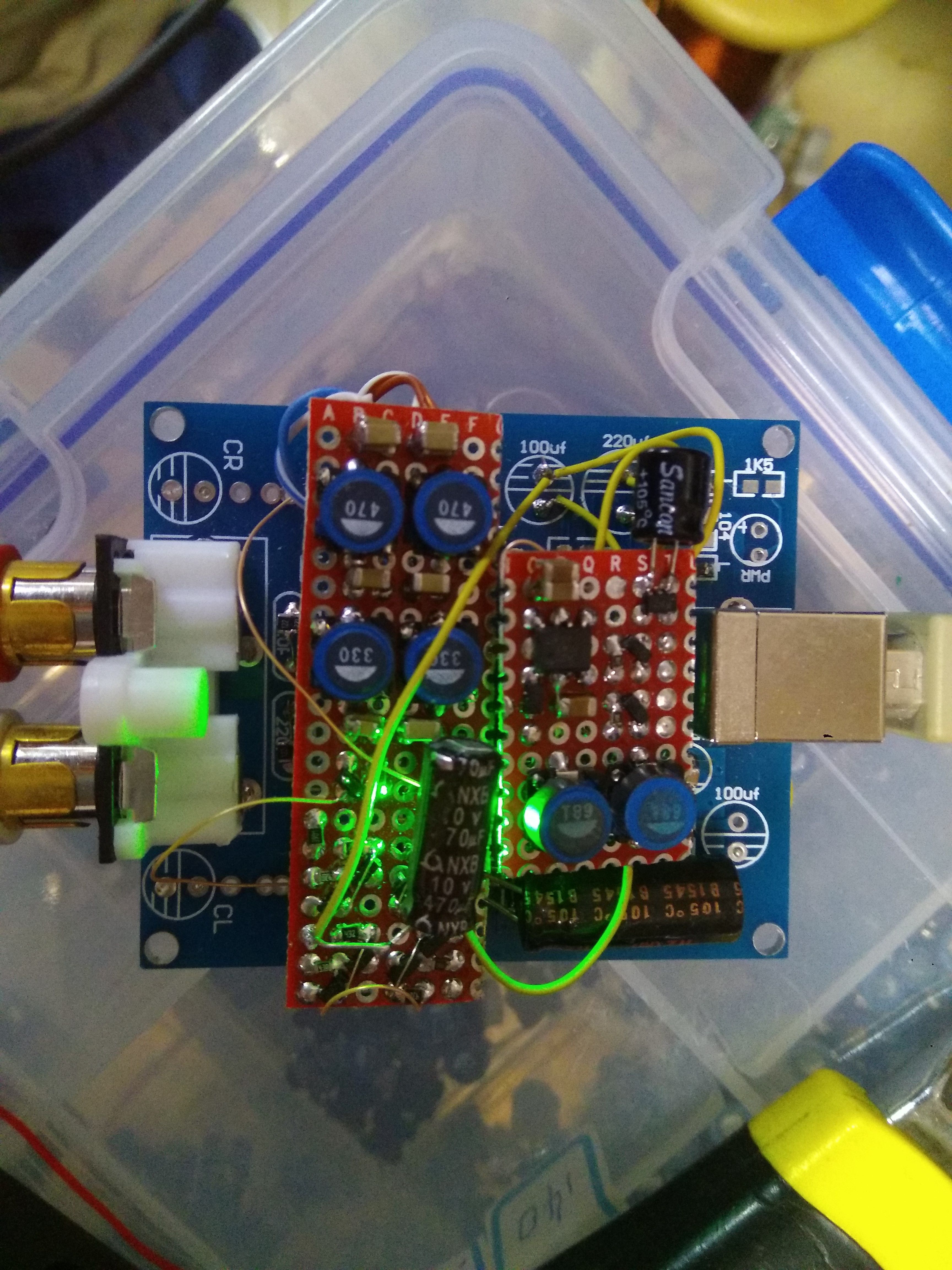
I now have some second generation prototypes built up, using PCBs kindly laid out by my gf. In this picture, the 0DAC is built from a stack of three boards. On the bottom we have the DAC and PSU, middle tier has the filter and I/V stage and at the top there's a buffer. The buffer can be implemented to drive headphones though the power supply might need to be external then due to heating concerns.
Here are the boards individually :
![]()
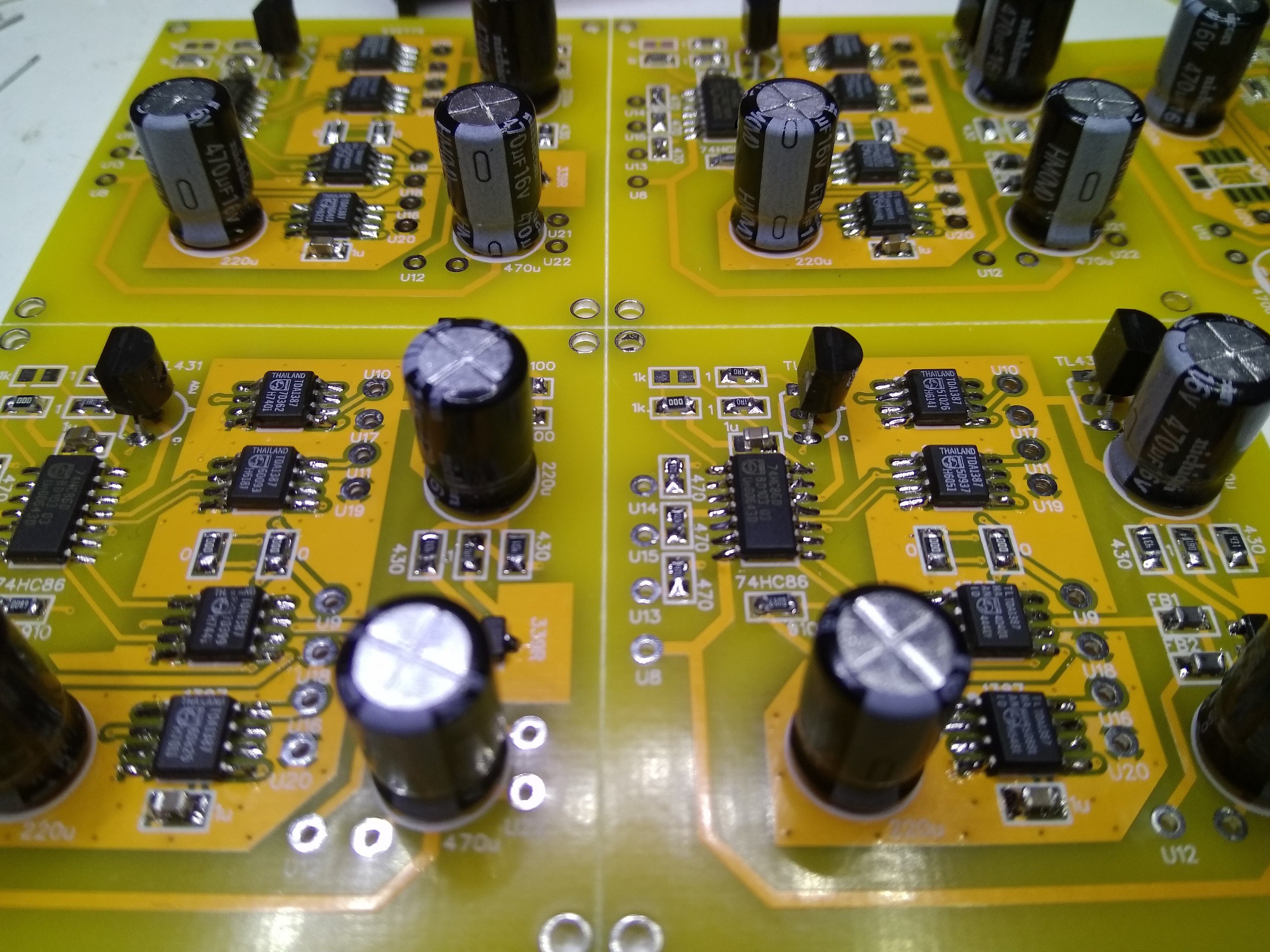
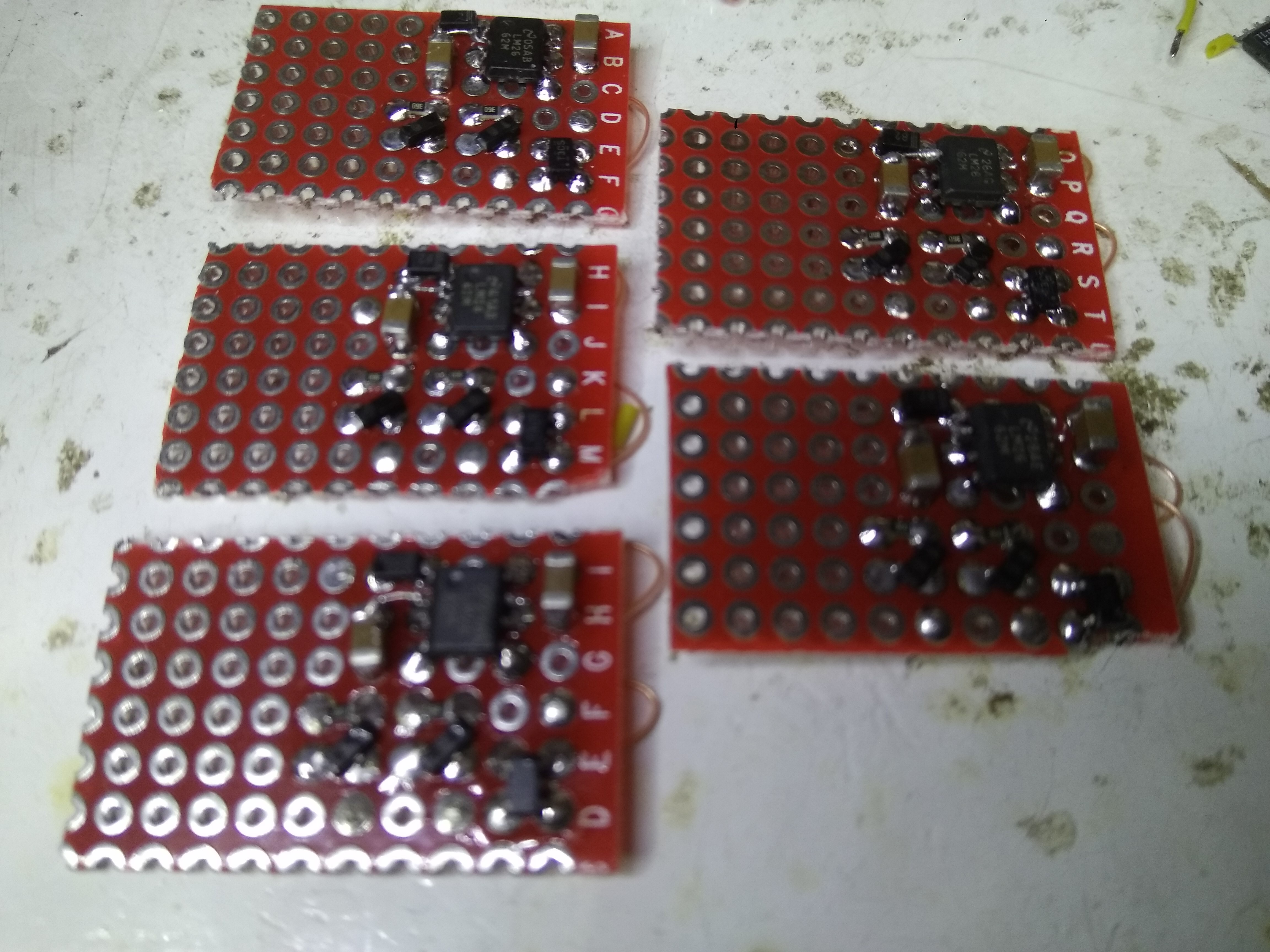
DAC board with 4 * TDA1387 and input buffer (HC86) and a simple PSU (TL431 and pass transistor)
![]()
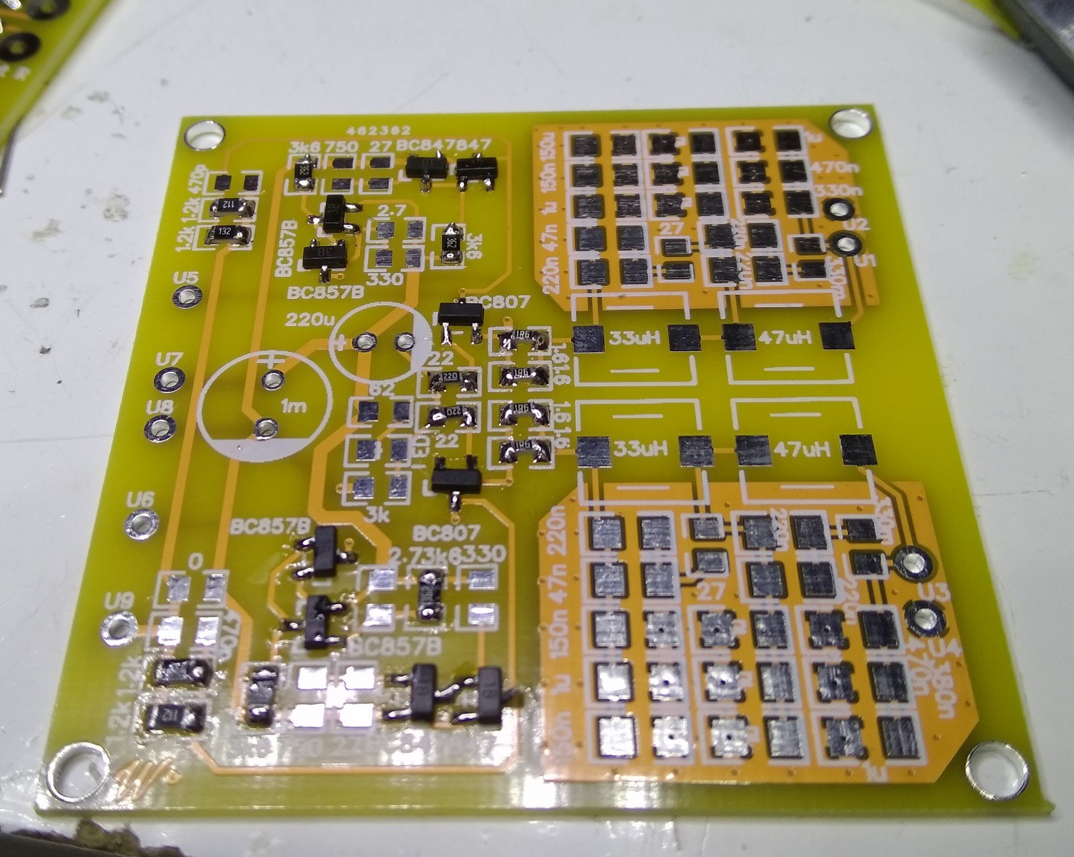
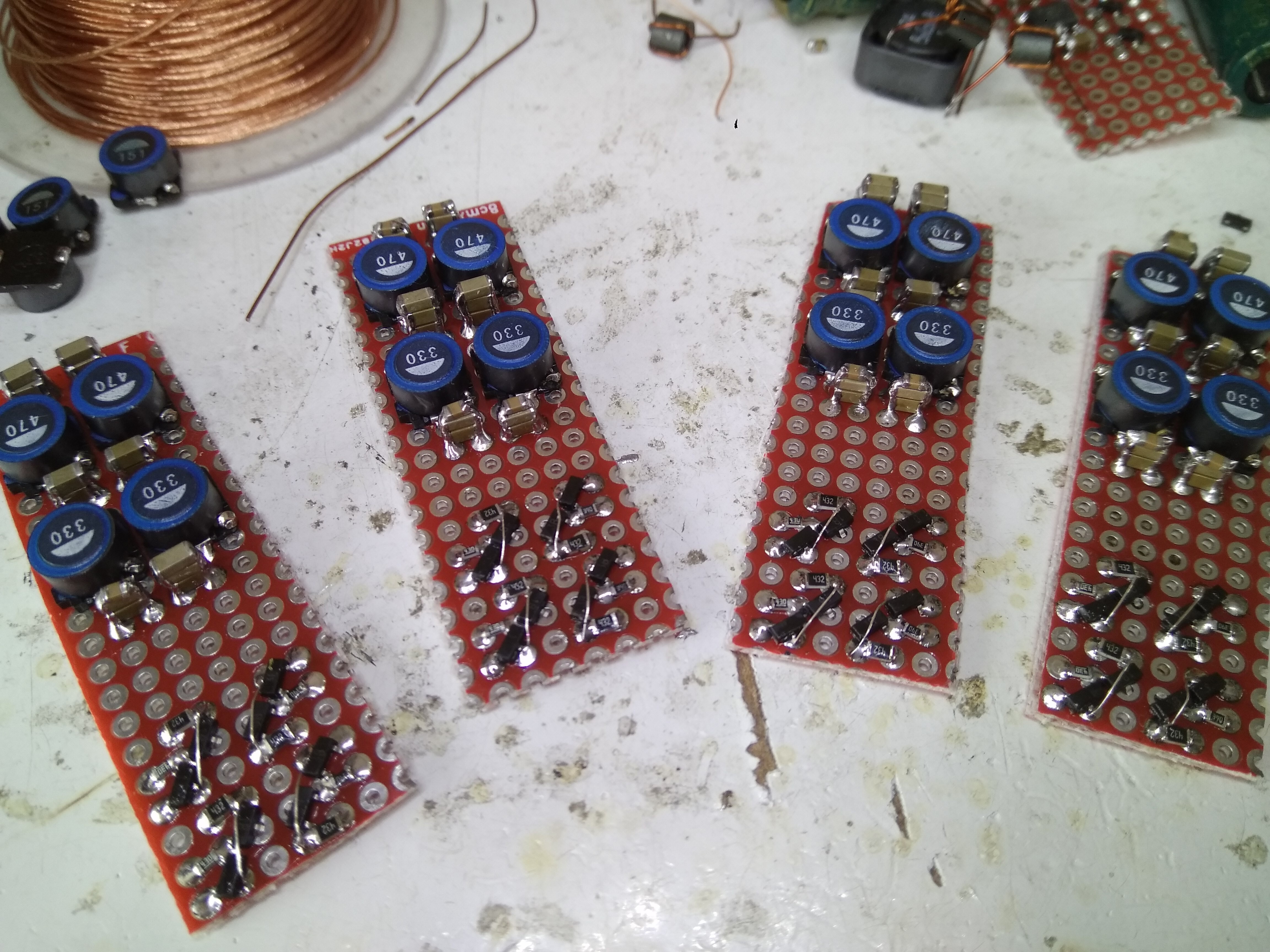
Here's the part-populated filter board. The inductors go to the right, the transistors (current sources and common-base I/V) are to the left.
![]()
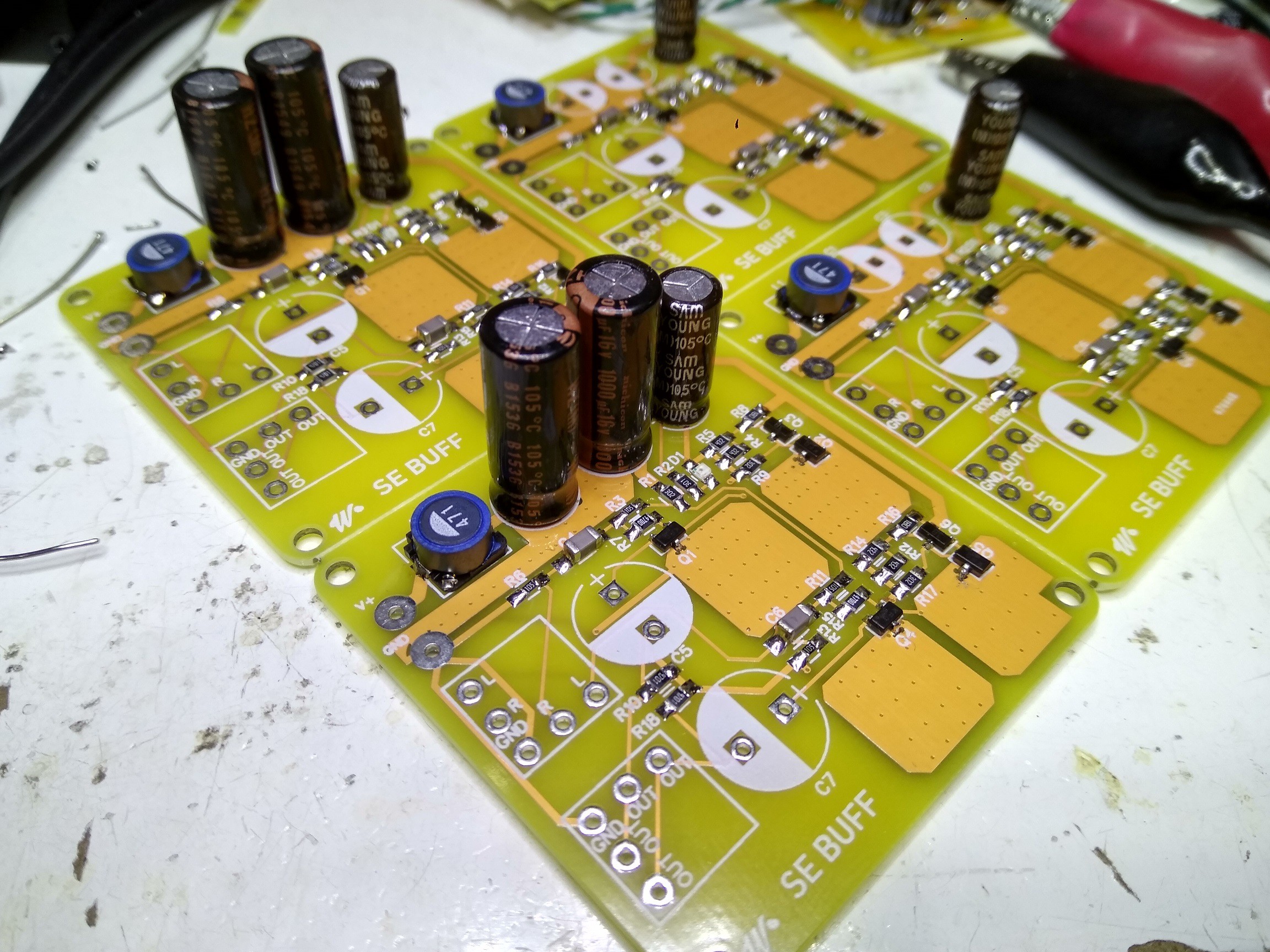
This is a single-ended classA buffer. The copper areas allow the SOT23 transistors to dissipate a bit more heat than normal. While its designed to drive headphones I'm re-purposing it for 0DAC to be a line-level buffer.
-
How to give my listening impressions?
11/30/2017 at 04:14 • 2 commentsI figured in order to have something to say about how this DAC sounds, I'd need a reference to compare it to. So I ordered up some DACs from Taobao which had popular DAC chips inside them and gave them a spin. I reckon the most popular entry-level DAC chips nowadays are the ES9023 and the PCM5102, so I acquired an example of each. As these DACs from Taobao aren't exactly engineered to give any kind of audiophile sound (they're cheap, under 100rmb for PCB only) I played around with the implementations, mostly with power supplies (as these make a large difference, subjectively). I wanted each chip to give of its best - my key weapons in the fight against power supply noise (both input noise and self-noise) are Nichicon HZ capacitors (for lowest ESR) and TDK 7mm inductors (highest Q for the buck).
Upgrading the analog supplies to both ES9023 and PCM5102 makes an improvement but does not bring either of these two DACs into the same league subjectively as lingDAC. The differences are primarily noticeable in dynamics - in comparison to lingDAC both these single chip DACs add noise to the sound, the ES9023 being the worse offender of the two . Now the noise I'm hearing isn't the noise in the absence of signal, these DACs have excellent SNRs so subjectively are dead quiet with no music playing. Rather its noise modulated by the signal that I'm hearing, and this is only really noticeable in comparison with a DAC which doesn't have it. Otherwise my attention isn't drawn to it - I've listened to digitally recorded music for decades and only recently realized what I'd been missing all that time.
When I talk of 'dynamics' I mean the audio equivalent of contrast ratio for displays - a DAC with great dynamics delivers blacker blacks and more startling 'whites'. Blacker blacks is subjectively perceived as 'interest factor' - the DAC encourages me to 'listen in' somehow, I find I'm curious about what I'm listening to even if its something familiar. Whiter whites is perceived as 'jump factor' - the ability to trigger my startle reflex. Of course these aspects depend on the recording to some degree, not all recordings are equal in perceived dynamics. Older analog recordings often do a better job with preserving the contrast ratio of the original performance. As I'm a fan of classical, Decca analog recordings are real stand-outs and in my experience hard to beat for dynamics. Their newer digital originated (DDD) stuff somehow doesn't quite measure up,
Here's an example of some of the best of Decca's analog - https://www.amazon.com/Romantic-Russia-Borodin-Mussorgsky-Tchaikovsky/dp/B000V9CJFE/ref=sr_1_2?ie=UTF8&qid=1512014543&sr=8-2
You'll note more than one reviewer here remarks on the drive and energy of the later recordings (not the Tchaik) - if some of this doesn't make your spine tingle, you've not yet gotten the right DAC for the job.
Here's another example with superb dynamics - even though compression artifacts are obvious on the 30s samples at such low bit rates this is still stirring stuff - https://www.amazon.com/Falla-Three-Cornered-Hat-Ansermet-Berganza/dp/B00004TEUY/ref=sr_1_1?s=music&ie=UTF8&qid=1512093335&sr=1-1
-
Beta prototype assembled
11/15/2017 at 05:14 • 0 comments![]()
Listening report to follow....
-
Filter I/V boards
11/06/2017 at 08:47 • 0 commentsBuilding up the filters takes time due to the painstaking process of ensuring the reactive components (inductors and capacitors) are close enough in tolerance to get to within spitting distance of the target filter response.
Inductors I measure to 1uH and bin them. The mode for the two values seems so far (with about 40 measured of each to date) 30uH and 43uH, slightly under 10% below the nominal values. Capacitors I trim by adding in paralleled units after measuring them. After soldering its essential to allow enough time for cooling and relaxation of thermal stresses before measuring
![]()
- I allow 10mins minimum for this, but if I see the capacitance still decreasing I'll allow more time. What I call the 'tuning networks' (RC in parallel with inductors) are soldered under the board, using 0805 and 0603s. The main shunt capacitors are generally 1206 and visible in stacks in the above shot. Occasionally the 1206s I'll trim with an 0805 on top, aiming to get within 2% of the value on the schematic.
At the front of the boards in the picture are the current sources used to bias the I/V transistors (not yet fitted in this pic).
-
Upgrading USB power
10/16/2017 at 14:37 • 0 commentsI tried quite hard to get this DAC operating on the 'native' USB power from my PC, but it proved not possible to attenuate the low frequency noise on the supply sufficiently. So I've gone for a step up voltage converter to boost the 5V rail to nearly 10V and then regulate it down again.
![]()
An LM2662 performs the step-up task admirably - chosen because its a switched capacitor kind of boost converter, rather than the more normal inductive boost circuit. Inductors tend to be rather leaky and I didn't want to radiate any ultrasonic magnetic field in the tight confines of this DAC's enclosure. Particularly as I have 4 inductors in the anti-imaging filter which are likely to pick up magnetic radiation to some degree.
The other bits on the board are a TL431 (6.6V) and two NPN pass transistors to provide supplies to the DAC array and I/V.
-
Working on a DAC demonstrator
10/06/2017 at 00:58 • 0 commentsSince the lingDAC has only I2S input I need a quick and dirty way to provide the rest of the infrastructure to get something to listen to. Taobao comes to the rescue as on there are a few DACs based on TDA1387 which have digital front-ends on them and enough room inside to hide a filter/IV board. Here is the cheapest one : 4 * TDA1387 USB DAC. I have bought my first two of these with cases but the seller also sells just the PCB as a kit. My gf persuaded him to solder on the CM108 as that's a little tricky to do by hand, so we have more on order at the princely sum of 44rmb for just the PCB and kit of parts.
Firstly its necessary to make some modifications to the board to accept the lingDAC filter/IV stage. Here's a picture of the mods beginning -
![]()
The parts just to the north of the RCA outs are passive IV/filter components which the lingDAC PCB will replace. So they must come out - here I've pulled out caps (2n2 and 220p) and the output coupling caps (CR, CL) which were electrolytics. The 1ks are the I/V resistors, we need to change those to 680ohm.
The next set of mods are to the power supply as the stock board has inadequate filtering on the 5V USB rail.
Audiophile-sounding DAC for almost no money
0DAC - delivers engaging, immersive sound with a pricetag at least two orders of magnitude from commercial audiophile DACs