Dan Schneider
-
Future Hardware Research
10/19/2017 at 23:41 • 0 commentsSince building our hardware prototype, a great deal of our research has centered around how we can improve the real-life performance of the SNAP concept. The single greatest limitation of our current prototype is probably the amount of noise and incorrectly measured points in the depth map. Following this, the limited field of view of the depth camera is our second greatest limitation. We've considered a couple of different options to improve on these limitations: a newer depth camera, and Stereo Visual Odometry.
Intel's New Depth Cameras
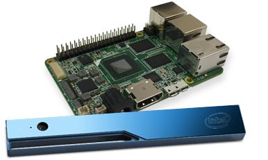
We recently received an email from Intel informing us that the RealSense Robotic Development Kit is being phased out and sold at a discounted price in anticipation of the release of their newest RealSense units. We promptly bought another RealSense RDK and began to research the new depth camera offerings. They look like they could be decent platform, with a few potential issues. Shown below is the Intel RealSense D435.
![]()
The listed FOV is 91.2 degrees horizontal by 65.5 degrees vertical, which is almost twice the FOV of the R200 that we are currently using. In addition, the depth output is now up to 1280*720 @ 90FPS, increased from 640*480 @ 30FPS. However, this model is pricier than the old one, with the camera alone costing $180 and no development kits listed yet. This could be a very promising offering for SNAP version 2 if the image quality is high and development kits are available.
Stereo Visual Odometry
Another completely different option we've considered is rolling our own stereo visual odometry solution. In SVO, two cameras facing the same direction are used to compute a depth map by finding matching points in the two images and computing the depth using the offset between the points, similarly to how the human eyes gauge distance. The image shown below demonstrates the matching of features between the two images. Source: http://www.mtbs3d.com/phpBB/viewtopic.php?f=138&t=18055
![]()
This imaging technique could allow us to use wide angle lenses, or even multiple cameras to provide a very wide field of view. However, it also requires a lot more computational power than a bundled depth camera solution and it is dependent on visible light for reliable output.
With either of these imaging solutions, an ideal application would be to create a real-time SLAM (simultaneous locating and mapping) algorithm that allows SNAP to remember rooms, objects, and places and to use this data to provide clear and timely cues to the wearer about their surroundings. This is a very computationally difficult problem, but it's never to early to make design decisions with this potential in mind. It's clear that SNAP only stands to benefit from the increasing level of corporate and public interest in computer vision and depth cameras.
-
Building the Hardware Prototype
09/03/2017 at 18:31 • 0 commentsWe intended to start development with a simulator and audio generation software running on a PC, so that different depth-to-sound configurations could be tested. However, development moved very quickly on the simulation, and things got out of hand. Once we had a running simulation the natural next step seemed to be to take things to hardware.
The Dev Kit
There are a number of different depth camera platforms out there with varying levels of documentation, priciness, functionality, and portability. The one that most people have heard of is the XBOX Kinect. However, the platform that really caught our eye was Intel's RealSense cameras. Designed for use on portable platforms such as tablets and laptops, these cameras have an appealingly small form factor and power consumption. Our solution of choice, the Intel RealSense Robotic Development Kit was a $250 package that includes a RealSense R200 camera and AAEON Up Board with a quad-core Intel Atom processor and quite a few different IOs.
![]()
The Up board also takes a 5V input, making it easy to power with a common 5V USB power bank for portable operation.
Setting up the board
The first thing we did was install Ubuntu on the Up board using a tutorial from Intel. While our back end software was written for windows, OpenCV and OpenAL are both available on Linux so we hoped it wouldn't be too hard to adapt it for Ubuntu. It's technically possible to run Windows on the Up board, but we weren't sure how we'd work out the drivers for the RealSense camera.
The next step was to install Eclipse, the free open source IDE that we used to adapt our back end software to our Up board.
Adapting the Back End
Our back end software was designed to read a depth image from the system RAM and perform audio conversion on that. However, we had to get a depth stream directly from the camera into OpenCV for our hardware prototype. This turned out to not be too hard after all, using this tutorial:
https://software.intel.com/en-us/articles/using-librealsense-and-opencv-to-stream-rgb-and-depth-data
This results in an updated depth Mat for every frame received from the camera, just like we had in the original back end. Because of this, our back end software didn't require much adaptation at all! The tutorial even shows how to set up an Eclipse project with all the correct dependencies to use OpenCV.
Powering the board
As noted before, the Up board takes a 5V input. However, it can draw up to 4A of input current, which is far more than any USB power bank could provide that we could find. So, we just cheated and bought a cheap 16750mah USB power bank with two 2A outputs, and put the 5V and ground lines from those outputs in parallel on a custom wire harness to give us 4A of maximum total output. This has been working fine so far.
![]()
Using the Prototype
While we knew that there would be discrepancies between the depth data received in the simulation and the depth data from our real-life camera, it was surprising how many different factors changed. One of the most noticeable was that the RealSense's angular field of vision was fairly limited, whereas the camera field of vision is completely adjustable in Unity. This gave us good angular resolution with the RealSense, but a lot of head movement was required to take in your surroundings.
In addition, the RealSense also struggles to pick up reflective and transparent surfaces. We haven't tested it anywhere were there are a lot of glass doors, but in the future we may choose to augment the depth camera with something like an ultrasound sensor to ensure that users don't walk into windows.
-
Hardware Demo 1
09/03/2017 at 16:41 • 0 commentsDemonstrating some basic functionality of the hardware prototype. I am not well practiced at using the system yet, and we have yet to optimize the feedback, but the binaural feedback is so natural it can already be used.
Morgan and I can also play a sort of "hide and seek" where she tries to sneak by me, but we will need another person to film it. After this demo, Morgan donned the headset and had a go at finding me in the room with much success.
On a more technical note, the experiment setting here is important. We are located indoors, meaning there are walls and several pieces of furniture surrounding me. These objects come through as sound sources, and it is important that we are able to distinguish them from one another. Identifying Morgan's hand may seem trivial, but it is significant that I am able to detect her hand apart from the nearby wall.
This first generation software is producing audio feedback which fades Left-Right-Left. This meant that I had to wait for the feedback to sweep back and forth before I could tell which hand Morgan was raising. The inherent delay was somewhat disorienting, and resulted in my slow reaction times, but nevertheless I was able to successfully identify the correct hand each time she raised it.
We will be adjusting the feedback to sweep from center outward, and again to remove the sweep altogether and give the user a full field of sound all at once.
While we definitely have more work to do in developing better feedback parameters, these simple experiments make it clear that the idea is completely feasible and we are on the right track.
-
Depth To Audio: Where the Magic Happens
09/03/2017 at 00:59 • 0 commentsIt was decided early on in the project that our "back end" software would be coded separately and run in a separate process from the simulator. This was done so that in the future, the "back end" code would be easier to port from working with depth data from a simulator, to depth data from a hardware prototype.
![]()
The back end has three main processing steps:
- Read depth data as an image
- Use computer vision to process the image
- Turn the data from the image into sound
We first had to choose how to get our depth data from the simulator (DLL, shader, and C# script) into the back end, reliably and with little lag. Our solution came in the form of shared mapped memory, available in both Windows and Unix. Shared mapped memory is simply a block in your PC's RAM that can be accessed and written to and read from by multiple processes. This block can be found and accessed using a unique identifier that is set by the software that creates it. In our case, the DLL Unity plugin creates the memory space and our back end software opens it.
Software Packages
Our 3D depth data is output from Unity as a simple bitmap image, just like an uncompressed digital photo. However, instead of color, each pixel represents how far the next object is from the camera. Because of this similarity to regular images, we chose to use the popular computer vision library OpenCV to do our image processing. To generate audio, we used the open-source spatial audio library OpenAL.
Methodology
There seemed to be two different ways to go about getting converting our 3D depth data to audio: a smart way and a dumb way. The smart way would try to use advanced computer vision techniques such as edge detection, plane detection, object detection, and facial recognition to process the depth data in real time and attempt to decide what was important to the user, and then use different audio signals to describe different types of objects and landscapes around them. The dumb way was to perform no advanced computer vision, and instead use the most direct possible mapping of 3D space to sound and rely on the brain's inherent ability to restructure itself and figure out new ways to use the senses.
Computer Vision
Pros: Potentially provides more detail and pertinent information to the user
Cons: Could be dangerous if it gets confused, hard to make reliable and effective, computationally intensive
Simple Depth-To-Audio
Pros: Less computationally intensive, makes the brain do the heavy lifting, potentially faster response and lag time
Cons: Possibly lower signal-to-noise ratio and less perceptible detail
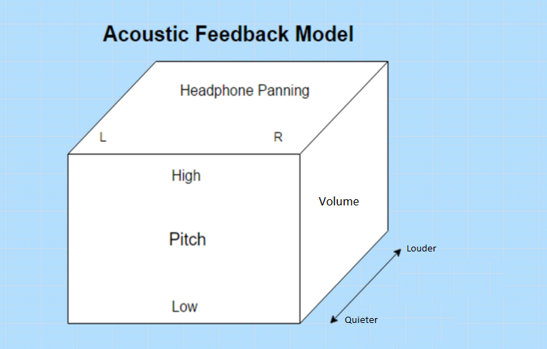
The smart way sounds pretty sexy and much more high-tech, but none of us had a background in advanced computer vision and the dumb way had it's own upsides. For example, a recent Wired article discusses how a blind woman can perceive her surroundings in incredible detail using an amazing program called the vOICe, using simply a low-resolution black and white webcam. Her brain was able to retrain itself to interpret audio as visual data with fantastic success. The vOICe has a very simple algorithm, in which distance corresponds to volume and pitch corresponds to vertical position.
![]()
We were inspired by this amazing success with such a simple algorithm. Before seeing this article, we had tried a few similar algorithms with limited success. We attempted to divide the depth data into a number of rectangular regions and pulse sound at a rate corresponding to the average distance of each region. However, having sound output simultaneously from every angle of depth data quickly became an unintelligible mess, even with very low resolutions. The trick used in the vOICe, and the latest version of our audio generation software, is to pan the audio from left-to-right at a user configurable rate. That way, the user will hear sounds from one horizontal angle at a time, rather than the whole depth image simultaneously.
Below is a pseudo-code block to demonstrate the algorithm.
Sounds[4] = SoundSources
Regions[4][4] = GetRegions(DepthData)
#X is horizontal position in depth data and in spatial sound position (L-R panning)
#Y is vertical position in depth data and pitch of sound
while(1):
    for x in range(0, 4):
        StopSounds(Sounds)
        for y in range(0, 4):
            Sounds[y].Volume = Regions[x][y].AverageDepth
            Sounds[y].Pitch = Coefficient * y
            Sounds[y].HorizontalPosition = x
        PlaySounds(Sounds)
        Sleep(0.25 seconds)
Obviously we had far more than 4 horizontal and vertical points, and the real code is in C++ (attached in the file list) so it's a lot more confusing. We also added another program that opens a GUI that allows the user to adjust several parameters, such as the rate of left-to-right looping, the maximum and minimum pitch, the number of horizontal steps, and more.
-
Simulator Design
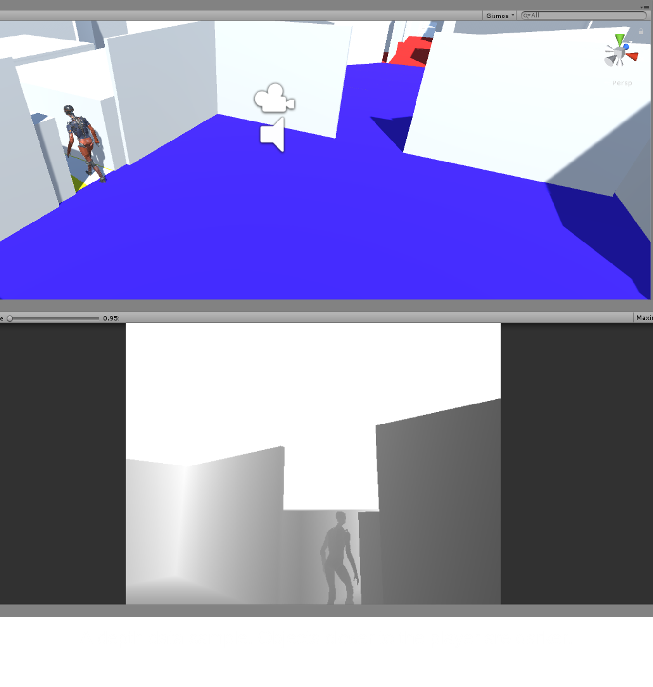
09/03/2017 at 00:09 • 0 comments![]()
For our simulator, we sought out a 3D game engine that was highly customizable, easy to use, easy to ship to users, and would provide easy access to depth data that would let us simulate the output from the real-life depth camera. We settled on Unity, a free, highly popular game design suite and 3D engine. Unity can be used to produce games for Android, iOS, Mac, and PC, and makes it very easy to get up and running with a FPS-style game, which is what we wanted our simulator to be. Our simulator currently only works on Windows, but we may port it to other platforms as the need and possibility arises.
As it turned out, getting the depth data from Unity was not as easy as we thought it might be, and may have been to most hack-ish part of the whole project. Unity is closed source, and it can be very hard to tell what is going on behind the scenes in the 3D engine in graphics card. After months of attempting to directly find and extract the depth buffer so that our back-end sound generation software could access it, we eventually settled upon the following, somewhat round-about method.
Shader: DepthToColorShader.shader
For the first step of extracting the depth buffer, we used a custom shader script that runs on the GPU to read pixels from the depth buffer and convert them to a grayscale image.
The shader was essentially copied from this extremely useful tutorial:
http://williamchyr.com/2013/11/unity-shaders-depth-and-normal-textures/
It also provides a great primer on shaders and graphics C# scripts in Unity.
Graphics C# Script: DepthCopyScript.cs
For the next step in the image pipeline, we wrote a graphics script for Unity that would read the grayscale image generated by the shader and copy it to a byte array in RAM. The basic shader operation of this script was based off of the C# example of the tutorial above, and simply applies the shader to the in-game camera using the line below in the function OnRenderImage():
void OnRenderImage(RenderTexture source, RenderTexture destination)
    {
    Graphics.Blit(source, destination, mat);
Then, things get a little more complicated. The Unity ReadPixels() function is used to read the pixels from the currently active material (the one we applied the shader to) into a byte array, as shown below.
RenderTexture.active = destination;
        //Reads the currently active rendertexture to the texture2d
        tex.ReadPixels(new Rect(0, 0, GetComponent<Camera>().pixelWidth, GetComponent<Camera>().pixelHeight), 0, 0, false);
        tex.Apply();
        bytes = tex.GetRawTextureData();
Then, the DLL comes in.
Unity DLL Plugin: RenderingPlugin.cpp
C# scripts in Unity are pretty locked down and can't use any fun low-level things like shared memory, or pointers except in a very limited capacity. However, Unity provides a handy Windows DLL interface that lets you interface to your own C++ or C program that you put in a DLL. They also luckily provide a plugin example that we based our DLL plugin off of after fruitlessly attempting to create a DLL plugin from scratch.
The original DLL plugin uses OpenGL to do fancy graphics stuff and draw on the screen. However, we just wanted something that could take our byte array of depth pixels from the C# script and put it in a named shared memory space that our depth-to-audio software could access.
The C# script calls our SetupReadPixels function in the DLL to get a pointer to the name shared memory space like this:
unmanagedPointer = SetupReadPixels (xSize, ySize);and then, every frame this function is called once the byte array has been filled with pixels:
Marshal.Copy (bytes, 0, unmanagedPointer, bytes.Length);
Once this is all done, at the end of OnRenderImage(), the C# script uses the following line to put a different Unity material on the screen (we just used a blank material so the end user wouldn't be able to see the depth map and cheat).
Graphics.Blit(source, destination, BlankMat);See the uploaded code to see our shader, DLL plugin, and C# script! In my next log, I will cover our depth-to-audio software and how the shared memory works.
-
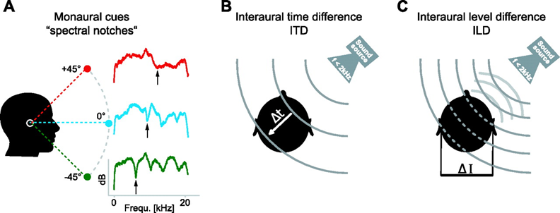
Binaural Hearing and Sound Localization
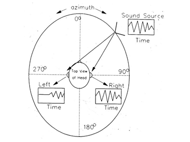
09/02/2017 at 22:03 • 0 commentsMost animals accomplish localization of sounds using Interaural Time Differencing (ITD) and Interaural Level Differencing (ILD). Imagine the sound source in the image below is a balloon popping somewhere out in front of you. The sound from that pop does not travel instantly, so it takes some time for it to wrap around your head. This means that, unless a sound is directly in front of you, the sound will enter one ear before the other.
- ITD: This is the amount of time that passes between when the first ear hears the pop, and when the other ear hears it. Sound moves at about 340 m/s, meaning the ITD will range from 0.000 (s) when a sound source is straight ahead, and 0.001 (s) when the source is at 90°. Likewise, the sound of the pop will be quieter on the side facing away from the balloon.
- ILD: This is this difference in apparent volume between your ears. Both ITD and ILD are used together to determine the location of a sound in the azimuthal plane to within 3°.
The sagittal plane (the vertical axis in the image above) is a little less straight forward, because there is no change in ITD or ILD as a sound source moves up or down. To determine the location of a sound above or below us, we use slight variations in hearing caused by the varying density of our head when viewed from different angles. Acoustic vibrations are conducted differently through our jaw than they are thorough our head from above, resulting in certain frequencies being accentuated or dampened. Using these so called "monaural cues" we are able to approximate the sagittal origin of a sound to within about 20°.
The image below gives a visual summary of these three localization mechanisms.
-
SNAP Simulator
09/02/2017 at 21:29 • 0 commentsThe success of SNAP depends highly on the intuitive nature of the acoustic feedback. While many aspects of sound localization may be calculated with certainty, user data will be needed to determine the best frequencies, waveforms, and volumes to use. Creating an acoustic overlay of the environment without distracting the user or impeding their ability to hear external sounds will require iterative experimentation and fine adjustments.
We are hence developing a simulator which will allow anyone with a computer and pair of headphones to navigate a virtual environment using our SNAP feedback methods, and provide us with feedback and data. Development for this test bed has been done by students at the University of Idaho through the Capstone Senior Design program. The general project goals are as follows:
- Configurable environment allowing for variation in test courses/maps
- Integrated SNAP acoustic feedback with configuration options
- Downloadable package for ease of distribution
- Functionality portable to wearable hardware
-
Project Concept
09/01/2017 at 02:29 • 0 commentsIn the past few years, depth cameras such as the XBOX Kinect and Intel Realsense have become incredibly cheap and accessible to a huge audience of consumers and makers. Hackers have seized this opportunity and used them to enable an amazing array of projects including 3D scanners, motion trackers, and autonomous robots. However, very few projects have explored the potential of these cameras to augment human perception.
We sought to use a depth camera to assist the visually impaired in navigating and perceiving their environments, and give them a new level of freedom of movement through both familiar and unfamiliar environments. The human brain has an amazing ability to adapt and make up for deficits in sensing by heightening other senses. With this in mind, we asked ourselves: if we can see through our eyes, why not our ears?
Humans also have an impressive ability to localize the vertical and horizontal location and distance of sound while simultaneously distinguishing multiple different sound sources. Vertical and horizontal localization coupled with distance are all that you really need to visually navigate your environment; color and brightness are secondary. If we could take the 3D data from a depth camera and translate it into audio while preserving detail, we could give the visually impaired a tool that would let them fearlessly navigate novel environments without the use of a cane or service animal.
SNAP: Augmented Echolocation
Sightless Navigation And Perception (SNAP) translates surroundings into sound, providing continuous binaural feedback about the environment.