-
Software
09/04/2017 at 04:32 • 0 commentsSoftware Design
The language used for software development was Java®. This programming environment evolves from C and C ++, but it eliminates certain aspects of the latter two and constitutes an object-oriented language.
Java® is a useful language for almost all kinds of problems, its download is free. Among its features are:
• "Client" applications are those that run on a single computer without having to connect to another machine. They can be used for example to perform calculations.
• "Client / server" applications: they are programming that need to be connected to another machine to ask for some service in a more or less continuous way, such as the use of a database.
• Web applications: Java programs that run on a web server. These applications receive applications from a computer and send to the browser (Firefox, Google Chrome, etc.) that acts as their client. (Rodríguez, 2016)
This computer platform was selected over other languages, for three reasons:
• It is multiplatform, ie with Java® you can do the same application written once and that works on any operating system: Linux, Windows, Mac, among others.
• It is free, you do not need to buy a license of any kind.
• Flexibility, when updating an application is not necessary to rewrite it, Java allows to use the same code and add new features without altering the initial one (Monillo007, 2016).Interface
The software developed has a user-friendly interface, and an update of the received data automatically. For the same it is necessary to have installed the Google Drive® application, which will allow access to the files of the data obtained in the patient's cell phone from the health professional's computer.
The reason we selected the data to be uploaded to Google Drive® plataform is that the Android operating system that owns the cell phone was developed by Google® as well. This means that all phones have the application of Drive, which allows to synchronize the files of the phone with the readings made so they can be uploaded to the device of the health professional.
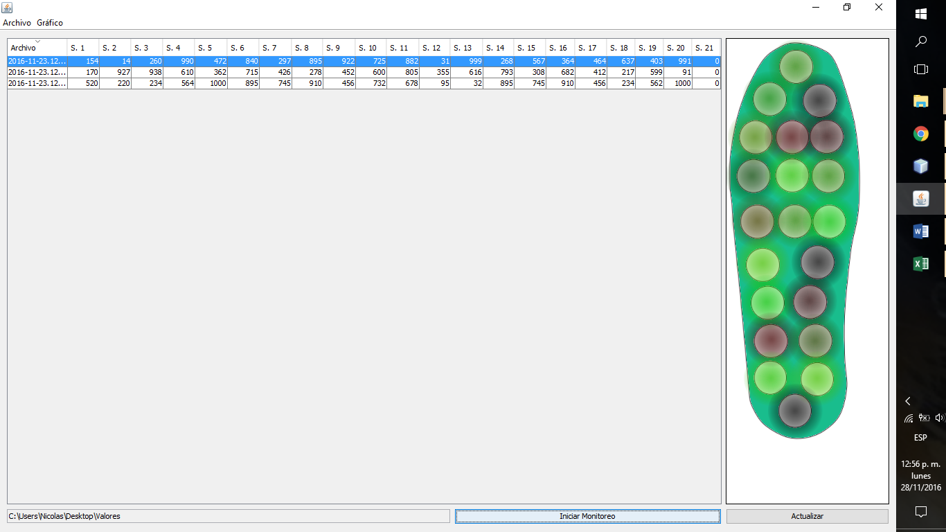
As shown in Figure 158: Software interface PCIlustration 158, on the left is a table where the first co-lumina indicates the date and time of the measurement performed, while the rest are for the values of the readings made in each of the 21 sensors that own the template.
To the right of the image, there is a drawing with the geometry of the template and inside it, circles that correspond to the location of each of the sensors.
On the lower left margin, is indicated from which folder is acquired the file with the readings obtained and to its right there are two buttons, one to update the files of the source folder and another to start the monitoring.![]()
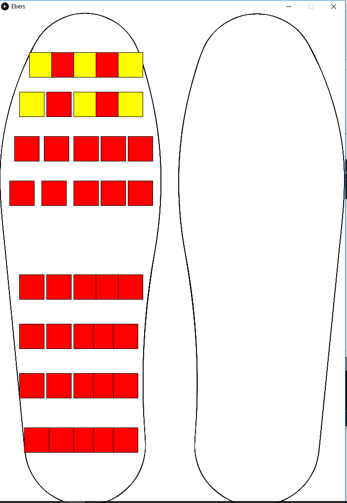
Another option we have is to transmit data direct to the PC via Bluetooth. In this case we use a processing code that works similar to the java soft.
![]()
-
Interface board
09/04/2017 at 04:13 • 0 commentsAs the name says this stage has the objective of functioning as a link between two different levels. The first is the flexible circuit developed with silver ink (the active zone of the sensors), and the second is to connect all the electronics in a reduced and efficient way.
![]()
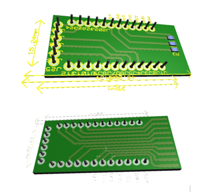
It consists of a double face plate, type FR4 (fiberglass), which improves electromagnetic interference and allows it to have a longer duration over time. So that tracks that do not work as contacts are not exposed (reacting with oxygen, with its consequent oxidation), were coated with flux that also works as an insulator of the tracks and facilitates their welding.
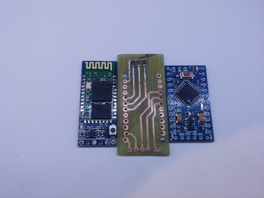
In addition to this, the lower surface has 3 resistances of 15KOhm which are parts of the resistive divider needed by the sensors. These are SMD type because they take up less space, consume less energy and do not need to drill the plate.![]()
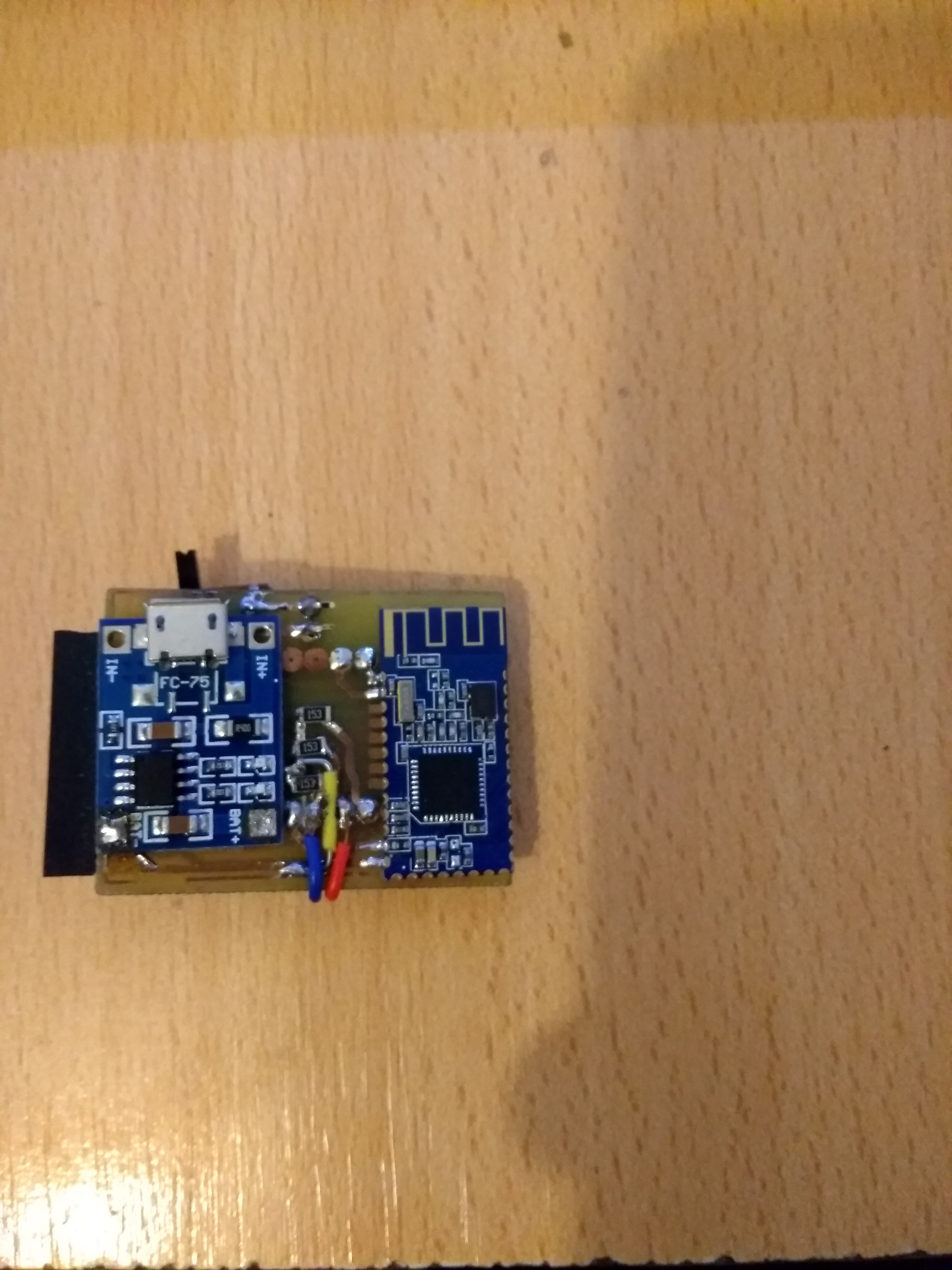
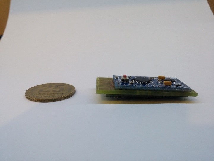
![]() The second version incorporate a tp4056 for lipo battery and HM-10 Ble module
The second version incorporate a tp4056 for lipo battery and HM-10 Ble module ![]()
![]()
-
Send data
09/04/2017 at 03:59 • 0 commentsFor reading and sending data will require two components: an Arduino board with a microcontroller that performs the first and a Bluetooth module that allows sending the measurements made, wirelessly, to the cell phone. In turn, you need to be able to connect the template with this electronics. Here it presents a difficulty since you can not sol-give the silver tracks. To solve this issue, contacts were made which are to be fixed by pressure between the two surfaces.
As mentioned above, 7 digital outputs and 3 analog inputs are used for data readings. Once the data of each sensor are obtained, they are stored on the Arduino board and then sent to a cell phone, which has an application that will be responsible at the end of the day to transfer the readings obtained in a full day to a platform of storage so that the health professional can access the state of the patient's foot. However, in situations of foot pressure, the application offers an alert system that instantly notifies the patient to corroborate the position in which he is or to make a control inside his footwear to confirm that there is not any object that can lead to an injury.
Arduino is an "Open Source" electronic platform based on an easy-to-use hardware and software method so that anyone can do interactive projects. This platform consists of a board that contains a microcontroller with input and output pins that can control motors, actuators, lights and obtain sensor readings. In order to send you orders and perform various actions, you can use a programming environment of the brand known as "Arduino IDE".
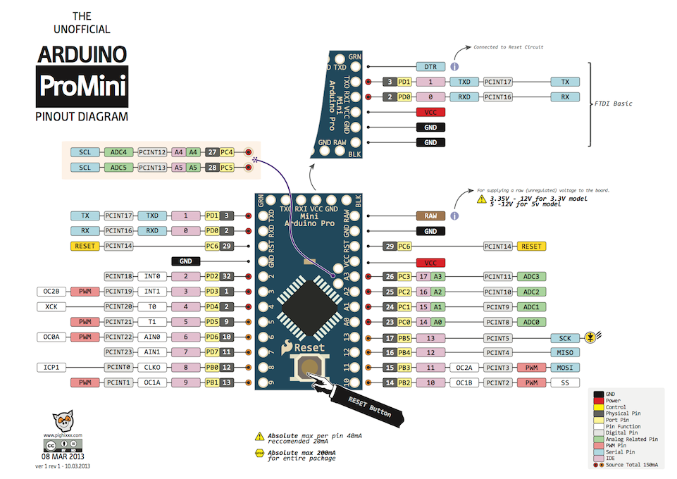
There are several models of these plates, depending on the need and utility can be taken into account various factors such as size, quantity of inputs / outputs, microcontroller used, memory required, consumption, among other aspects that can be taken into account at the time to choose one. In this project due to consumption issues, number of inputs / outputs and mainly size was chosen by the name model Pro Mini.
![]()
Arduino ProMini
Arduino Pro Mini is a board with the ATME-GA328 microcontroller. It has 14 digital pins that can function as inputs and outputs (6 of which can be used as PWM outputs), 6 analog inputs, a reset button and pin mounting holes. Six pins can be connected to an FTDI-type cable or to a Sparkfun board to provide power and USB communication to the Arduino. It has a circuit that operates with 3.3 V and 8 MHz and at 5 V with 16 MHz (Arduino, 2016).The reasons for selecting the Arduino platform for the project were:
• Easy to program: in an Arduino-based development environment (IDE), it has pre-set functions that reduce the logic and reading of inputs, control of times and outputs in a semantic and intuitive way. It has the advantage of not needing a type of programming card like other microcontrollers, but the board can be connected to the computer via USB and can load the programs without risk of damaging the card due to its additional protection. The code is extremely friendly and has its own high level language called Processing, although this does not limit Arduino to be programmed in any language.
• Wide variety of documentation and tutorials, from the same page of the company, the IDE comes with many examples, as well as countless YouTube tutorials.
• Libraries for practically any ex-suit component that you want to dock, making it unnecessary to have to use the component datasheet permanently. Among the libraries we can find are Wi-Fi, Bluetooth, Ethernet, Servo, among others.
• Variety of plates, as mentioned earlier in this section, there are plenty of plates every need of the developer. Among them we find the MEGA, ONE, NANO, LEONARDO, PRO MINI, etc.
• Extensive ranges of shields or extra plates that fulfill specific functionalities like Ethernet. Wi-Fi, Blue-tooth, Relay control, among others. They can be coupled to the plate in a simple way and thus generate an increase in the available applications. In addition, Ar-duino is compatible with other brands such as Xbee, Key-two, LCD, SparkFun devices, SD-Card to name a few.
• A point that is of great attraction, is the price. It is much smaller than that of Rapsberry Pi and Microchip Microcontrollers.
• A large number of applications for practically everything to be developed, such as in-flight and data reception via Bluetooth, robotics, sensor reading, biomedicine and telemedicineAs mentioned above, sending the measurements obtained is via the Bluetooth module.
Created in 1994, Bluetooth technology was conceived as a wireless alternative to data cables by transferring information using radio transmissions. The name comes from the twentieth-century fighter who helped unite the fractions of what is now Sweden, Norway and Denmark: Harald Blåtand in English is Harold Bluetooth. Similarly to what this warrior did, Bluetooth seeks connectivity and collaboration between disparate products and industries (Bluetooth, 2016).
Among the most popular applications of this technology we find the ability to connect devices efficiently and quickly, in the same way you can connect these devices to a computer, Tablet, Smartphone, sneakers, watches and in any case that are limited only to the user's imagination and its way of doing so requires little functional energy.
This technology was chosen for the sending of data, since, at present, most people have access to a Smartphone and they are always included in Bluetooth, so that they achieve great accessibility.
Among the advantages we can mention
• It is wireless
• When traveling with our notebook or other wireless device we do not have to worry about the connection cables anymore.
• Bluetooth is an inexpensive technology
• It is automated and does not require connection configuration or having to press any button.
• As for the protocols Bluetooth devices are standardized, ie they work well even if they are different models. The compatibility between different models is safe and can be communicated without problems.
• Low interference is another advantage of Bluetooth as these are mostly avoided by using low-power wireless signals and frequency hopping technology.
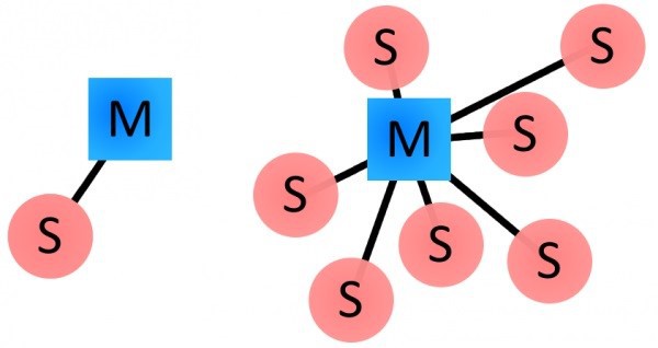
To start talking about Bluetooth devices, it should be clarified that they can act as Masters or Slaves. The difference between one and the other is that the latter can only connect to a Master, on the other hand if they act as Master means that they can connect to several Slaves or allow them to connect and receive information from all of them, handling information transfers (up to a maximum of 7 slaves).
![]()
Difference between Bluetooth devices Teachers and Slaves
Each Bluetooth device has a unique address of 48 bits and a name that serves to identify it more easily to people.
Summarizing the above, a Bluetooth device can be Master or Slave and has a unique address and a name to identify. Sometimes it includes a login PIN or identification number that must be typed in order to gain access to it.
When two Bluetooth devices are linked, a process is started in which they are identified by name, address and, if necessary, the PIN is requested to authorize the connection.
Once this pairing is successfully accomplished, both Bluetooth nodes typically store the other's ID and when they are close, they are again linked without the need for manual intervention.
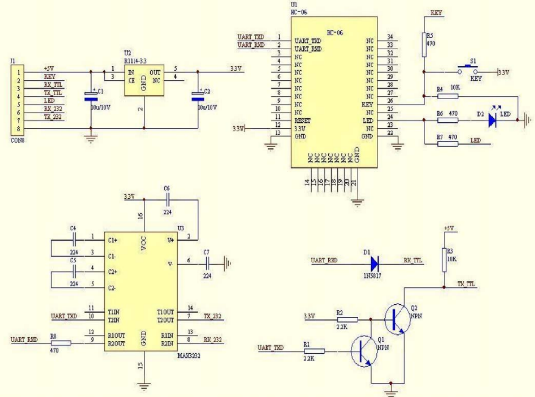
For this type of connections, Bluetooth modules used with the Arduino board have been available for some time. These modules have an adaptation to facilitate their use but with the consequent increase in plate size and energy consumption as it brings integrated circuits to facilitate their connection![]()
-
Fill Patterns
09/04/2017 at 02:31 • 0 commentsAfter designing the template, it was printed. To do this, first determine the solidity, ie, what will be its density of filling. In this way, the piece will be more or less resistant depending on the filling pattern or if solid layers are included therein. If the re-filled density had a value of 100% it would mean that a solid part would be printed, whereas if this value were 0% it would be totally hollow.
![]()
Fill Density Scale
For an increase in the stiffness of the pieces, solid layers are introduced between the filling, ie in addition to the lower and upper solid layers, there will also be more in the intermediate zone. This method will favor robustness, because it allows selecting as many layers of fill as desired. However, it should be noted that the more solid layers you have, the more material you will need and the longer it will take to print.
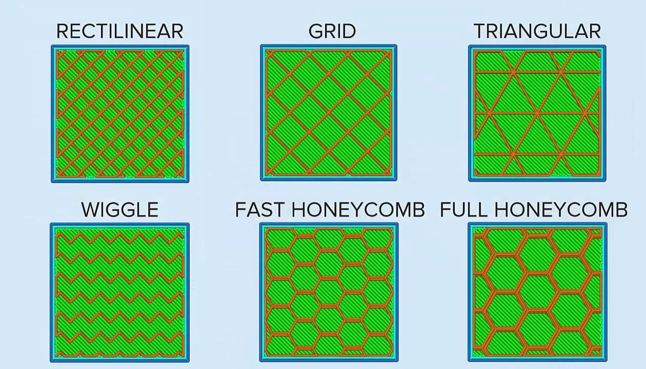
On the other hand, if the fill pattern is used, both the amount of row-ment and the print times would be decreased. For this case, it is recommended to print with fill density ranging between 20% and 60%. Among the different types of patterns we find:
• Rectangular or grid: this is usually the default in the software. It offers a great relation between hardness and speed of printing, although com-stopped with others it takes more time of impression. However, although it fulfills its function, it offers no advantage over the rest.
• Triangular: optimal for parts that need robustness in the walls, as it offers good resistance and high side loads. It is the most time-consuming printing.
• Wiggle or curvilinear: Ideal if you want parts with some flexibility but without losing the robustness.
• Fast HoneyComb or hexagonal: Considered the most optimum for most printed parts. It is the best relationship between used material and resistance making it the most efficient. It im-prime quickly allowing time savings and, as mentioned above, material, while offering a high robustness to the piece and fits most designs.
• Full HoneyComb: similar to the previous one, but its hexagons unlike the previous one have double walls (Experts, 2016).![]()
Filling patterns
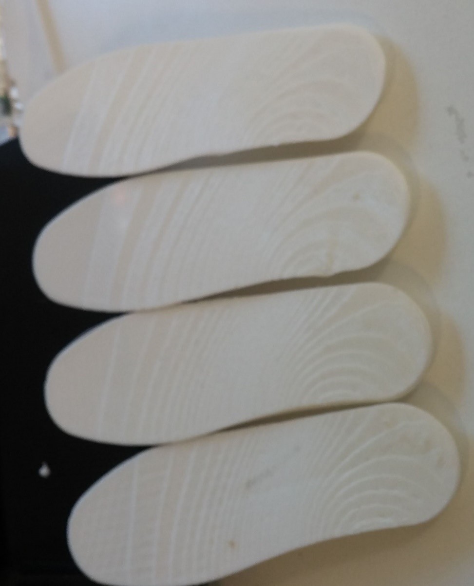
These fill patterns were those used to make the test specimens of scaled templates and thus to be able to determine which has the most appropriate behavior for the project.
![]()
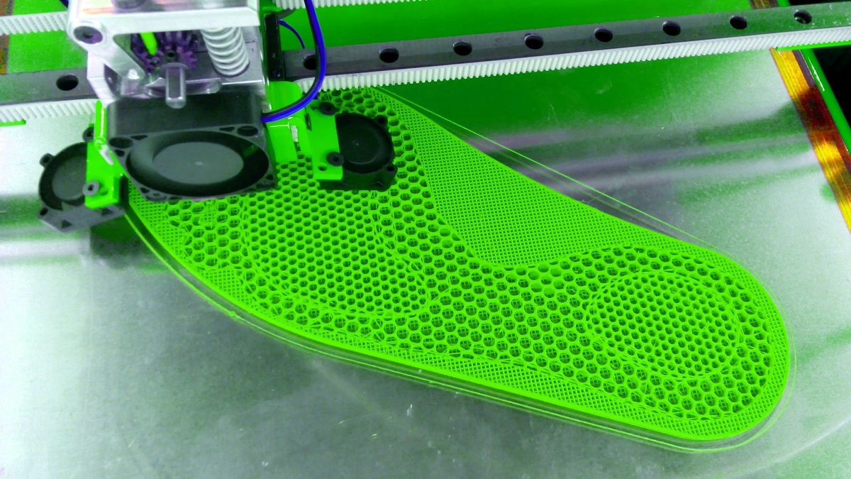
Probes with different filling patternsAfter analyzing, it was decided to use the Wiggle pattern. This is characterized by being the least rigid of all patterns since the frame only has lines in the transverse direction of the piece thus obtaining superior flexibility in the longitudinal direction, which is the axis of greater movement that the template presents. The fill density selected for this template was 20%
![]()
-
3D printed insole
09/04/2017 at 02:25 • 0 commentsSeveral techniques were proposed for the construction of the insole. Some of them consisted of CAD software design, such as AutoCad, Inventor, SolidWorks or some more specific ones like Autodesk Footwear, Delcam Orthotic. These latest ideals for custom design insoles. The disadvantage they have is their high cost and the lack of free licenses for testing or for students which makes it impossible to use them.
Another technique investigated was by means of 3D scanning of a insole of a sports footwear that would be digitized and thus obtaining the mesh of points. With this technique a relatively low resolution was obtained for what was wanted, so it was quickly discarded.
Once the previous options were discarded, the virtual platform of parametric design of insoles "GenSole" (GenSole, 2016) was used. This programming environment has advantages as ease of use as it can enter the necessary parameters, the final model adapts to these measurements. This feature is desirable and important when the user is put in focus, who has particular characteristics in the measurements of his feet.
![]()
GenSole LogoGenSole was developed by "GyRobot", a mechanical design consultancy company located in England. They specialize in the use of CATIA V5, a 3D CAD software product, which can be used to design, simulate and manufacture a wide variety of products. In addition, the company offers 3D printing facilities.
Various facilities are offered by the GenSole website, including:
• The possibility of shaping the top of the insole, from a 3D scan of the user's foot so that it can match the surface and thus generate a more personalized insole.
• Various filling patterns so that the internal mesh of the structure can help discharge high pressures in the sectors where they occur.
• Both the upper and lower surfaces can be printed with perforations to assist in the circulation of air, favoring the breathing of the foot.
• From parametric designs, boundary curves can be edited to fit the user's foot and need (GenSole, 2016).
The options offered by the website were the reason why it was selected to be able to make the surface of the insole in charge of covering the array of sensors that will feel the pressures in the different points of the foot.
On the other hand, with this software you can also generate a rest insole in a more customizable way for your best adaptation and convenience to the person who will use it.
The steps to carry out the insole design, are simple and with a friendly interface, turn the website also offers a video tutorial for the construction of this piece. Once the process is finished, you get an ".STL" extension file that can be opened with other software like Inventor Professional for adding different aspects, editing, among other possibilities. With this file extension, you can perform the slicing that will generate the G-Code, explained above, that will guide the printing in three dimensions.
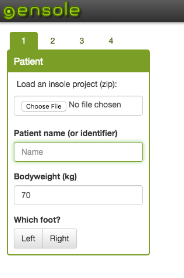
The design of the insole consists of four steps. In the first one, the shoe size is used specifying the size of the shoe used to know the size of the piece. The next parameter is to indicate which foot is the insole (left or right) and is also asked to complete indicating the weight of the user, to be able to determine the density of material that will require the insole to make it as comfortable possible (it is not the same as a plan for an overweight person than for one with an average weight). As an optional service, you can place the name of the user or the one you want, so that it appears written on the piece at the time of printing and give a detail to the piece. In this integrative project as a parameter, a insole size 41 (European scale) was introduced for a person weighing 80 kg, left foot and engraving of Ebers, in honor of the person who discovered the first papyrus where referred to diabetes.
![]()
GenSole user menu
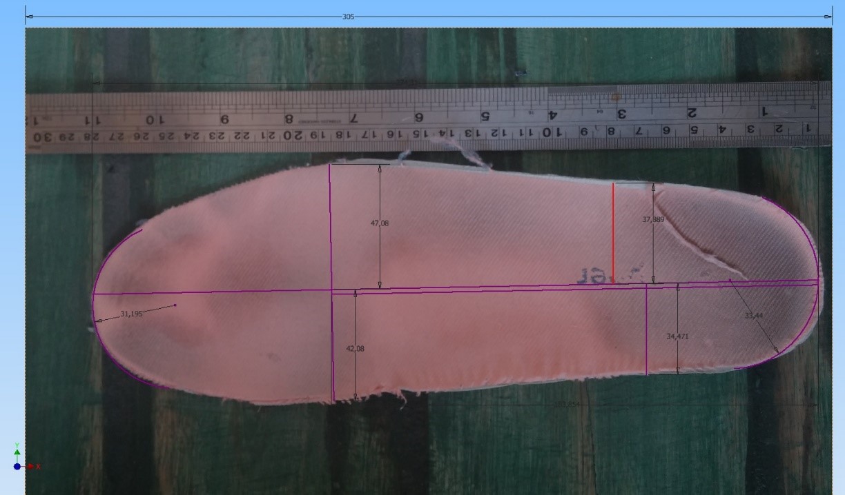
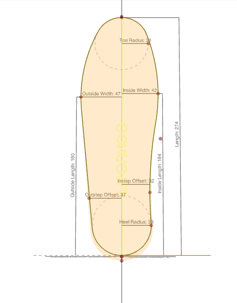
Once this data is entered, proceed to the second step. This consists in entering the parameters of the curvatures. It is recommended from the page to make a photo of a user's plate and on it take the measurements that are needed from the software. Once the image was made, the Autodesk Inventor design software was entered where the required arcs and distances were measured.![]()
![]()
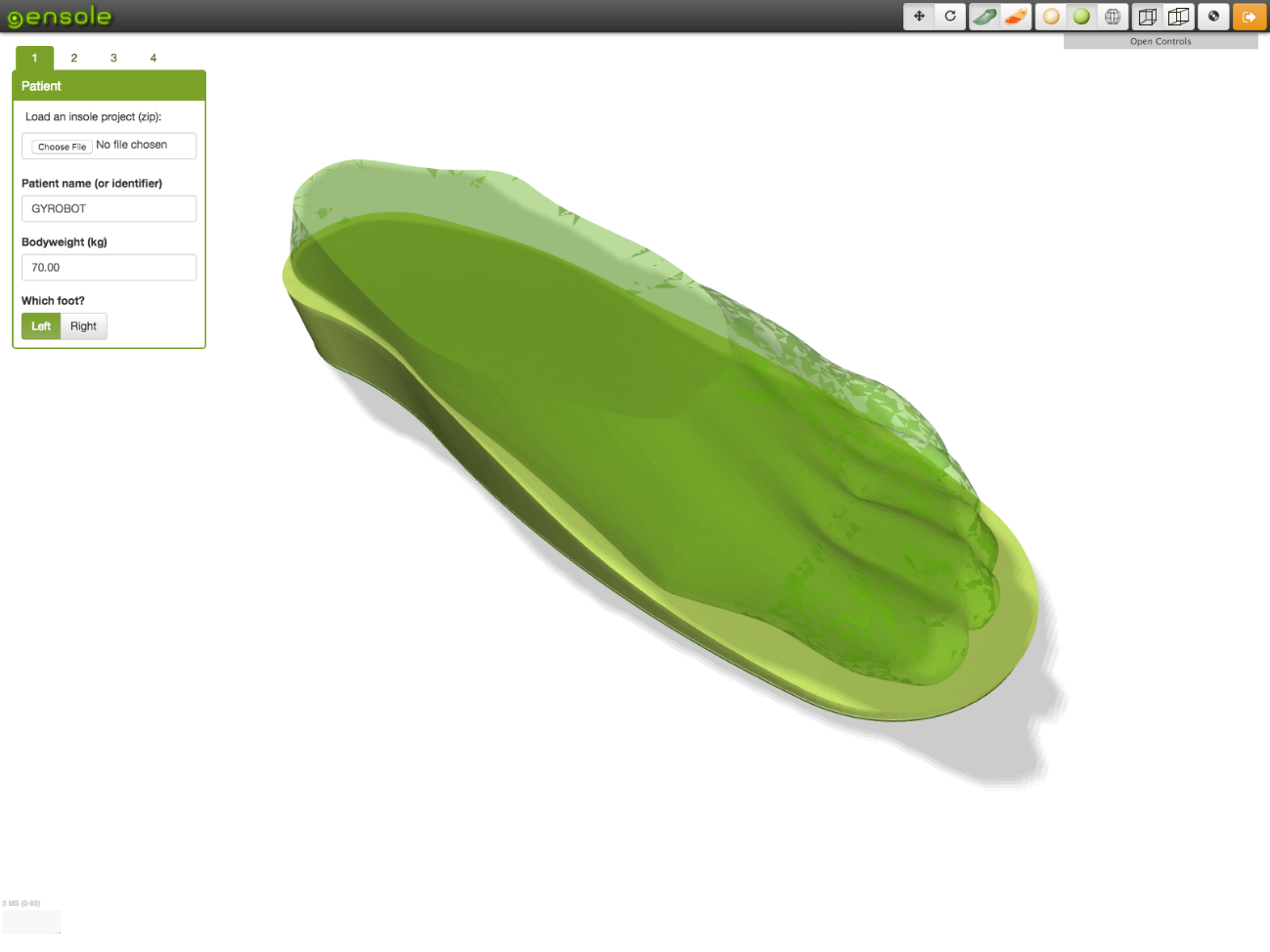
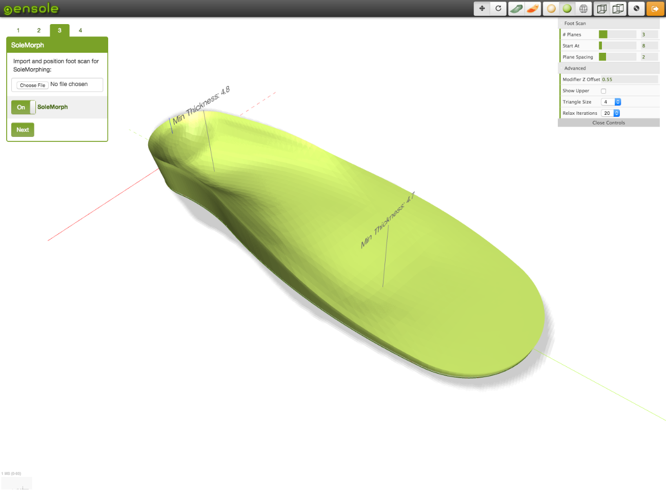
The third stage is very important for custom designs. It allows us to upload three-dimensional models of the user's foot that were previously scanned and digitized. With this technique we obtain a template with the morphological patterns of the patient. As in our work the template was used for diagnosis it was not necessary to perform the scan of the person.
![]()
Software preview where a 3D scan of a foot was imported
![]()
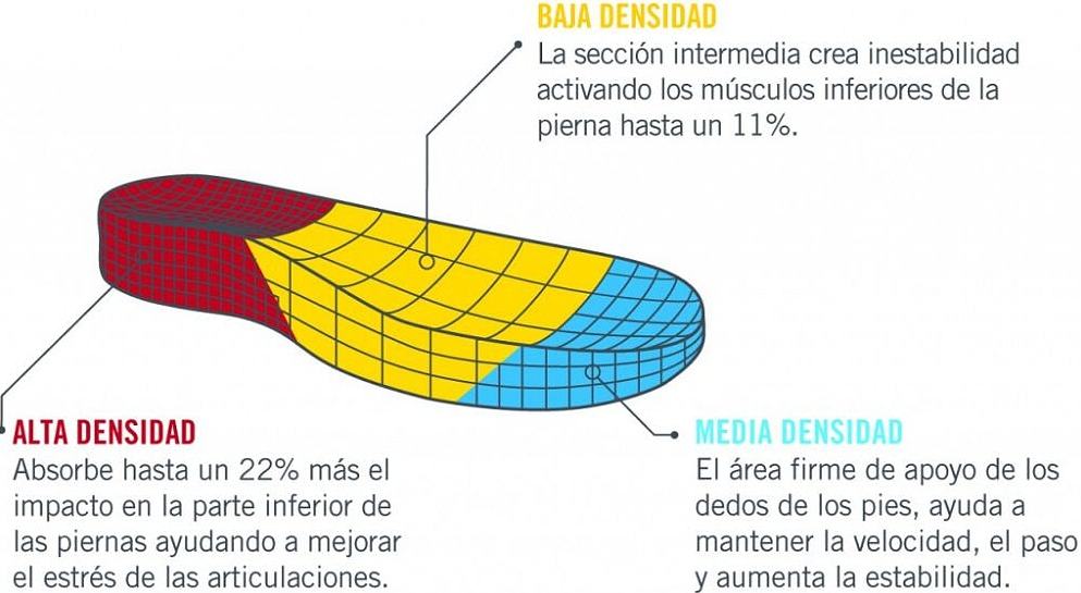
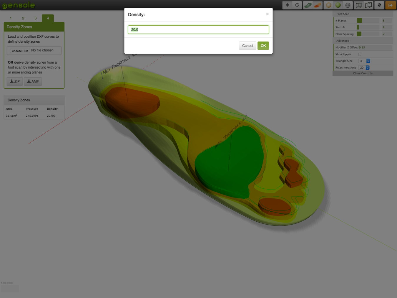
Custom template from a 3D scanThe latter function is perhaps the most important for the treatment of diabetic ulcers. In this stage it is possible to enter the zones of greater load that the patient presents through DXF curves. With this we can change the density of the fill patterns in that area to achieve a more resilient, flexible structure and help to discharge those zones.
![]()
Color Map of High Pressure Areas with Density Editing Menu
Once all the steps are done we can download the STL model to print it. GenSole recommends using the software to perform the "Slic3r" which is the one that will generate the G-Code.
However, this is not the only program that can be used. In this project we used the software of Simplify (Simplify3D, 2016) where you can print the template with different patterns of filling between the po-demos find Honeycomb (rectangular, triangular, wiggle, among others) .
We can see how there are different densities within the template. With a higher density in the region of the forefoot and heel to withstand the greater load and larger spaces in areas that need superior flexibility.![]()
-
Sensor design
09/04/2017 at 00:18 • 0 commentsA resistive sensor, also known as FSR (For-ce Sensing Resistor), is a polymer film device that exhibits a decrease in resistance when the force applied to the active surface is increased. FSRs are not load cell or strain gauge gas although they have similar properties.
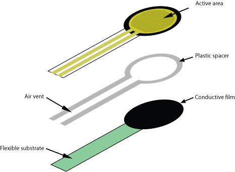
This sensor consists of four layers:
• A layer of dielectric plastic
• An active area consisting of a conductor pattern, which is connected to the cables that will go to the processing circuit.
• A plastic separator, which includes an opening aligned with the active area.
• A flexible substrate coated with a thick polymer conductive film, aligned with the active area. This polymer is most often replaced by an FSR ink layer
![]()
The basic principle for the use of an FSR is a conditioning circuit of the voltage divider type, whereby the output will be an analog volt- age of 0-5 V and varies according to the force exerted on the sensor (SensorWIki, 2016).
Figure 93 shows the connection diagram of a resistive divider or voltage divider. It consists of a voltage source and two resistors connected in series. The current supply will flow through the two resistors evenly because they are connected in this way. One of the two resistors has a variable value, and is that which belongs to the resistive sensor while the other has a fixed value. As explained in this section, an FSR sensor has as its operating principle to decrease the resistance when it increases the force exerted on its surface, which is why it behaves as a variable resistance in the circuit.
![]()
By Ohm's Law, the voltage drop in a load is proportional to the current flowing through it and the resistance it has, and by Kirchoff's Law, the sum of the voltage drops in a circuit is equal to the voltage delivered by the source. When no pressure is applied to the sensor, the top layer and the bottom layer are not in contact, so the resistance is infinite and no current flows through the circuit. As the pressure on the sensor begins to exert force, the two layers mentioned above begin to come into contact and the resistance begins to decrease, whereby current begins to flow through the circuit thus generating voltage drops by the two resistors -tencias (both fixed and variable).
In these sensors, there is a threshold or breaking force that is when the contact between the two layers is sufficient to start running and another step that is saturation, which occurs when the weight increases are very low or no decrease in resistanceSensor construction
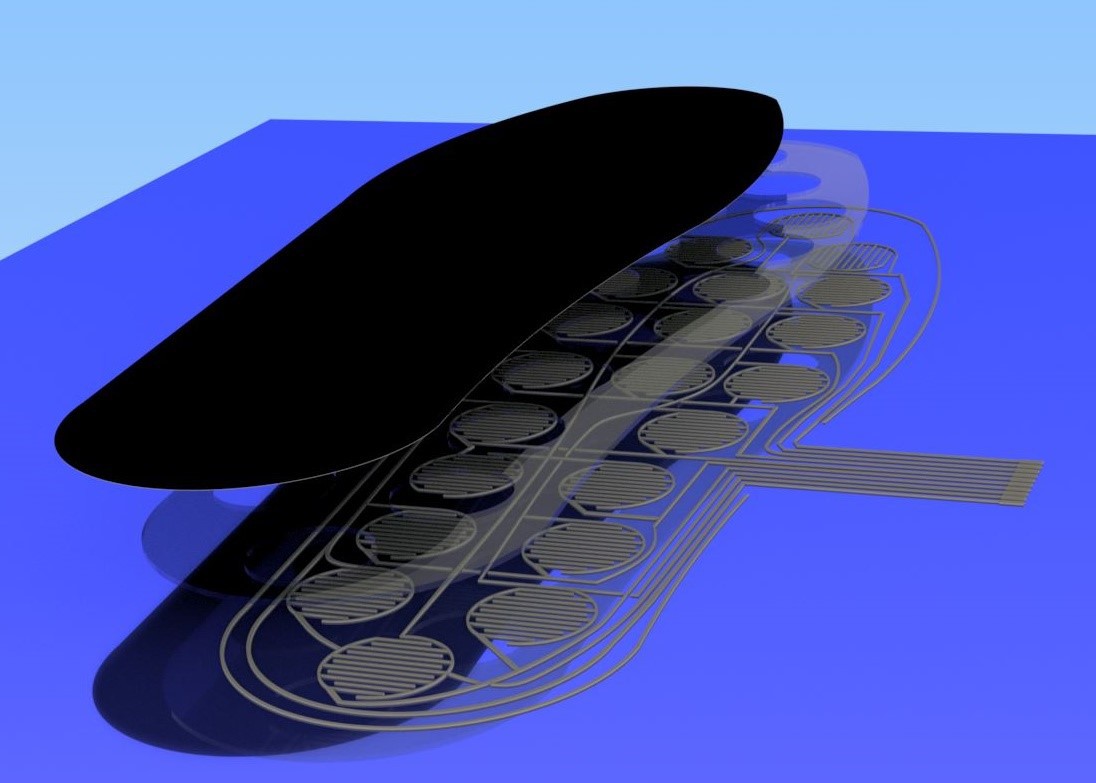
The instrumented insole has a series of layers or plates, each formed by the following stages.
The first layer, is a XactFSR from the company Sensitronics (Senstronics, 2016). It is a plate that has a deposition of carbon on one of its faces, which gives a resistive property to the passage of time. In this way we can obtain an analogue measurement as a function of the pressure exerted on this sheet.
The second layer is a dielectric material that will function as a separator. It has the characteristic of having holes that coincide with the location of the active parts.
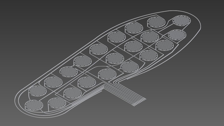
The last layer is an acetate sheet as above. In it are traced silver conductive ink tracks with the selected shape of the sensor. The manufacturer of the XactFSR iron recommends the following specifications for the tracks:
![]()
• The width of the combs and the spaces between them will affect the sensor response. 7mil (.007 ") is a common dimension for both, but other dimensions are viable and may even be desirable depending on the application.
• Sensors with finely spaced fingers will be more sensitive to small forces than sensors with grooved fingers.
• The PCB finish will influence the sensor response. An ENIG (gold) finish is recommended.
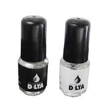
• The thickness of the copper will influence not only the sensor response, but also affect its useful life. When the thickness or weight of the combs are raised copper, will raise the FSR material and increase the deformation of the sensor under load. This deformation allows the blade edges of the copper fingers to penetrate the surface of the FSR material, degrading and eventually destroying it. We have found that copper weights of half an ounce or less, along with the 7-mil finger spacing, produce a good sen- sor response for general purposes and a long shelf lifeFor the elaboration of the sensors, on the sheet of acetate was drawn with conductive ink with silver base. The same is from the electrochemistry DELTA® and is easily achieved in local businesses of electronic components. It is generally used for the repair of printed circuits and flexible cables, and is formed by a dispersion of silver in flakes seated in a synthetic substrate of great flexibility. Its application can be on glass, ceramics, flat cables, plastics, rubber, among others. It can be purchased in containers of 6/16/30/60 grams, which come with a brush for its application as well as with a solvent of fast evaporation that avoids the cracking of the paint after its placement, it is also used to restore the original viscosity, as well as for cleaning the brush. It has the property of being flammable.
Among the physical properties of this paint, the manufacturer indicates that the average particle size is 23 microns and has a specific gravity of 9.3 g / cc![]()
Due to retraction problems, which caused the residual ink to be spread through areas where it was not due, it was decided to use one with the capacity to retract the syringe plunger.
It was obtained from the Thingiverse page, and for the construction it was necessary:
• The three printed parts
• Rod M5
• NEMA 17 engine
• 8mm smooth rod
• Two LM8UU bearings
• Flexible coupling 5mm to M5
• 7 M3 screws
• 7 M3 nuts
• 1 Ml. Syringe sleeve.
• 1 Anti damping for the engine
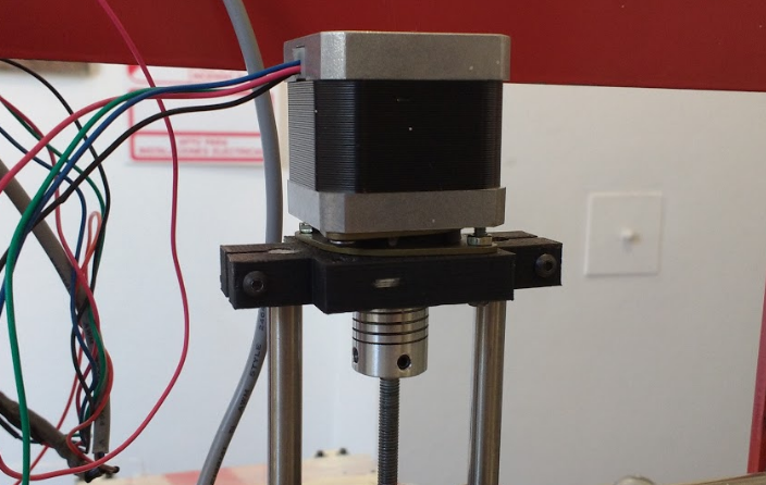
The first printed part is static and has the function of fixing the motor. It transmits the movement through a threaded rod M5 by means of a flexible coupling that allows the mobility of the rod in case of an imperfection and is not completely straight, thus avoiding the transmission of the error to the car and reducing the vibrations. On the sides, were the smooth rods that allow the displacement of the rolling. LM8UU bearings are used to minimize friction and do not affect the translatory movement of the carriage. Originally the design did not contemplate them, for that it was necessary to make the corresponding adaptations.
![]()
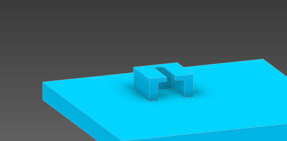
First printed part of the extruder with retraction
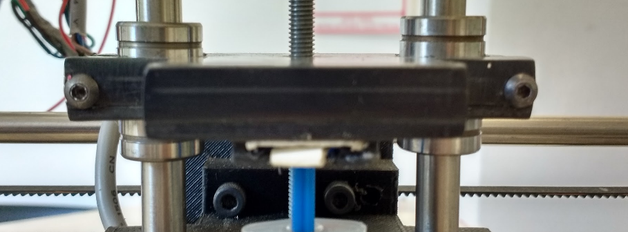
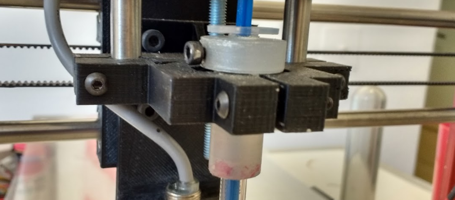
The second printed part, is the only moving part of this structure, called carriage. The part slides on the smooth rods using linear bearings LM8UU. The transmission of the movement is achieved by the interaction of the threaded rod with a nut M5 recessed in this piece. The direction of rotation of the motor determines the direction of movement.
In its lower part it has a support where the plunger is imprisoned, so that this content and can avoid descending or ascending movements. It is very important that the plunger is perfectly supported without the possibility of free movement, if this happens, a backslash will occur which would result in improper extrusion or retraction.![]()
Illustration 43: Lower piston support![]()
Illustration 44: Pulver Extruder Truck With Retraction
The last piece printed, where the syringe was contained, is the one that marks the end of the extrusion when the lower part of the bearing makes contact with it.
![]()
Illustration 45: Third and last printed part of the extruded pasta extruder
The extruder was adapted for a 20 Ml syringe. but due to the fact that it was higher than the amount needed, a case was adapted to be able to place the 1 Ml syringe. finally used.
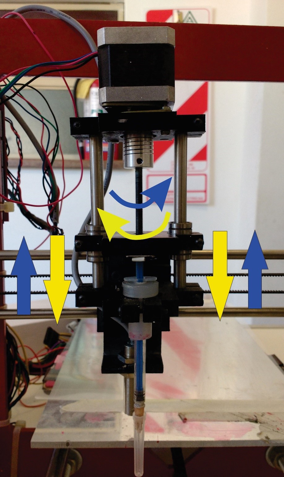
The extruder operates by transmitting the engine rotations to the rod by means of the coupling to achieve movement of the centerpiece, the operation of which has been described above. The direction of rotation will indicate the direction of movement and final result of the mechanism: the clockwise rotation produces a downward movement and consequently an extrusion, while the anti-clockwise produces the opposite![]()
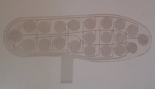
Once the active region of the sensors was obtained, the other two layers were designed and cut. For the separator, the design was vectorized and cut by laser. On the other hand, the XactFSR sheet was cut manually so that there was no risk of altering the physical properties of the material.
![]()
![]()
 Facundo Noya
 The second version incorporate a tp4056 for lipo battery and HM-10 Ble module
