-
1Block diagram - initial prototype
I've described much of the build process in the update logs, so I'll use this section for block diagrams showing the wiring connections.
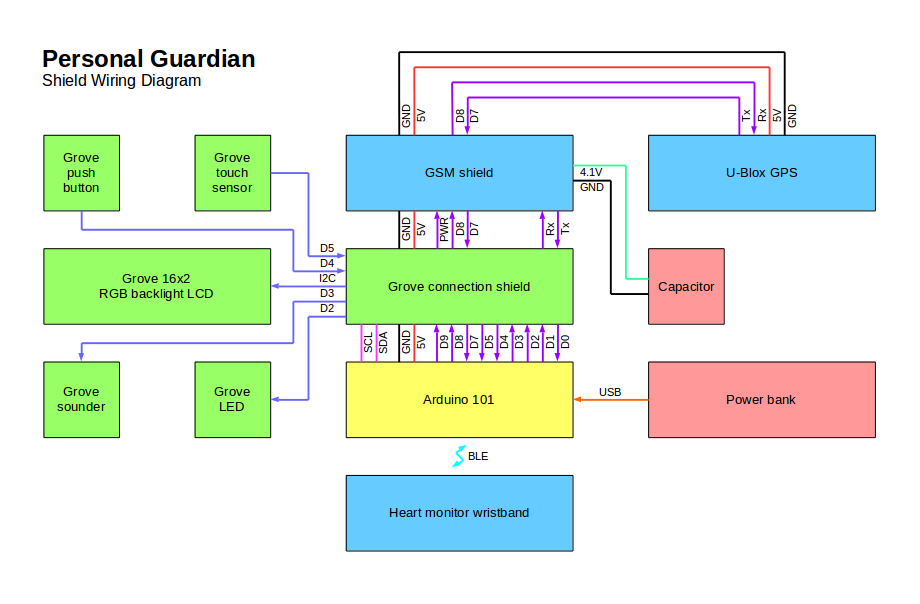
Here is a block diagram of the initial development version, using the Grove interface shield:
![]()
-
2Block diagram - final design
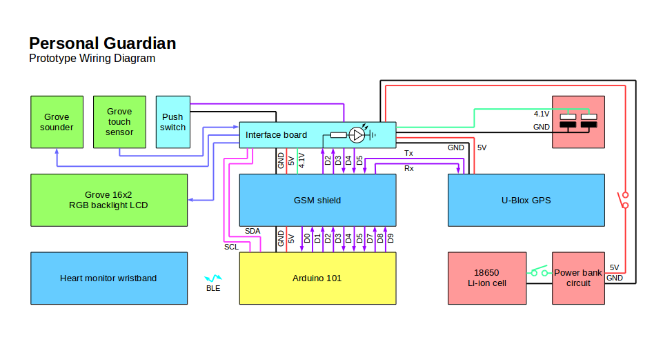
With the matrix interface board replacing the Grove shield, and with the power bank internal parts removed and placed in the housing, the updated block diagram represents the final design:
![]()
-
3Software
The software is a single sketch for the Arduino IDE. I have uploaded it here as an attached file. You are free to use the software for any non-commercial use.
Important - when I made the interface board, I changed the polarity of the pushbutton, which is active low as defined in the final software. If you build the shield version, you will need to either change the software to look for an active high button, or use a button that is active low (unlike the Grove starter kit button, which is active high).
Personal Guardian
A wearable device to allow vulnerable people to maintain their independence, by providing a safety link with a remote carer.
Discussions
Become a Hackaday.io Member
Create an account to leave a comment. Already have an account? Log In.