-
Example screens
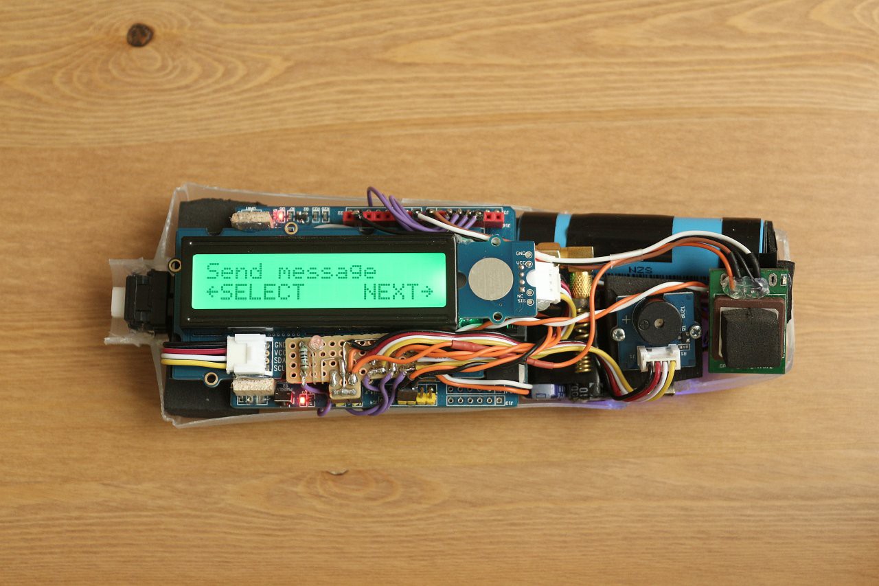
09/03/2017 at 17:25 • 0 commentsHere are some pictures of the device in operation, showing the use of the RGB backlight for status feedback. Here is the menu option for sending a text:
![]()
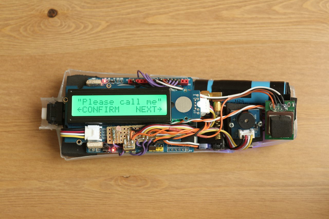
And the user can select one of several predefined messages:
![]()
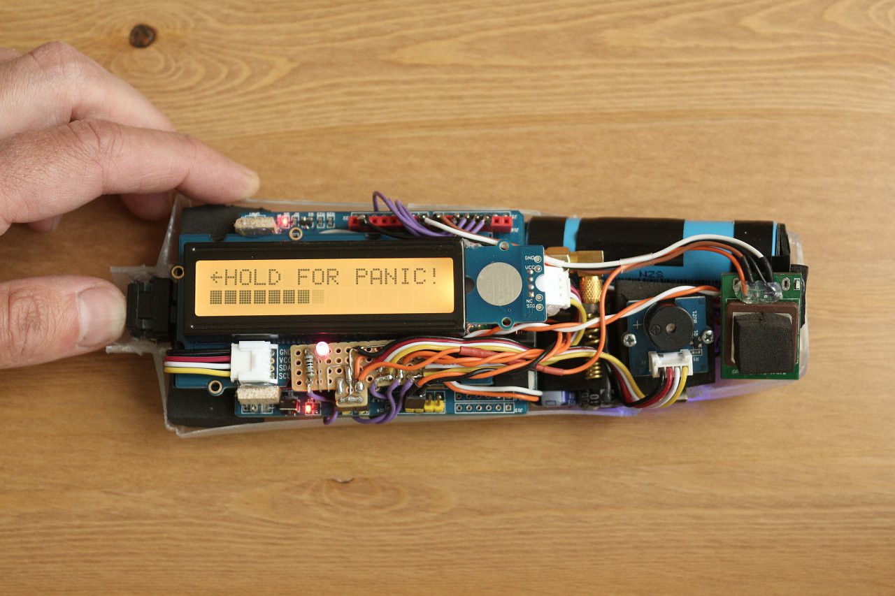
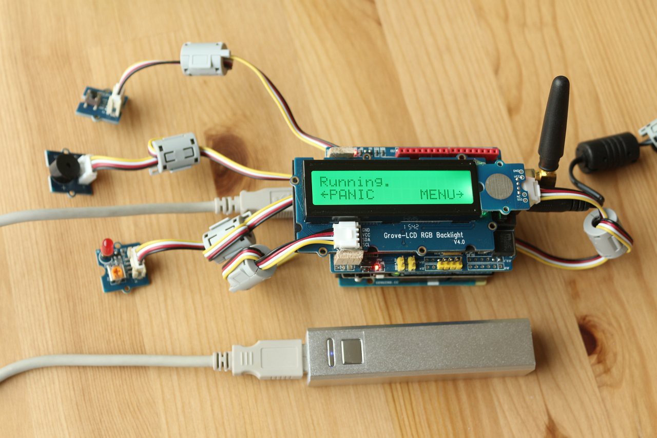
The panic function is activated by holding the button down for 2 seconds:
![]()
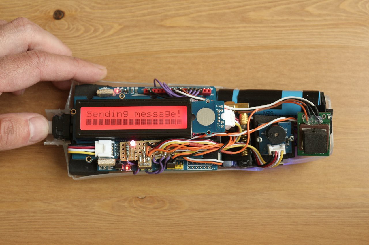
A red screen confirms the activation and the device sends a message to the carer:
![]()
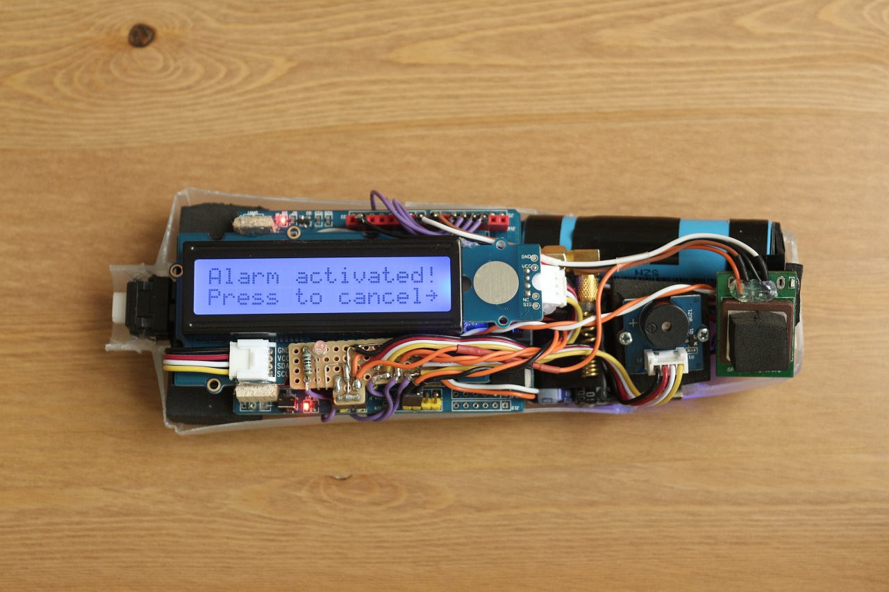
The screen then strobes alternately red and blue, and an alarm sounds, to draw attention to the user. It can be cancelled by pressing on the touch sensor:
![]()
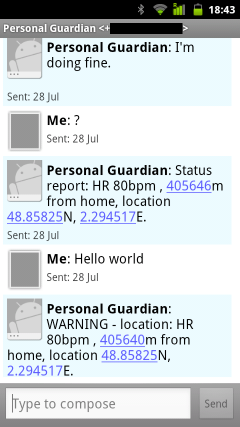
Here is a phone screenshot showing a text conversation with the device. The location is faked for the purposes of this screenshot, but the calculated distance from this fake location is genuine. As a result, the device sent an alert due to the large distance from home (the first status report visible is in response to the query '?', the second came automatically the next time the device was powered on):
![]()
During the fall detection, the screen turns orange in freefall, and then red after the impact. If the user cancels the warning, the screen returns to green.
![]()
-
Step 5 - wearable housing
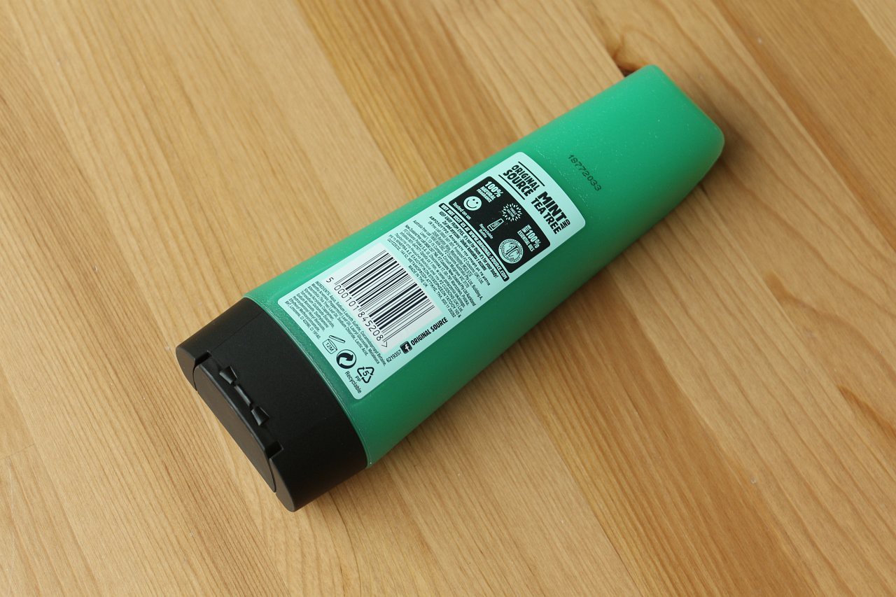
09/03/2017 at 16:49 • 0 commentsI found a suitable housing for the device, which is an optimum size to hold all the components and has rounded edges suitable for a wearable device. It also has a pleasant scent of mint and tea tree and it looks like this:
![]()
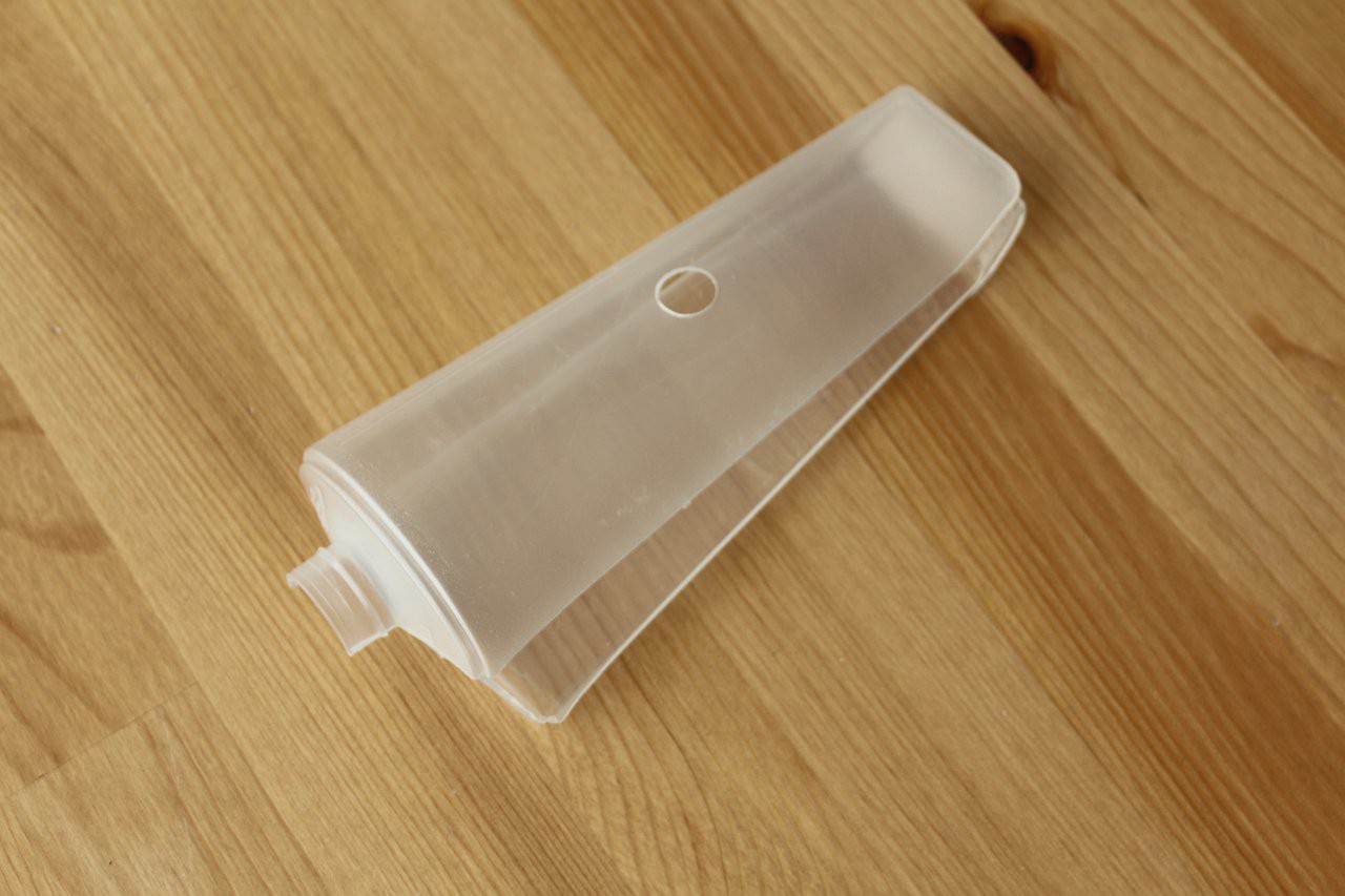
As a bonus it came with some free shower gel inside! I used that up first before continuing. Then I cut the housing in half and added cutouts for the LCD and touch sensor. The panic button will fit into the opening where the cap was:
![]()
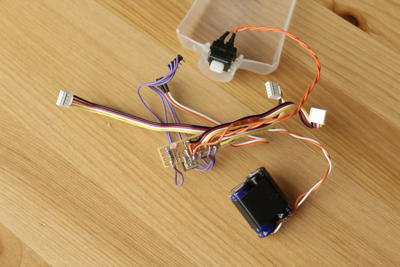
The stack of boards was really too large to fit, so I decided to eliminate the Grove interface shield, which was just connecting bits together. I used a small piece of matrix board as a replacement, with flying leads to plug into the Arduino headers. This board includes the LED, the capacitance for the GSM board power (two electrolytic capacitors in parallel) and the wiring to the panic button, as well as the connectors for the LCD, touch sensor and sounder. Here it is, with the panic button attached and glued into the housing:
![]()
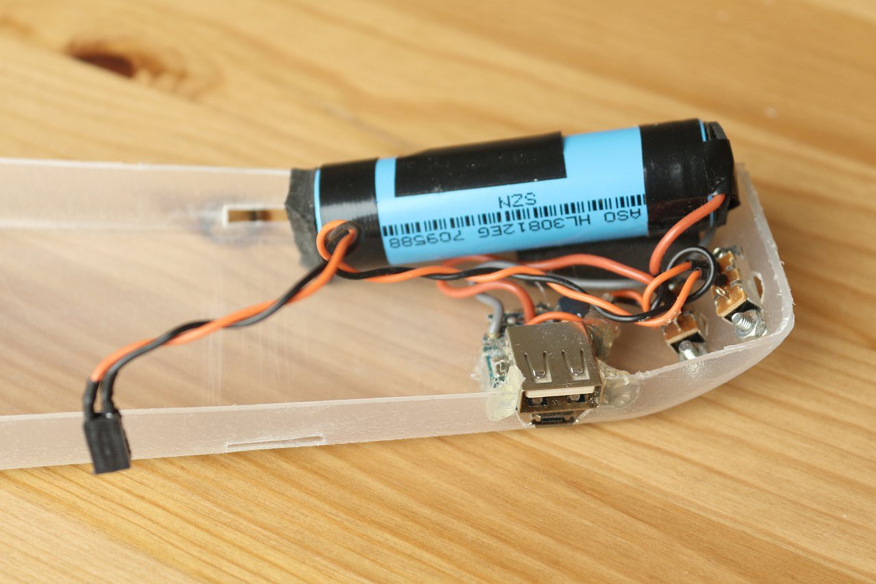
Here are the internals of the power bank fitted into the housing. I added two switches - one to disconnect the cell, and one to switch the device on and off. The power bank circuit has a push button to activate it, and this protrudes from the bottom of the housing. The USB connectors are accessible at the side, to allow the device to be charged up.
![]()
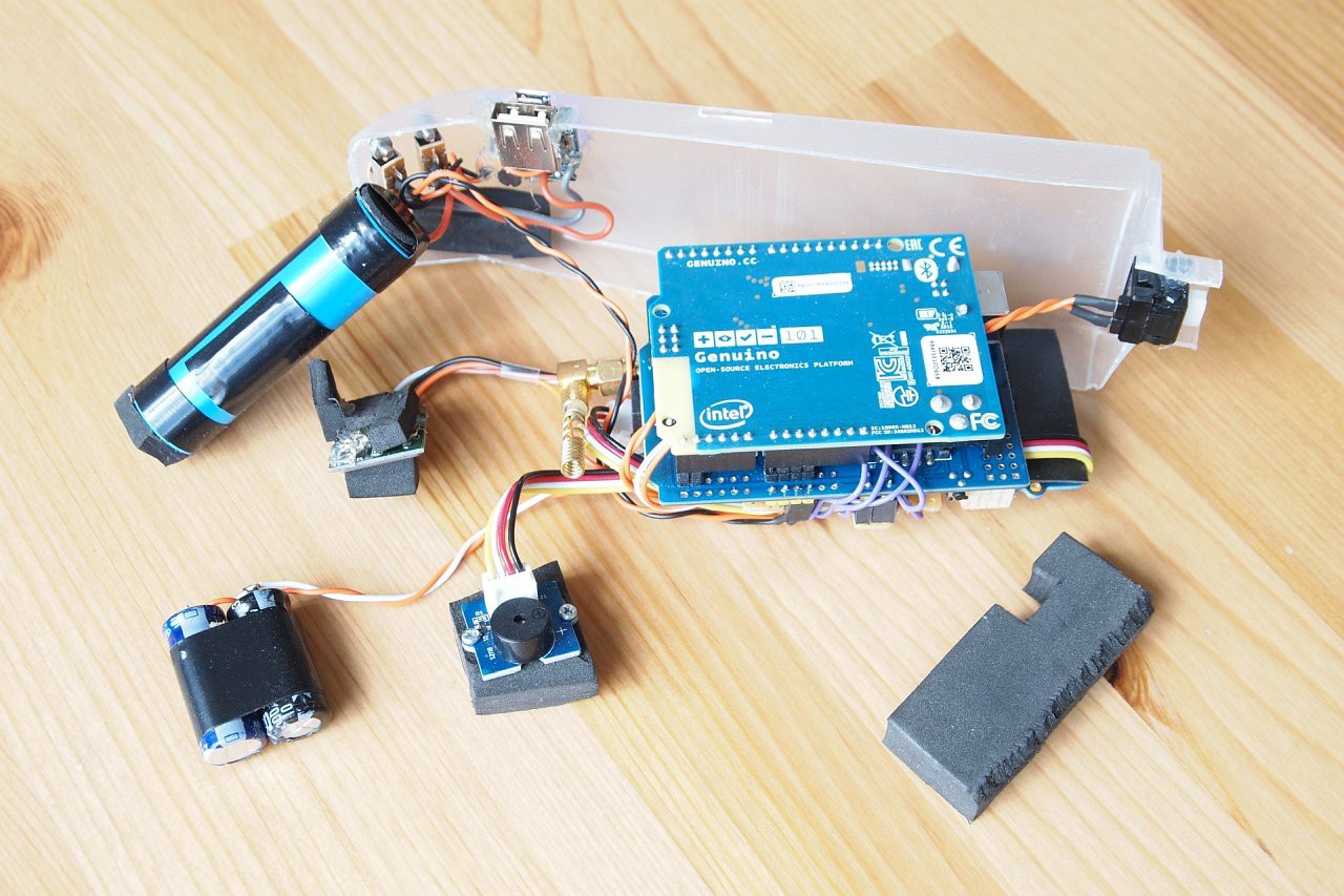
Here is the newly slimmed-down stack of boards connected up and ready to fit into the housing, with some pieces of foam rubber to allow a snug fit:
![]()
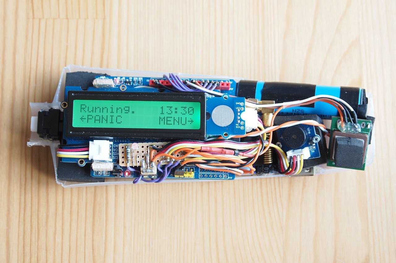
Now everything is in place - to get the GSM antenna to fit I removed the plastic cover:
![]()
And finally with the lid on, held in place with velcro straps that double as attachment straps for wearing the device:
![]()
And a view underneath:
![]()
Everything fits surprisingly well! To wear the device, it can be attached to the upper arm, like this:
![]()
Alternatively, the housing is slim enough for the device to go into a trouser pocket, and this is a bit less intrusive. The fall detection works with the device in either location.
Now everything is in place, and all that remains is to fine-tune the software and try to figure out the BLE heartrate measurement, or get a different heart rate monitor! Here is the M2 strap making a measurement triggered by the device via BLE - if only I could read the result:
![]()
-
Step 4 - GPS
09/02/2017 at 21:52 • 0 commentsTo allow the device to track the user's location, I could have used a GPS shield, but I was concerned that the unit was getting too big to be wearable. An alternative is a GPS USB stick, which is physically much smaller than a shield. USB is generally not the most convenient method of connecting something to an Arduino, but luckily most GPS chipsets support serial comms - the challenge is to access these pins, and not use USB at all.
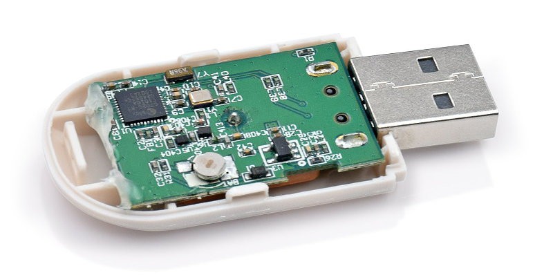
I bought a U-Blox VK-172 GPS USB stick like this one. Inside, it looks like this:
![]()
The chip at the top left of the picture is the UBX-G7020. The capabilities are amazing considering that the complete stick cost $7 - GPS and GLONASS support, 56 channels, 10Hz update rate and 1 second hot start acquisition. There is even a coin cell battery to retain the ephemeris data.
I found the hardware integration manual for the UBX-G7020 here. It is all very interesting but the main point is that the serial Rx and Tx lines are provided on pins 18 and 19, at 3.3V level, and the default baud rate is 9600.
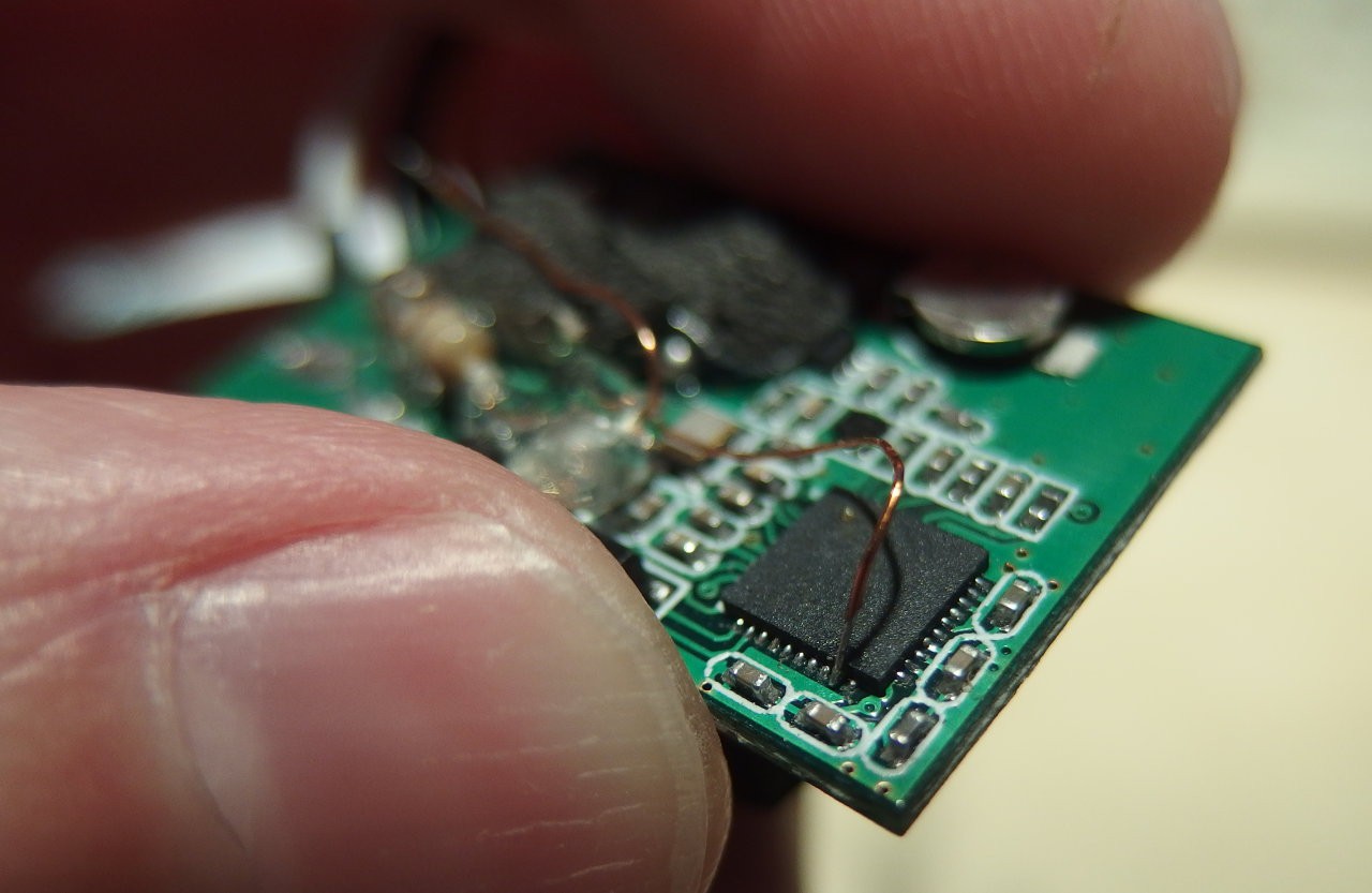
To use the board I simply desoldered the USB connector and discarded the plastic housing. Then I soldered two wires on to pins 18 and 19 of the UBX chip, added 100 ohm series resistors, and connected them to pins 8 and 7 of the Arduino (in this way the voltage levels are compatible). To communicate I used the software serial library with pin 7 as Rx and 8 as Tx.
Here's the first wire soldered on - this is 34swg (0.236mm) enamelled wire (the chip is a QFN-40 package, which is 5mm along one side):
![]()
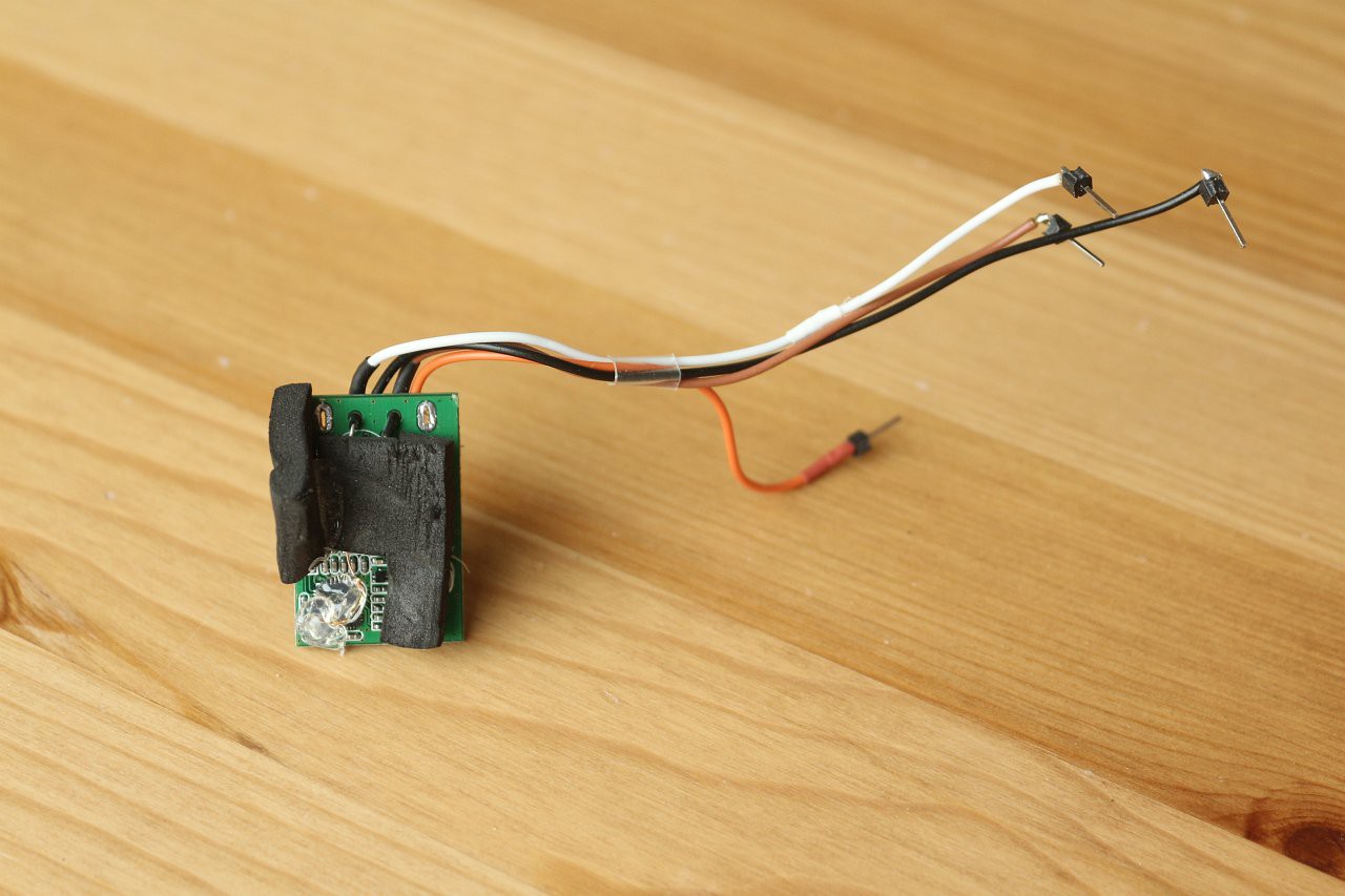
+5V and ground wires can be soldered to the board at the pads where the USB connector originally was. To add some mechanical protection I covered the soldered wires with hot melt glue. Then I added flying leads with pins attached, to allow the board to be plugged in to the Arduino headers:
![]()
The black stuff is some foam rubber I glued on to allow the board to fit nicely into the case (see later).
As it happens, in the software I never send any commands to the GPS board, I only listen to the data, and the default configuration provides everything needed. The location information is provided in the standard NMEA format (various other settings are possible as well).
To parse the NMEA data I'm using the really excellent TinyGPS++ library written by Mikal Hart. This library "just works" with almost no coding required at all, and makes it really easy to get position and speed information as well as find the distance from a fixed point, like this:
gnssDistance=(unsigned int)(gnss.distanceBetween(gnss.location.lat(),gnss.location.lng(),HOME_LAT,HOME_LNG));So there's a simple and cheap way to add GPS functionality to an Arduino device, and I will definitely use the same hardware/software combination in the future!
With all the functionality in place, the next step will be to fit the device into a suitable housing.
-
Step 3 - IMU and BLE functions
09/02/2017 at 00:10 • 0 commentsIMU functions
The Arduino 101 Inertial Measurement Unit is fully documented and works well. For the fall detection, the software detects a short period of freefall followed by a shock. Both events are handled via callbacks:
void imuInit(void) {
  // Initialise the IMU
  lcd.setCursor(0,1);
  lcd.print("Starting IMU... ");
  CurieIMU.begin();
  CurieIMU.setAccelerometerRange(4);
  CurieIMU.attachInterrupt(imuCallback);
  // Enable Freefall Detection
  CurieIMU.setDetectionThreshold(CURIE_IMU_FREEFALL,500);
  CurieIMU.setDetectionDuration(CURIE_IMU_FREEFALL,50); //ms
  CurieIMU.interrupts(CURIE_IMU_FREEFALL);
  // Enable Shock Detection
  CurieIMU.setDetectionThreshold(CURIE_IMU_SHOCK,500); //mg
  CurieIMU.setDetectionDuration(CURIE_IMU_SHOCK,20); //ms
  CurieIMU.interrupts(CURIE_IMU_SHOCK);
}
// IMU Callback
static void imuCallback(void) {
  if(CurieIMU.getInterruptStatus(CURIE_IMU_SHOCK)) {
    if(falling) {
      lcd.setRGB(255,0,0);
      fallEvent=true;
    }
  }
  if(CurieIMU.getInterruptStatus(CURIE_IMU_FREEFALL)) {
    if(!fallEvent) lcd.setRGB(255,128,0);
    falling=true;
    lcdTimeout=fallTimeout=millis();
  }
}
When the freefall begins, the LCD colour is set to orange. If a shock subsequently happens within a certain timeout period, the LCD colour changes to red and an alarm is triggered. An emergency text message will be sent unless the user presses a button to cancel it. These functions are handled by the main code polling loop.
BLE functions
Implementing the Bluetooth functions involved a bit more effort! The first step was to acquire a BLE heart rate monitor. There is a huge variety available, so it was pot luck whether the one I chose would be easy to use or not. It turned out to be... not.
Bingo M2
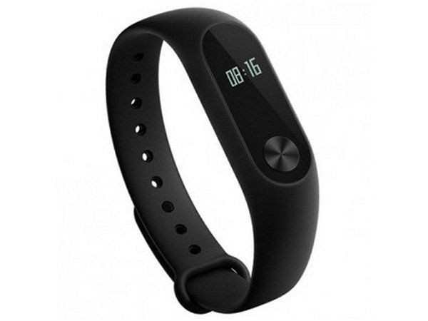
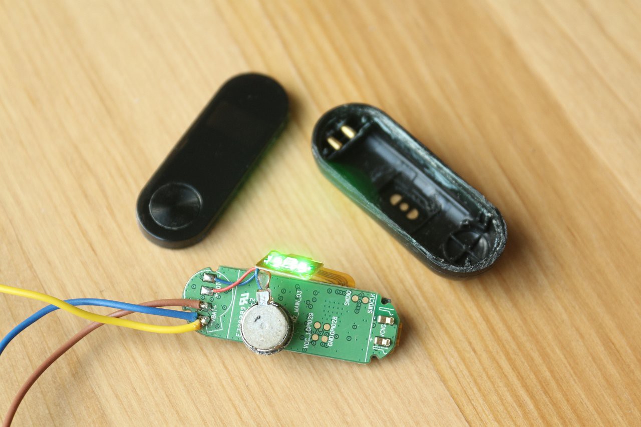
The device I got from China via ebay is the Bingo M2. As far as I can tell, this seems to be an Indian copy of the Xiaomi Mi Band 2. The latter seems to be a fairly decent low cost device, whereas the former, even cheaper device has some rather dubious features.
![]()
Firstly, when I received the M2 it was completely dead. It comes with a USB adaptor for charging, but plugging it in did nothing. I decided to cut it open and see what was inside.
![]()
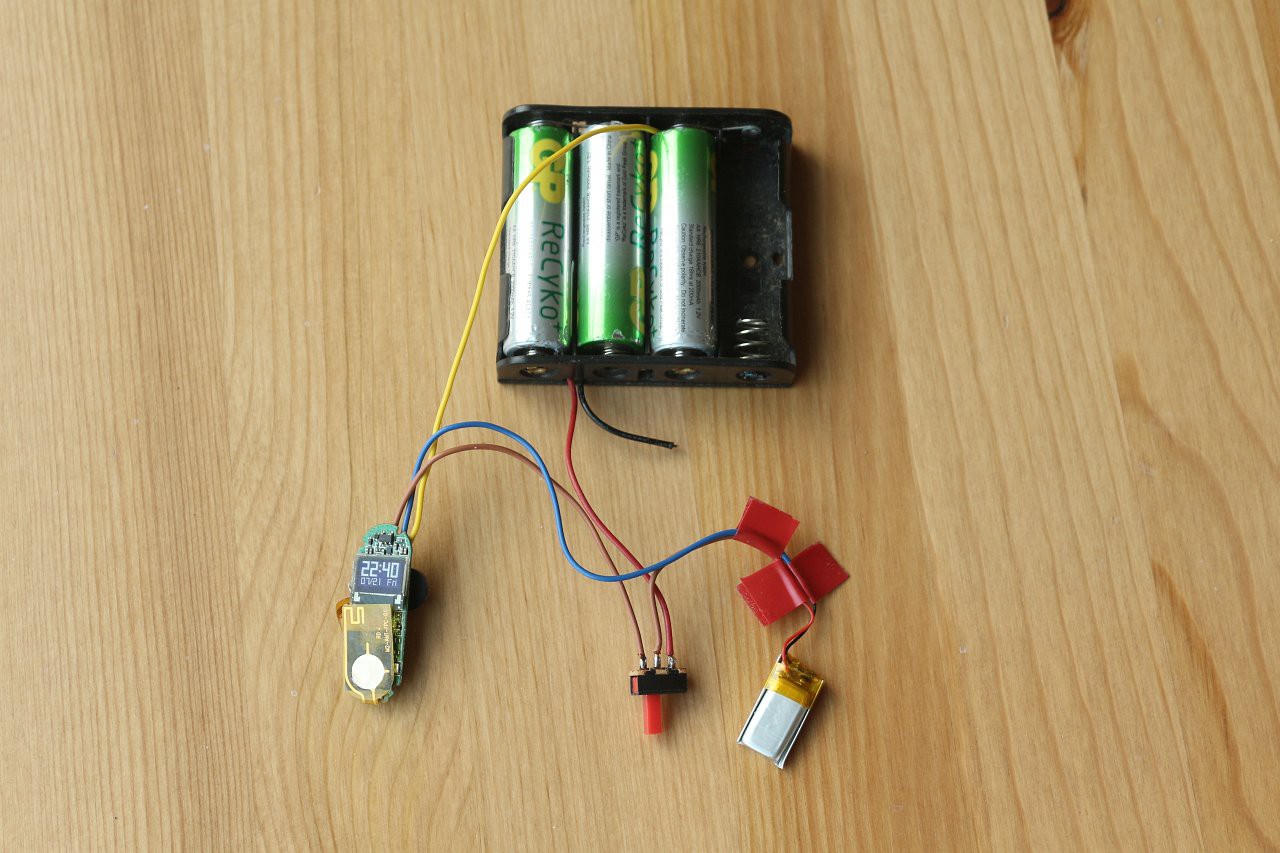
As well as the circuit board, vibration motor and pulse sensor, it contained a small Li-poly cell that measured about 2V. It seems that at such a low voltage, the charge circuitry doesn't work, which is a bit of a design flaw.
I connected up some AA cells as a rudimentary battery charger (note: use a resistor), and with the cell charged up to 3V it started to work (and the charger subsequently worked as well).
![]()
Now came the task of interfacing to it. Most of the BLE examples for the Arduino 101 configure it as a peripheral (providing a service), but in this case I wanted to act as a central (client) device. Luckily there are some examples of how to do this here. With the PeripheralExplorer example, the M2 showed up and announced its services. Success!
Er, not quite. Unfortunately the M2 does not support the standard BLE heart rate service with UUID 0x180D. In fact it has a proprietary, undocumented interface. Although I could figure out how to read the step count from the device, trigger a notification or vibration and even start a heart rate measurement (turning the sensor LEDs on), I couldn't work out how to read the heart rate result.
Looking at the code of the official Droihealth app, it seems that the heart rate result will be provided in a UUID that is not visible in the initial BLE service scan, but only provided after triggering a measurement. I could not find out how to read this new UUID with the Arduino 101 BLE implementation. Eventually I gave up, because in any case the heart rate measurements of this device (when triggered manually) don't seem to correlate in any way with the user's actual heart rate. Whether the heart rate is fast or slow, or the device is sitting on the table, the heart rate always seems to be 89. It might be just my device, or it might be a good idea to try a different device...
So, for now, the software just assumes a heart rate of 80, and the heart rate monitoring feature is not working. The wrist strap is still used to provide vibration notification when a text message is received, and the measurement is triggered by the software periodically (so the sensor LEDs illuminate), but sadly no measurement is forthcoming.
The next step will hopefully be more likely to succeed - the integration of the GPS sensor.
-
Step 2: Software and SMS functionality
09/01/2017 at 23:05 • 0 commentsIDE installation
Initially I had a problem with the IDE (on 64-bit Ubuntu 16.04) in that I couldn't connect to the board at all. It turns out that you have to manually run a script to set USB permissions, and the location of this script is not as documented. I had to do this:
sudo ~/.arduino15/packages/Intel/hardware/arc32/2.0.2/scripts/create_dfu_udev_rule
After this, everything ran smoothly! I wrote the code to implement a basic menu controlled by the two buttons (the pushbutton and touch sensor), and I used the serial console to display debugging information.
Here is the stack with power connected and the LCD backlight set to green:
![]()
At the top level menu screen, the push button acts as a panic switch and the touch sensor cycles through the menu options. When cycling through the options, the push button selects a menu item. The lower line of the LCD makes it clear what each button will do.
Power problems and solutions
The GSM shield can draw quite some current when transmitting (about 2A for short periods). The shield has a regulator to provide the 4.1V supply for the SIM900, and a power jack for an external adaptor that feeds this regulator. This external adaptor is fine for testing, but won't be much use for a wearable device.
There is a switch on the shield that can be used to feed the regulator from the Arduino 5V pins instead of the external jack, but the current available is not enough to support the transient peaks. I found that the SIM900 would frequently reset due to lack of power. Luckily, I found an easy solution. By adding a large electrolytic capacitor on the 4.1V line, the transients can be supported and the shield will operate fine from the Arduino 5V supply. I found that 4700uF was ample. The MIC29302 regulator doesn't seem to mind the extra capacitance on the output.
The power architecture of the Arduino 101 supports various possibilities for powering the board, including power from the external jack, the USB interface and also a direct feed on the 5V pins. Looking at the schematic, it seems to me that low dropout protection devices prevent any backfeed damage. I plan to provide 5V via this direct method, and this will also feed the GSM shield regulator.
USB power bank
The source of 5V will be a USB power bank. This provides a neat solution as it integrates a 3.7V Li-ion cell with a power supply circuit and charger, and will allow the device to be charged up with a USB cable.
Here is the project so far, with the Arduino powered by the USB power bank. At this stage the GSM shield still has external power, as the capacitor is not yet connected. The LCD is showing the top level menu screen, with custom defined arrow icons:
![]()
GSM functions
I bought a pre-paid SIM card that offered free texts to the same network as my mobile phone. This is helpful as you can end up sending a lot of texts during development.
I found the following SIM900 references very useful:
It turns out that sending and receiving text messages in a basic way is really quite easy. The SIM card contains a few memory slots for received text messages. You can either poll the SIM900 to see if a new message has arrived in one of the slots, or you can ask to be notified when a new message arrives. I chose to poll for new messages, and the software does this every 60 seconds. If a new message has arrived, it is read and then deleted from the SIM card.
Sending a text message is simply a case of sending one AT command followed by the destination phone number and the actual message. Here is the complete function for sending a text, with the GSM shield connected to Serial1, and noting that gsmWait() simply waits until the Serial1 receive buffer is empty:
bool gsmSendSMS(int n) {
  bool result=false;
  Serial.print("Sending SMS ");
  Serial.println(n);
  Serial1.print("AT+CMGS=\"");
  Serial1.print(MOBILE_NUMBER);
  Serial1.println("\"");
  if(gsmWait()) {
    if(n==REPORT) Serial1.print("Status report");
    if(n==REPORT+1) Serial1.print("WARNING - PANIC pressed");
    if(n==REPORT+2) Serial1.print("WARNING - heart rate");
    if(n==REPORT+3) Serial1.print("WARNING - location");
    if(n==REPORT+4) Serial1.print("WARNING - fall detected");
    if(n>=REPORT) {
      Serial1.print(": HR ");
      Serial1.print(heartRate);
      Serial1.print("bpm , ");
      Serial1.print(gnssDistance);
      Serial1.print("m from home, location ");
      if(gnss.location.rawLat().negative) Serial1.print("-");
      Serial1.print(gnss.location.rawLat().deg);
      Serial1.print(".");
      Serial1.print(gnss.location.rawLat().billionths);
      Serial1.print("N, ");
      if(gnss.location.rawLng().negative) Serial1.print("-");
      Serial1.print(gnss.location.rawLng().deg);
      Serial1.print(".");
      Serial1.print(gnss.location.rawLng().billionths);
      Serial1.print("E.");
    }
    else {
      Serial1.print(TEXTMESSAGE[n]);
      Serial1.println(".");
    }

    Serial1.println((char)26);
    result=gsmWait();
  }
  else {
    Serial.print("Unable to send SMS");
    Serial1.println((char)26);
  }
  return result;
}
I decided to keep the messaging implementation very simple. The carer's phone number is currently hard-coded in the software, and there are several pre-defined messages that the user can select to be sent. Received messages are checked to see if the first character is a question mark '?', and if it is then the device will send a status response. If not, the message will be displayed on the LCD as a scrolltext. If a new message comes in, the previous scrolltext is overwritten.
The next step will be to add the heart rate monitor and fall detection functions.
-
Step 1: Assembly of the main components
09/01/2017 at 22:08 • 0 commentsTrial assembly
I started by obtaining all the basic components and plugging them together. The Arduino design concept makes it really easy to build up a fairly complex design without any soldering, and it should just work. So I was hoping that this would prove to be the case!
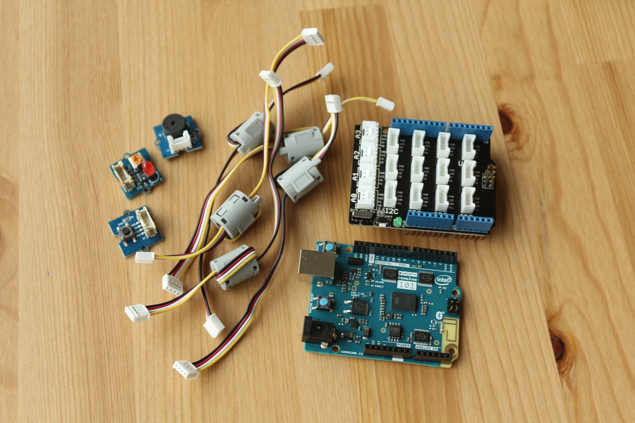
The Grove starter kit consists of several useful parts and an interface shield to connect them all together. I wanted to use several of these components, including the 16x2 LCD, which has a nice RGB backlight that I could use to indicate the device status. There is also a touch sensor that I wanted to try out as a button for the user interface.
Here is the Arduino 101 with the Grove interface shield and the sounder, LED and pushbutton components, with connecting cables:
![]()
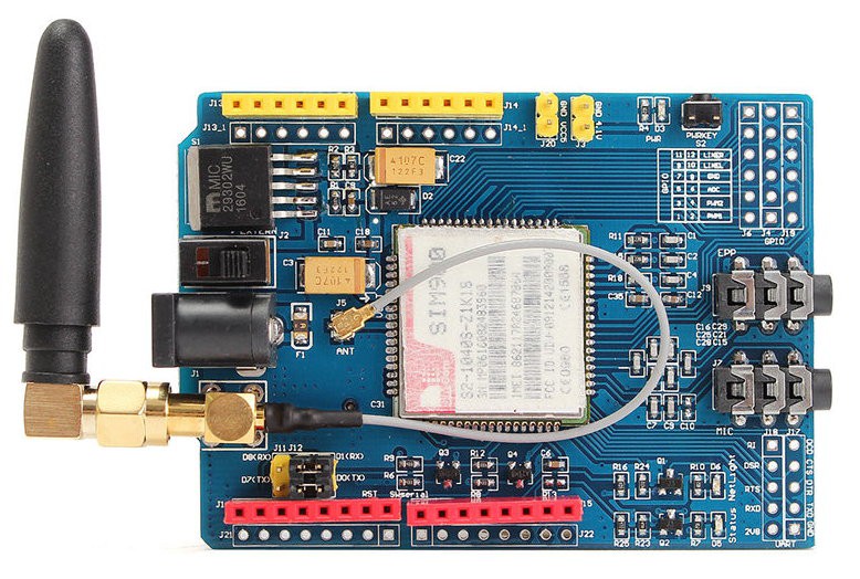
And I got this SIM900 shield from ebay - it seems to be a common design:
![]()
Preparation of the GSM shield
Before using the GSM shield I had to do some preparation of the board, because the pin headers were not fitted. I decided to populate just the pins that were needed. After reading up about the Arduino serial interface, I discovered that the Arduino 101 has two hardware serial interfaces, and the one used for programming is different from the one available on D0/D1, so there is no conflict. I decided therefore to use D0/D1 for the GSM shield, and avoid software serial, which apparently can sometimes be problematic.
In addition to D0/D1 for the serial pins. D9 is used to power the shield on. I found that my board had an open jumper on the board that I needed to solder to connect this D9 line. In the image above it's visible just above the last two pins on the right of the row of red pin headers.
To allow things to fit together better, I relocated the block of serial selection jumpers from the top to the bottom of the board.
Stacking the boards
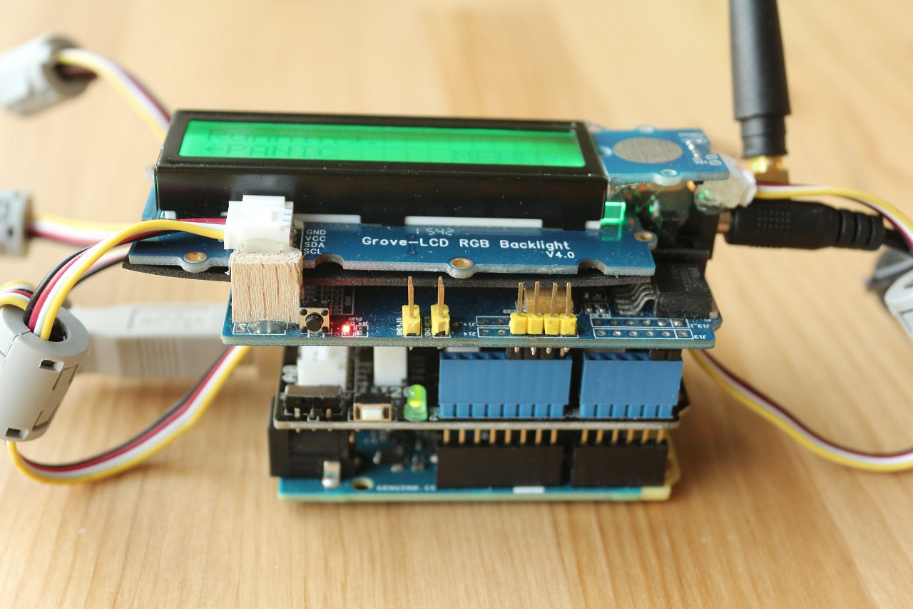
The GSM shield had to go on top of the stack of boards, as it doesn't carry the IIC pins that are needed for the interface shield. I decided to attach the 16x2 LCD and touch sensor on top of the GSM shield, to make a compact block. The LCD fitted neatly once the serial jumpers on the GSM shield had been relocated. To attach the parts I used hot melt glue and some small balsa wood standoffs. In between the LCD and GSM shield is a piece of rubber sheet to prevent any short circuits between the boards.
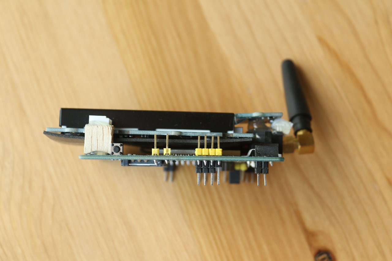
Here is the GSM shield with the LCD and touch sensor firmly attached:
![]()
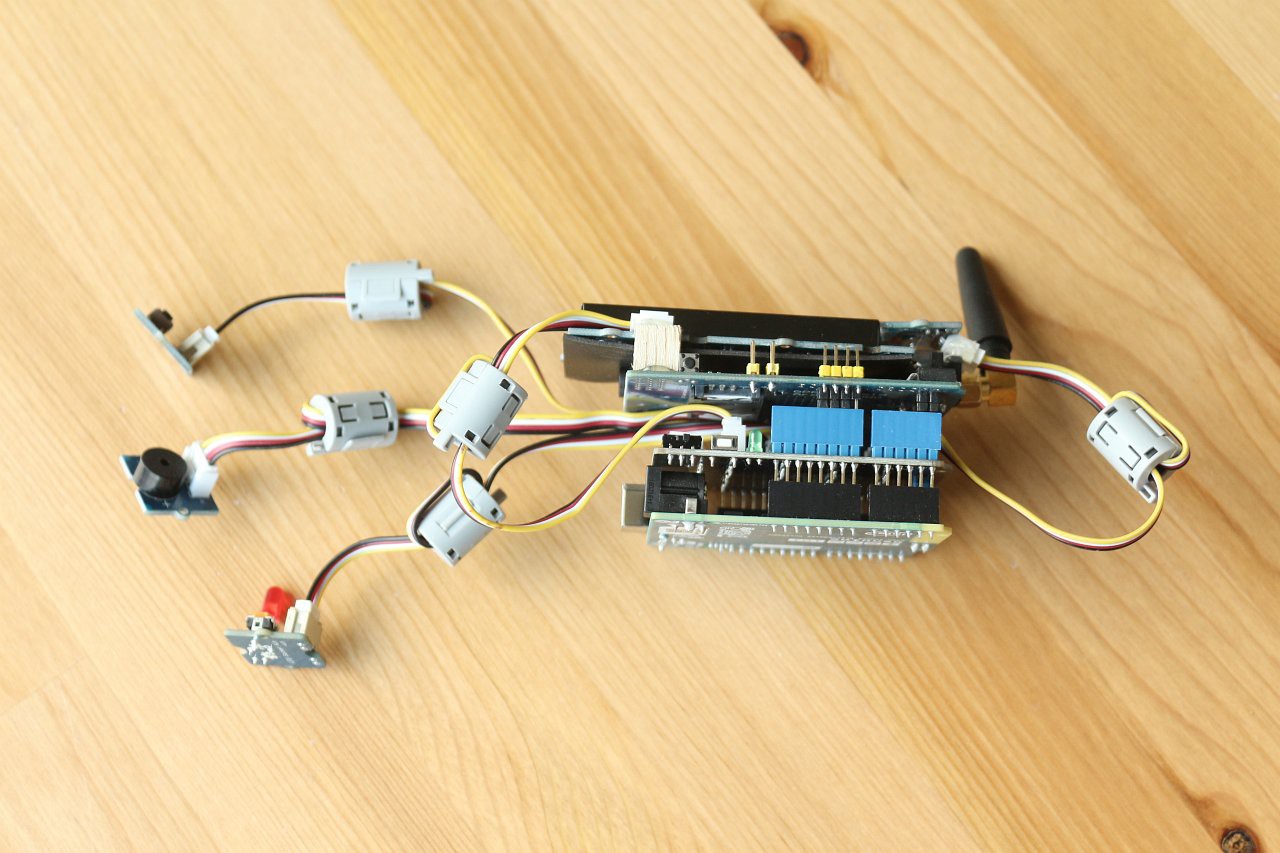
Finally, here is the complete stack, consisting of Arduino, Grove interface, GSM shield, LCD, touch sensor, pushbutton, LED and sounder. For a portable device it is looking rather tall:
![]()
The next step was to connect the power, install the Arduino IDE and start writing some software!
Personal Guardian
A wearable device to allow vulnerable people to maintain their independence, by providing a safety link with a remote carer.