deʃhipu
-
LED Matrix Shield Done
10/18/2017 at 17:47 • 0 commentsToday I sat down and wrote the CircuitPython driver for the IS31FL3728 chip that I used for this shield. The effect looks as expected:
![]()
The code is rather simple too:
class Matrix7x5: _ROWS = (3, 2, 4, 1, 0) _COLS = (6, 5, 0, 4, 1, 2, 3) _word = bytearray(2) def __init__(self, i2c, address=0x60): self.i2c = i2c self.address = address self.buffer = bytearray(8) self._config_register = 0 self._effect_register = 0 def _register(self, register, value): self._word[0] = register self._word[1] = value self.i2c.writeto(self.address, self._word) def fill(self, color=1): color = 0xff if color else 0x00 for y in range(8): self.buffer[y] = color def pixel(self, x, y, color=None): if not (0 <= x <= 6 and 0 <= y <= 4): return x, y = self._COLS[x], self._ROWS[y] if color is None: return bool(self.buffer[x] & (0x01 << y)) elif color: self.buffer[x] |= 0x01 << y else: self.buffer[x] &= ~(0x01 << y) def show(self): for y, row in enumerate(self.buffer): self._register(0x01 + y, row) self._register(0x0c, 0xff) def brightness(self, value): if value is None: value = self._effect_register & 0x0f if value & 0b1000: value &= 0b0111 else: value += 7 return value elif (0 <= value <= 6): self._effect_register = ( self._effect_register & ~0x0f | (0b1000 | value) & 0x0f) elif (7 <= value <= 14): self._effect_register = ( self._effect_register & ~0x0f | (value - 7) & 0x0f) else: raise ValueError("out of range") self._register(0x0d, self._effect_register) def active(self, value=None): if value is None: return bool(self._config_register & 0x80) if value: self._config_register |= 0x80 else: self._config_register &= ~0x80 self._register(0x00, self._config_register) -
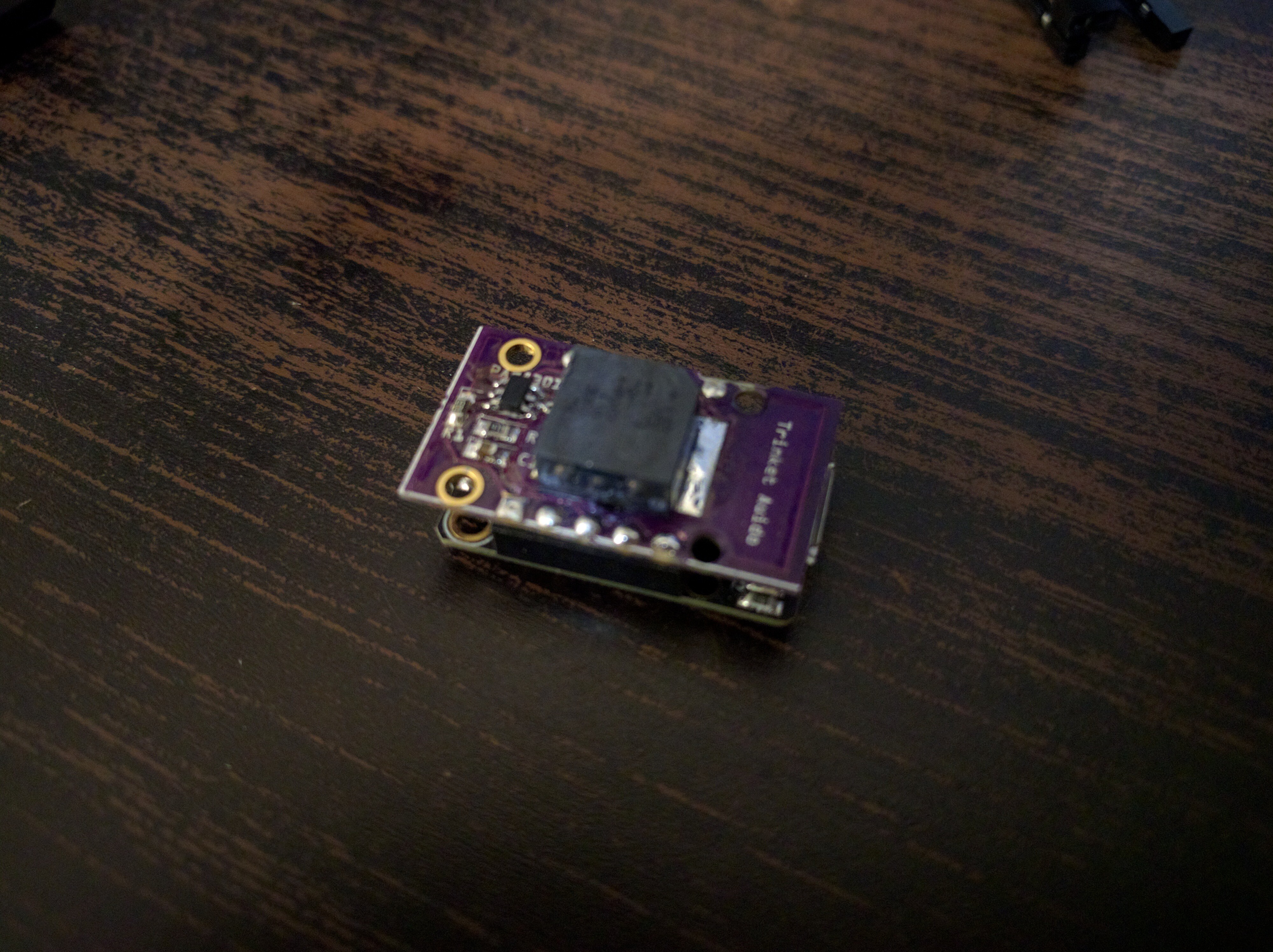
Audio Shield Done
10/17/2017 at 20:44 • 3 commentsAfter the problems I described in my last log, I added the PAM8301 chips to the order at Mouser that I was making. I got the chips yesterday, but didn't really have time to try anything. Today I finally replaced the Chinese chip with the one from Mouser, and lo and behold — it works! Well, I also got better speakers in the same order, and I also replaced that. They are quite loud!
![]()
By the way, if you want to use CircuitPython with that shield, you have to compile your own — the default doesn't have the audioio module included, due to space restrictions. But if you remove some other module you are not using (like the analogio in my case), it will fit.
Now I only have one shield left to get to work — it's assembled and the I²C address enumerates, but I need to write a driver for CircuitPython for it.
Update: there was still one trivial problem left with the audio shield — the mirrored footprint for the amplifier chip. So if you don't want to solder yours up-side-down, Like I did, then better use the corrected PCB available here: https://oshpark.com/projects/OatupN72
-
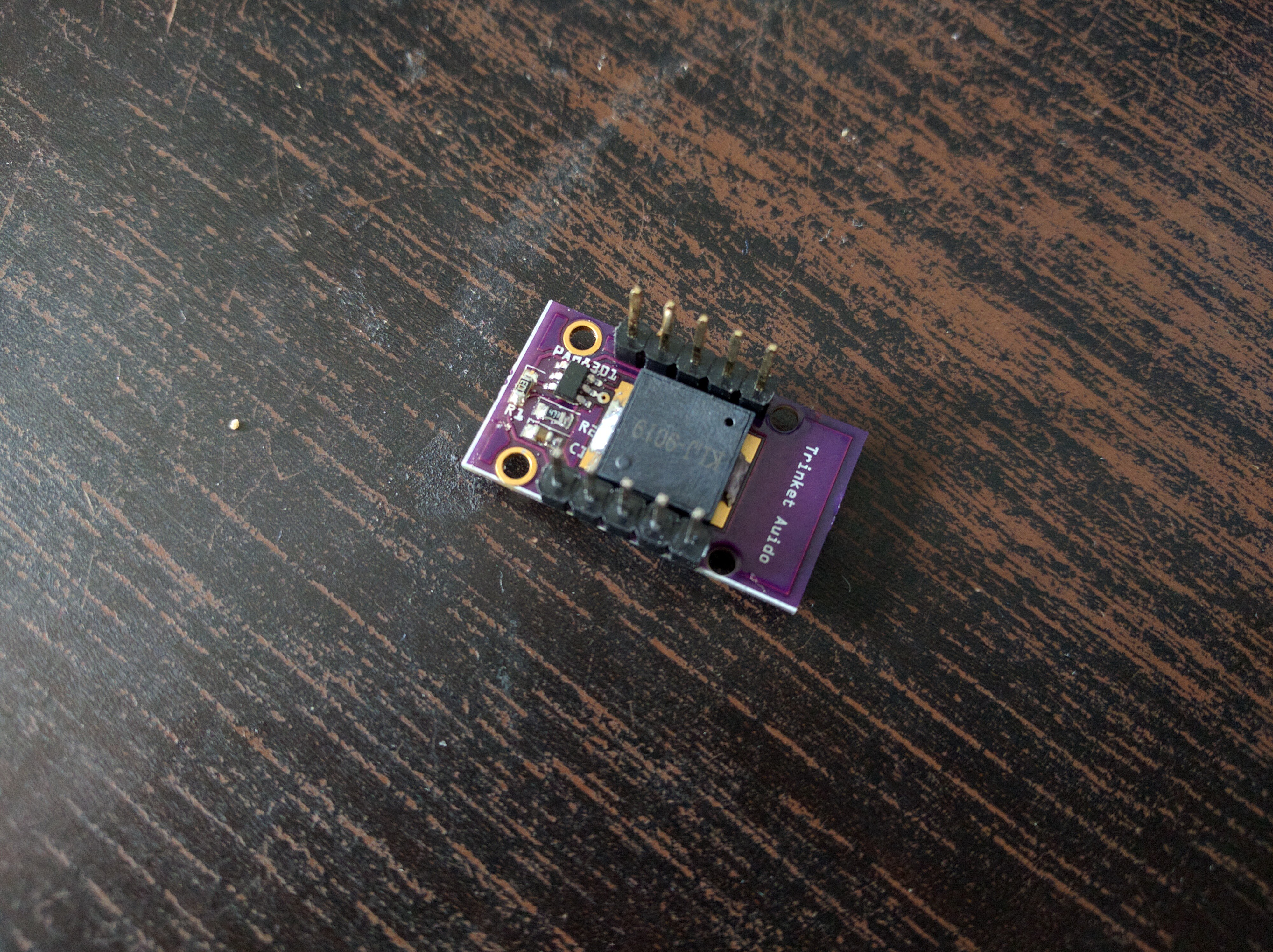
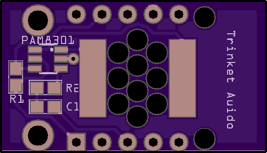
Why I Hate Analog Circuits
10/10/2017 at 17:40 • 6 commentsI'm completely hopeless with analog circuits. I think part of it might actually be a self-fulfilling prophecy — I know that I'm bad at it, so I'm not even trying. Usually I just try and copy any analog pieces I need from other projects, cargo-culting them and hoping they will work. A case in point: the audio shield.
![]()
Simplicity itself. A small audio amplifier, connected through a resistor and capacitor to the DAC pin on one side, and to an SMD speaker on the other. What could possibly go wrong?
First of all, I re-used a footprint for the PAM8301 amplifier, using a part for some sparkfun's DAC chip. It's exactly the same size, I just changed the labels on the pins. What I failed to note is that the pins on that chip are numbered in the opposite direction than on my amplifier. So to start with, I had to bend the pins of the chip the other way and dead-bug it. Fine.
Next thing I am a little less sure of. I mean, I am sure it doesn't work, but I'm not sure why. If I connect a piezo to the DAC pin directly, I get the sound that I'm playing (although very quietly). If I use the amplifier (with a 47kΩ resistor and 0.1µF capacitor between the pin and the input of the amp), I get nothing. And it gets warm. Sounds like it's simply connected wrong, but I verified the PCB and the datasheet a million times already.
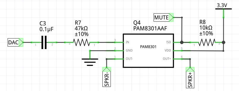
I must be missing something obvious, here's the schematic so that you can laugh at my ignorance:
![]()
Oh, and yes, I copied it. From Adafruit's Circuit Playground Express board, which also uses a SAMD21 chip and a very similiar SMD speaker.
-
The Only Shield You will Ever Need
10/10/2017 at 09:49 • 0 commentsToday a column of purple trucks arrived in front of my house, and dumped three containers of PCBs from @oshpark...
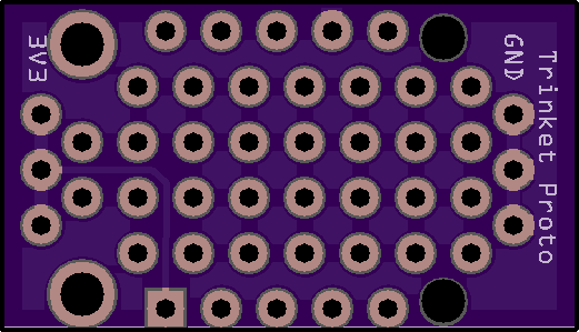
Well, not really, but there were no less than three envelopes in my mailbox. So I can finally assemble some of the shields. Spoiler: the proto shield is the only one that works, and only because it has no components.
Assembled proto shield:
![]()
Impressive, eh? But to tell the truth, it will be super useful for the small trinket-based projects.
-
Pretty Pictures
10/01/2017 at 22:16 • 2 commentsI realized that all I have been showing on the TFT shield screen are some random pixels — that doesn't really prove that it works correctly, does it? So I made a quick demo, displaying the CircuitPython's mascot, Blinka:
![]()
And the code:
import board import digitalio import busio from adafruit_rgb_display import st7735 dc = digitalio.DigitalInOut(board.D0) cs = digitalio.DigitalInOut(board.D1) spi = busio.SPI(clock=board.SCK, MOSI=board.MOSI) d = st7735.ST7735R(spi, cs=cs, dc=dc) d.fill(0) with open("blinka.raw", "rb") as f: for y in range(80): buf = f.read(320) d._block(y + 24, 0, y + 24, 159, buf) -
Buttons Shield
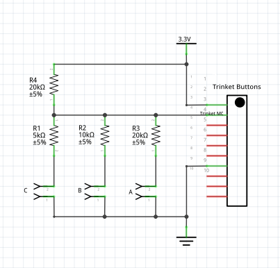
09/25/2017 at 21:34 • 0 commentsWith the nice small display, it would be nice to also have some buttons, so that you could at least navigate a menu. So I decided to make a shield with three buttons. The problem is, we only have one free pin left with the display shield on. I didn't want to muck with reusing the SPI pins for other functions while the CS pin is high, and other trickery, but I noticed that the free pin is an analog pin. Great, we can do the resistor ladder trick!
Basically, we will need a voltage divider, with different ratio of resistors switched by different buttons. Something like this:
![]()
When no button is pressed, the analog pin is pulled up to 3.3V with the 20kΩ resistor, and the analog pin reads its maxium value. When button A is pressed, half of that voltage is redirected to ground, and the analog pin only reads 1.65V. When B is pressed, ⅓ of the voltage is redirected, and the pin should read 2.2V. When both A and B are pressed, ⅗ of voltage gets redirected, and the pin reads 1.32V. And so on, adding button C for ⅕.
Now, looking at the voltage we can figure out exactly what combination of buttons has been pressed. It gets even easier if you only look at the top 3 bits of the reading.
The shield itself is designed to go on the bottom of the trinket — because the display goes on top, of course.
![]()
-
More Shields
09/24/2017 at 20:24 • 0 commentsYou might have noticed from the previous log that there is a LED shield and a buttons shield in the works. In fact, I already have the PCB for the buttons shield, I just need to figure out what resistors to use for it. I'm still waiting for the PCB for the LED shield.
Today I designed two more: an audio shield, with a small amplifier and a speaker, connected to the DAC pin of the Trinket M0, and a prototyping shield, which is just an empty PCB with a lot of empty holes — for quick-and-dirty shields as you need them. I will write about them more when I get them to work.
![]()
![]()
-
Repository and License
09/22/2017 at 09:21 • 2 commentsI have put all the shields I made so far in one repository at https://bitbucket.org/thesheep/trinket/src and also added a license, the usual CC BY-SA. You will need to install Fritzing to open the files and generate gerbers from them.
There also @oshpark links, so that you can order the PCBs from them:
- Trinket TFT
- Trinket PWM (untested)
- Trinket LED (untested)
- Trinket Buttons
-
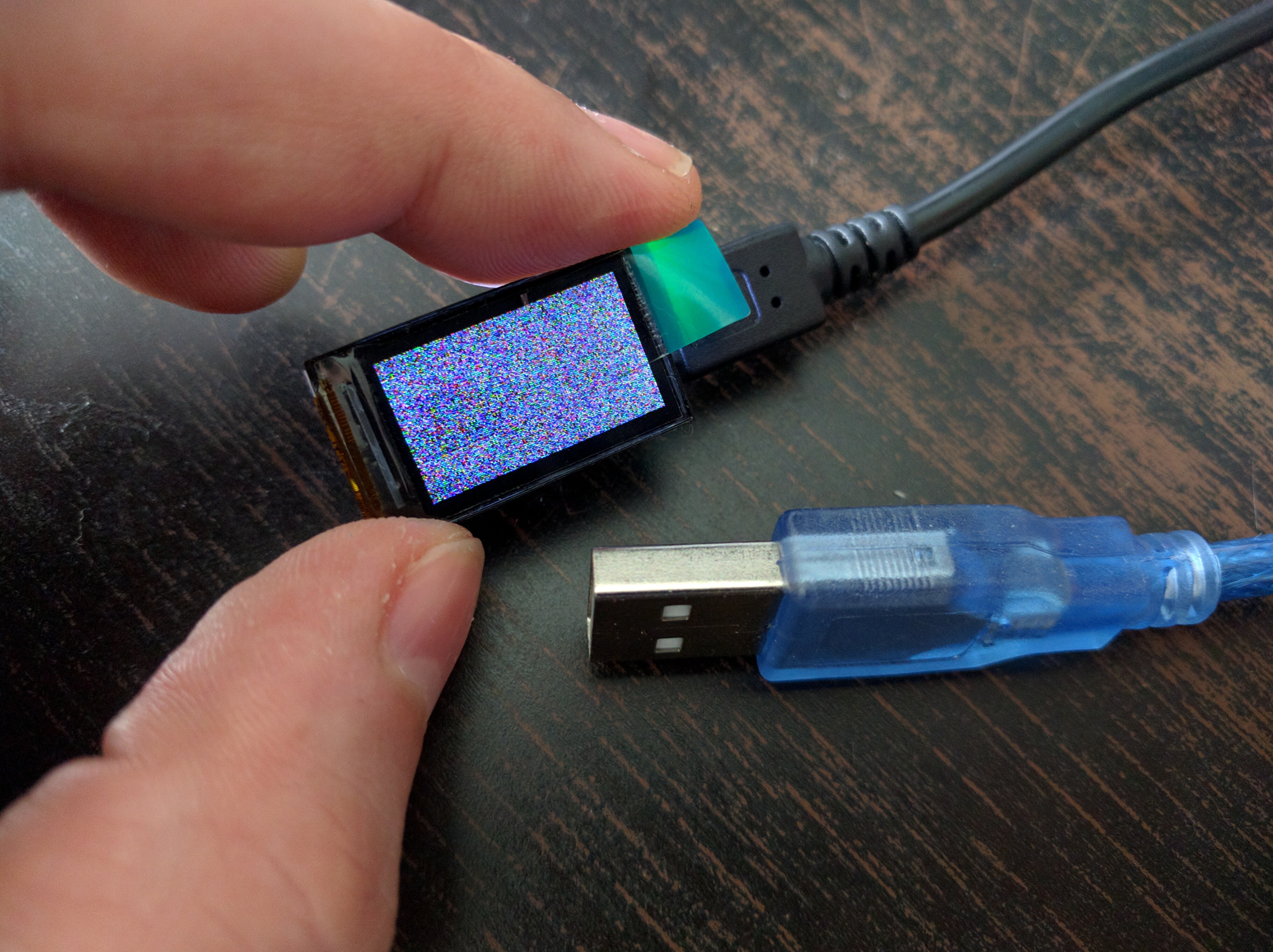
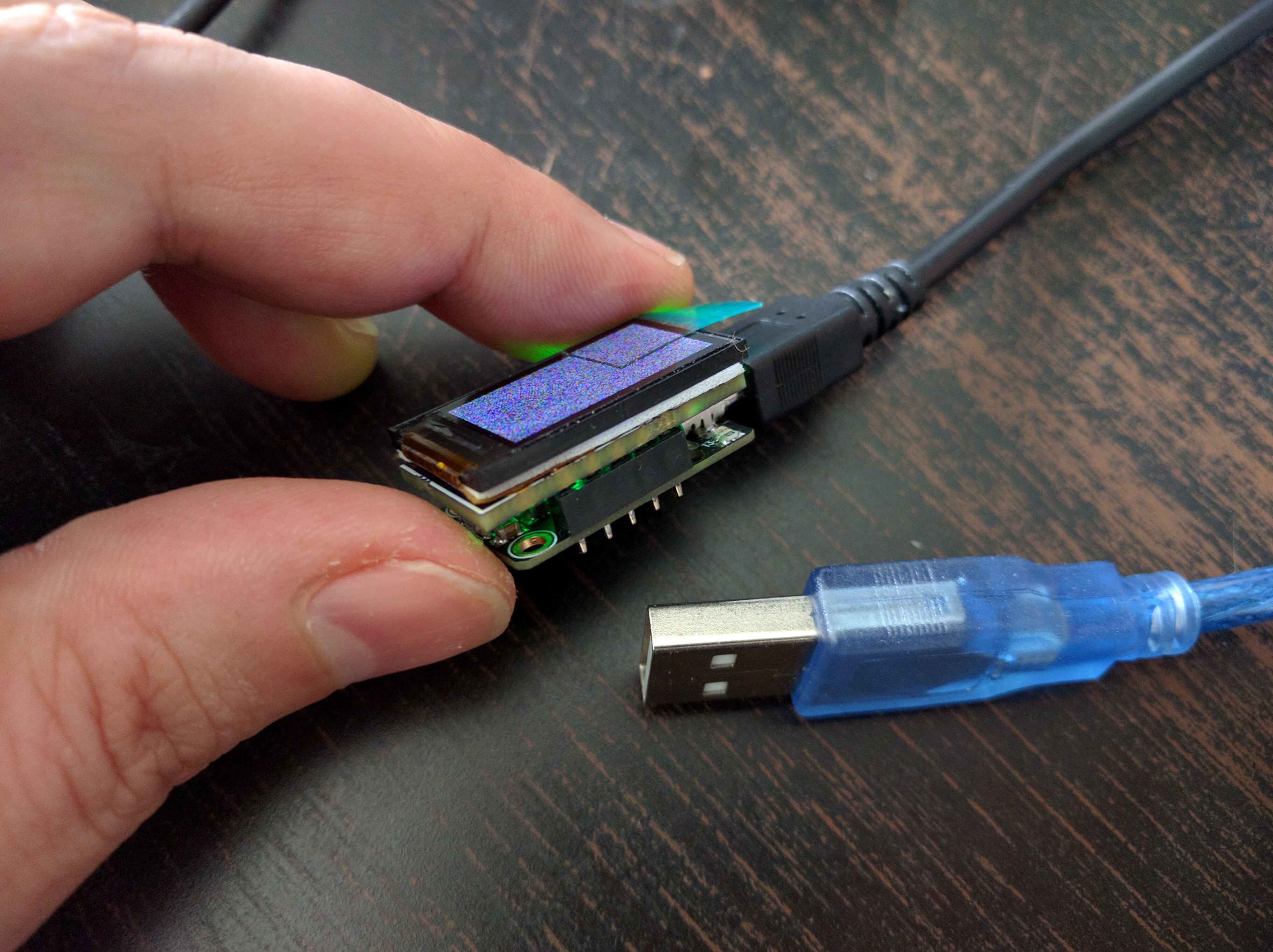
Trinket M0 TFT Finished
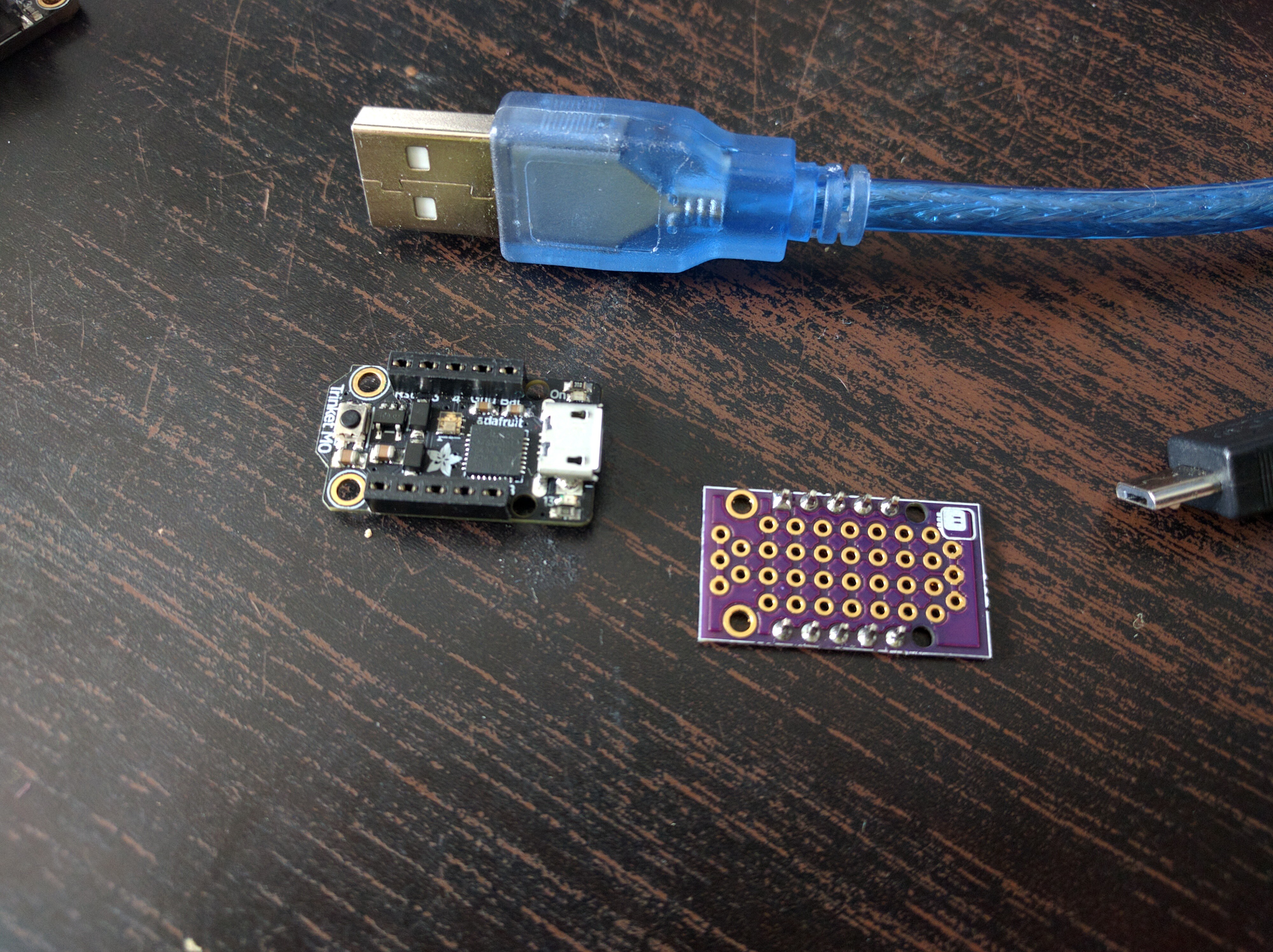
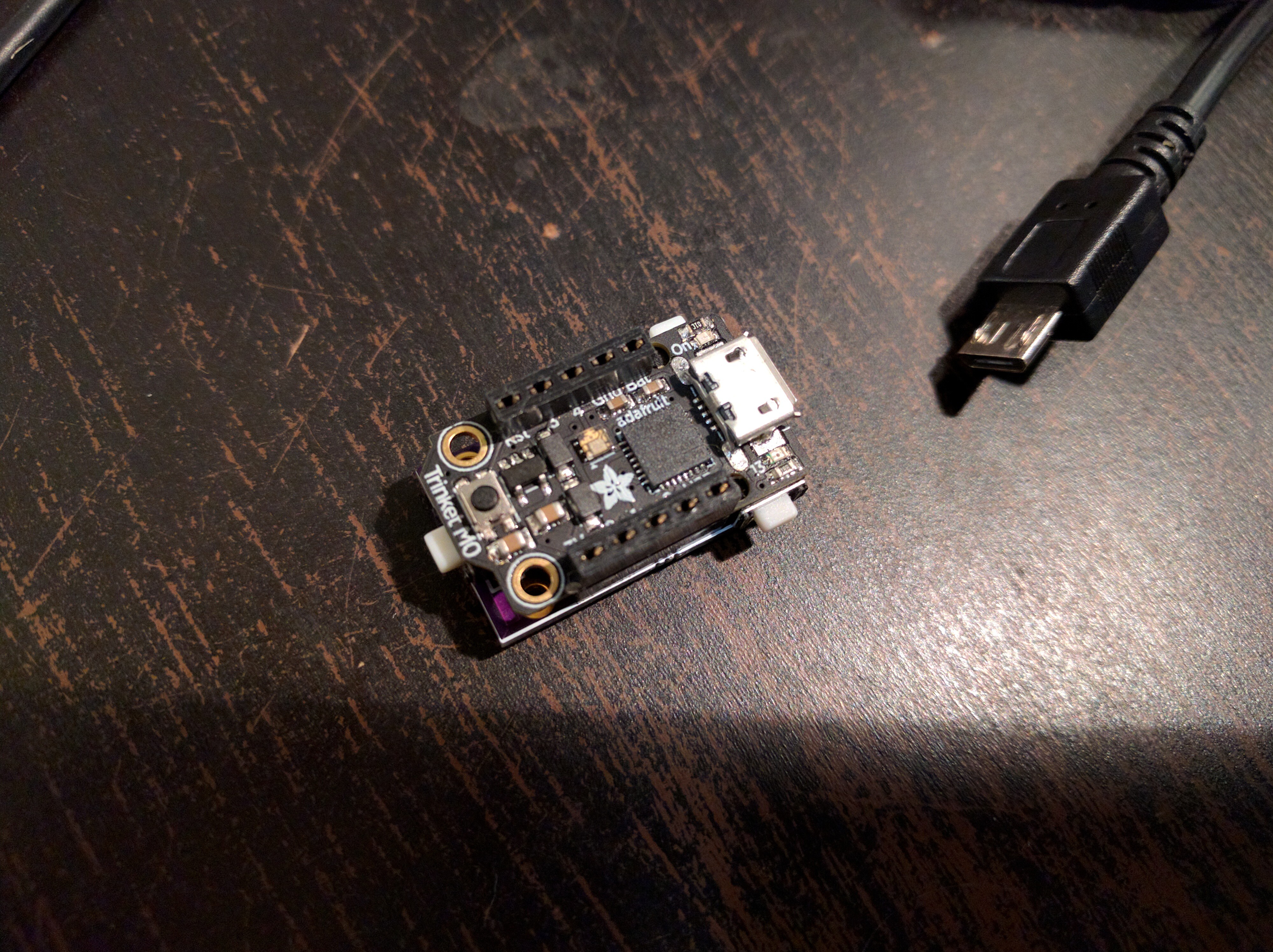
09/22/2017 at 09:12 • 0 commentsThe most recent version of the PCB for the Trinket M0 TFT shield arrived, and I assembled and tested it. This one works perfectly. As they say, fourth time is the charm. Here it is with a USB plug for scale:
![]()
![]()
-
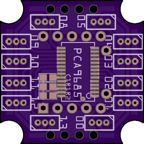
Trinket PWM Shield
09/19/2017 at 21:40 • 0 commentsThis is the standard thing for controlling servos, which I already made for D1 Mini and for OpenMV. Now it's time for the same thing for the Trinket. Except there isn't that much space there, so I'm going to do it with 1.27mm servo plugs (good for some of the sub-micro servos). Shortly after I ordered the PCBs I realized that I swapped the SDA and SCL lines again. So I made a fixed design, but this time I spaced the servo sockets a bit, to make sure I can use those pico-blade sockets for them, and made the whole thing into a robot base – 1×1 inch.
![]()
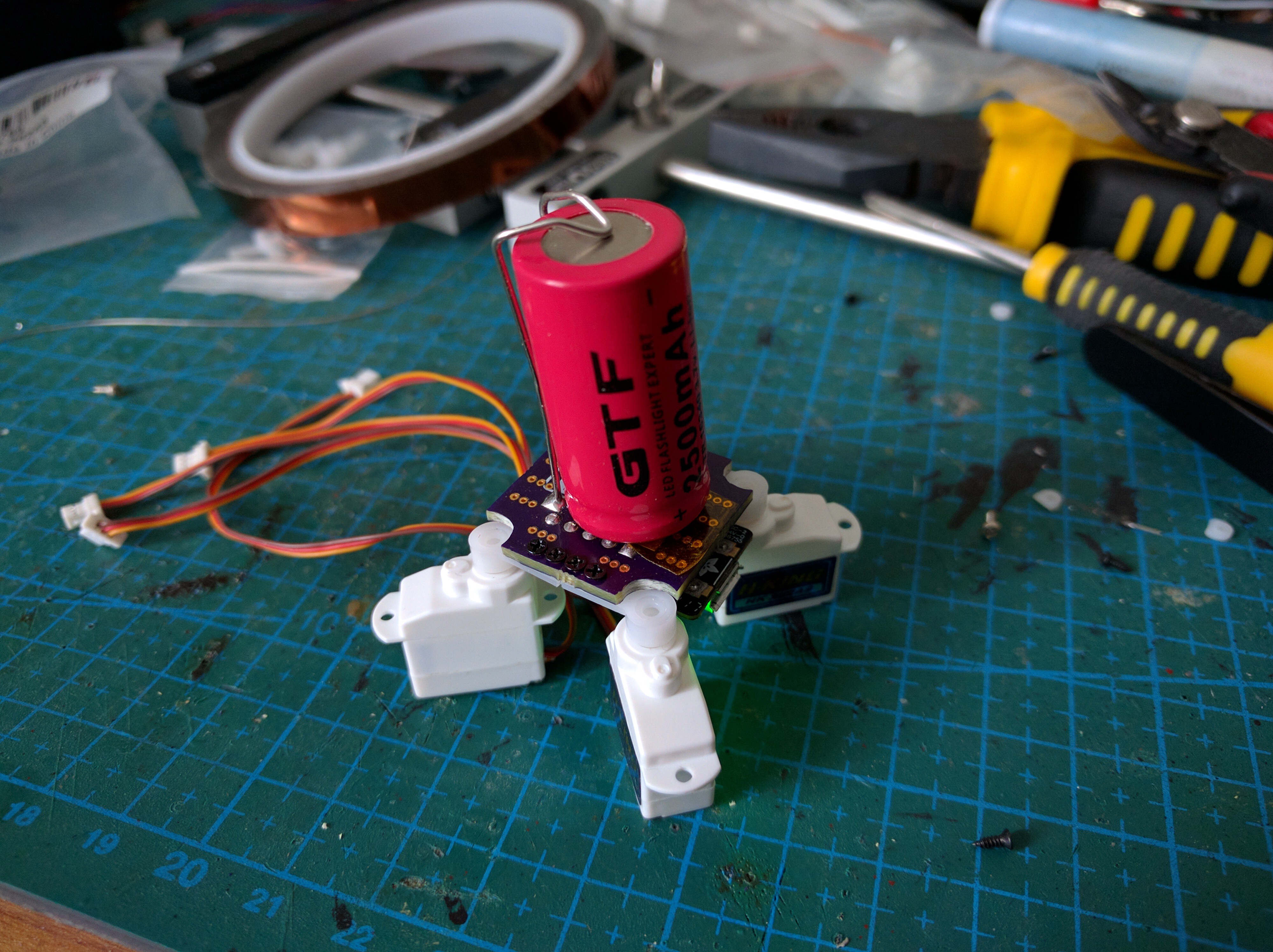
This came today, and I assembled two boards. One is for the #Pony Bot, and there will be a separate update for it, and the second is for a new spider robot that I'm considering:
![]()
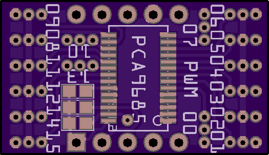
I am not sure yet how it will look or whether I will keep this battery on top — probably not. Anyways, once that's done, I decided to redo the PWM shield in the small version, but try to fit all 16 outputs.
![]()
It's a little bit tight, but should work. I could even probably fit the address-selection jumpers on the back, but decided against it. 16 servos should be enough for a small Trinket.
By the way, the servos for that robot? Turns out that HobbyKing changed their connectors, they now use a JST 1.0 instead of a pico-blade. Which have 1mm pitch, not 1.27mm. Sigh.