Close
0%
0%

Compact accelerometer for experiments

This device is a battery powered, usb connectable accelerometer with onboard memory, planned for experimental use in basic physics lessons

vayVay
Similar projects worth following
The project came into being as the plan to visualize the acceleration on for example pendulums or toy cars into 3 axis for use in physics lessons in our mechanical engineering study course. After 3 iterations this version came into life, mostly made out of parts laying around.

It consists of the hardware, a lipo cell + electronics, the sensor, an atmega with ram module and an usb to uart interface.
The software is a combination of the avr code and a windows gui made with C#.
Since it uses a virtual com-port, no drivers are needed.

The accelerometer got a fixed measurement frequency of 1kHz (1 datapoint every 1ms).
The measurement range can be set between +-2,4 or 8g with a 11bit resolution.
The onboard memory got enough space for a measurement cycle of around 12 seconds.

Right now these modules are used in the first semesters of our mechanical engineering bachelor courses. It also has been used for measurements in several bachelor projects at our university.

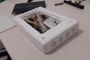
The device is designed to be as small and lightweight as possible. This also allows this module to be mounted on a wide variety of different stuff for measurements.

Using the device:

Turn on the switch (button should be on the "outside"). The device is now active.

When pushing the red button, the LED shines and a measurement cycle begins. The device will now save a measurement point every 1ms until the storage is full (after about 12sec) or the button is pressed again. A measurement cycle is finished, when the LED turnes off.
Keep the device turned on. Turning it off will delete the saved measurement.
Pushing the button again will start a new cycle and overrides all existing data.

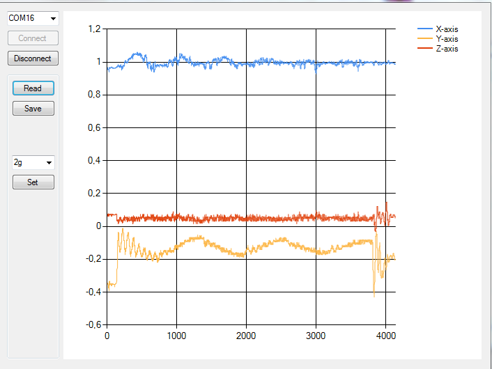
Connect the device via micro USB (every phone charging cable can be used) to your pc and start the GUI. Select the COM-port of the device (most likely something above com3) and klick connect. The data of the last measurement can now be read out and visualized by klicking the "read" button, and be saved in an .txt file with the savebutton for further investigation/calculation in matlab.

Here is an example of how is may look like on a pendulum:


The device can stay plugged in for further emasurements and will always charge up when connected.

The Battery is automatically charged whenever the device is plugged into the USB port.
USB_V3.dwg

DWG Drawing - 174.26 kB - 09/12/2017 at 11:53

Download

avr_sw.zip

V1.0

Zip Archive - 3.13 kB - 09/12/2017 at 11:52

Download

GUI.zip

V1.0, Windows executable

Zip Archive - 10.89 kB - 09/12/2017 at 11:51

Download

USB_V3.sch

softgrid-sch - 365.49 kB - 09/12/2017 at 11:50

Download

USB_V3.brd

brd - 120.99 kB - 09/12/2017 at 11:49

Download

  • The GUI

    Vay09/12/2017 at 12:28 0 comments

    Very basic GUI:


    The user can connect to the device using the GUI. When connected, the measurement data can be read out, visualized, and saved for later use. Also the measuring range of the accelerometer can be set between +-2,4 or 8g

  • The case

    Vay09/12/2017 at 12:20 0 comments

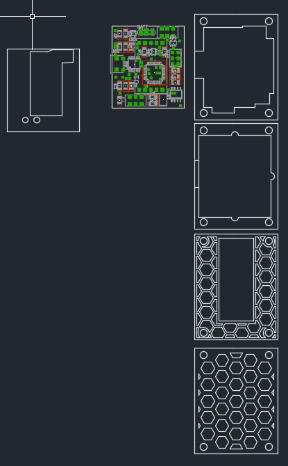
    The case is made out of 4 layers of 3mm acrylic, a small sheet of 1,2mm plastic to hold the pcb in place and 4 3mm vinyl screws and bolts. The bottom layers got some cutouts to make room for the lipo cell and to safe weight. Everything is drawn in Autocad and cut out with an lasercutter.


  • The PCB-design

    Vay09/12/2017 at 12:14 0 comments

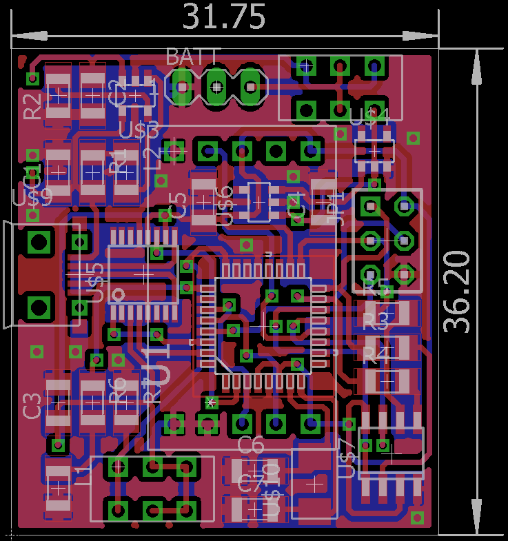
    The design was meant to be as compact as possible. As well as being able to be soldered by hand.
  • Rest of the circuit

    Vay09/12/2017 at 12:11 0 comments

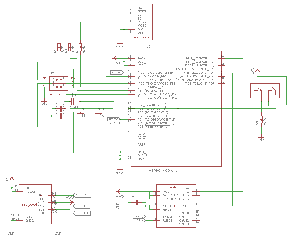
    The rest of the circuitry:


    This shows the Atmega as the main processor with basic ISP setup and an 16MHz quarz. As well with a button and an led as an "user interface". The peripherals are connected over the bus interfaces.
    accelerometer -> i2c
    ram module -> SPI
    usb interface -> UART

  • The LiPo circuit

    Vay09/12/2017 at 12:06 0 comments

    The first circuit is the power source.


    The 3,3V for the device is delivered by an mcp5504-3 LDO voltage regulator. This regulator is chosen, because it got an enable input. This input is fed by the NCP300 chip, who gives out an high signal, as long the cell-voltage is above 3,2V. This protects the cell from deep discharge and ensures the voltage is always high enough for the circuit.

    The MCP73831 is a programmable (via R2) lipo charging IC used for safe charging of the cell via the micro-USB port.

    The little bridge on the switch is because the cell can be used and charged simuntaniously.

View all 5 project logs

Enjoy this project?

Share

Discussions

Electromake.pl wrote 09/28/2018 at 00:27 point

Hey,

First of all, it’s a just awesome project :D BUT ….  I found more compact  and simpler one here:  https://www.tindie.com/products/11072/

It good If you don’t want to bother soldering any electronics and want SIMPLE PLUG&PLAY like Arduino device.

  Are you sure? yes | no

Vay wrote 11/02/2018 at 10:47 point

Thanks for the hint. I will definitly look towards this when we need new devices.
The only downside i see here, is that it got no battery and needs to stay plugged in. Our devices are used on stuff like slotcars so .... maybe there is a workaround

Thanks !

  Are you sure? yes | no

Similar Projects

Does this project spark your interest?

Become a member to follow this project and never miss any updates