-
The GUI
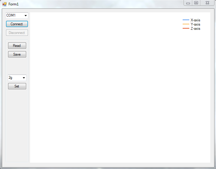
09/12/2017 at 12:28 • 0 commentsVery basic GUI:
The user can connect to the device using the GUI. When connected, the measurement data can be read out, visualized, and saved for later use. Also the measuring range of the accelerometer can be set between +-2,4 or 8g
-
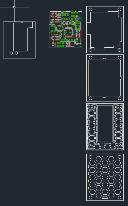
The case
09/12/2017 at 12:20 • 0 commentsThe case is made out of 4 layers of 3mm acrylic, a small sheet of 1,2mm plastic to hold the pcb in place and 4 3mm vinyl screws and bolts. The bottom layers got some cutouts to make room for the lipo cell and to safe weight. Everything is drawn in Autocad and cut out with an lasercutter.
-
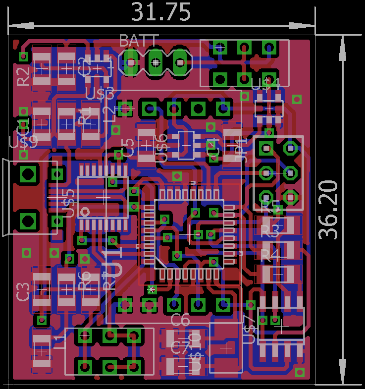
The PCB-design
09/12/2017 at 12:14 • 0 comments![]() The design was meant to be as compact as possible. As well as being able to be soldered by hand.
The design was meant to be as compact as possible. As well as being able to be soldered by hand. -
Rest of the circuit
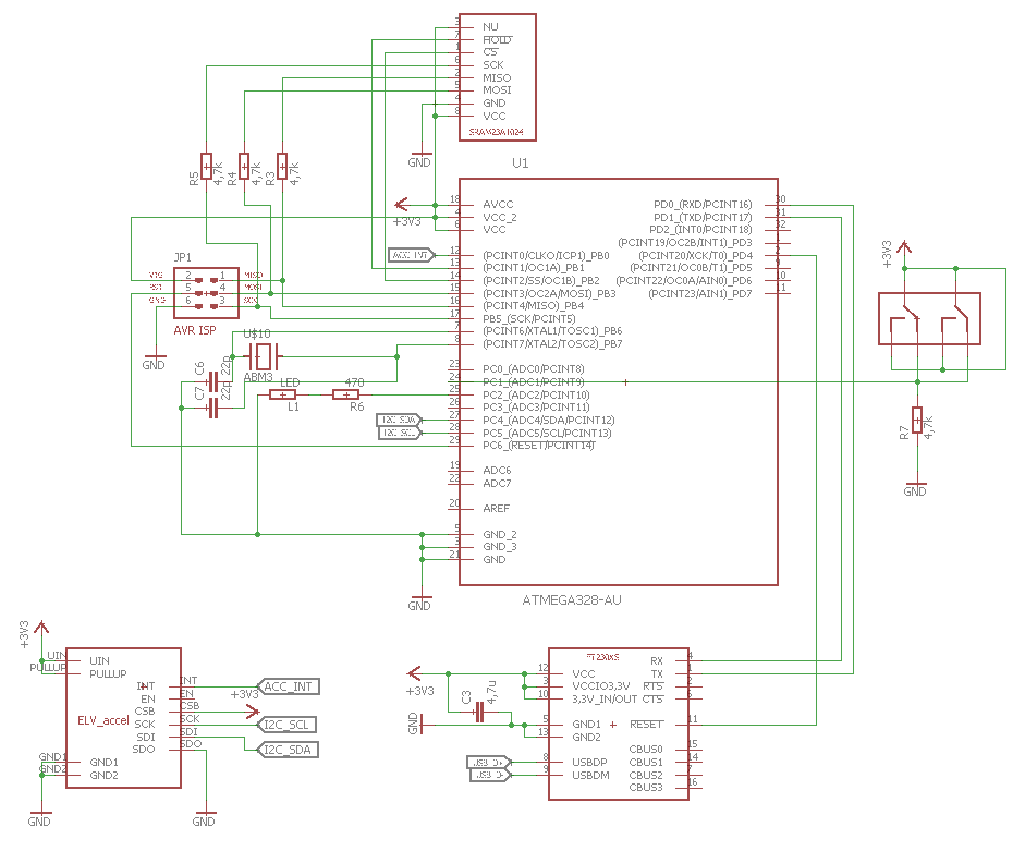
09/12/2017 at 12:11 • 0 commentsThe rest of the circuitry:
![]()
This shows the Atmega as the main processor with basic ISP setup and an 16MHz quarz. As well with a button and an led as an "user interface". The peripherals are connected over the bus interfaces.
accelerometer -> i2c
ram module -> SPI
usb interface -> UART -
The LiPo circuit
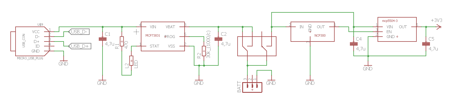
09/12/2017 at 12:06 • 0 commentsThe first circuit is the power source.
![]()
The 3,3V for the device is delivered by an mcp5504-3 LDO voltage regulator. This regulator is chosen, because it got an enable input. This input is fed by the NCP300 chip, who gives out an high signal, as long the cell-voltage is above 3,2V. This protects the cell from deep discharge and ensures the voltage is always high enough for the circuit.
The MCP73831 is a programmable (via R2) lipo charging IC used for safe charging of the cell via the micro-USB port.
The little bridge on the switch is because the cell can be used and charged simuntaniously.
Compact accelerometer for experiments
This device is a battery powered, usb connectable accelerometer with onboard memory, planned for experimental use in basic physics lessons
 The design was meant to be as compact as possible. As well as being able to be soldered by hand.