 Yann Guidon / YGDES
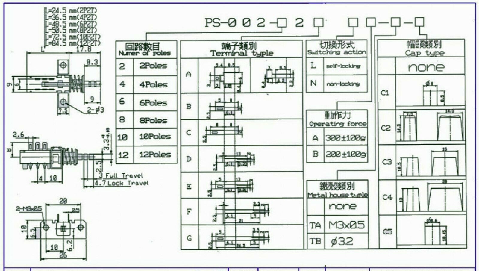
I have received and tested all the interlocked switches :-)
and I'm updating the layout and dimensions, using the diagrams I have found on the web:
So far the layout of the panel is:
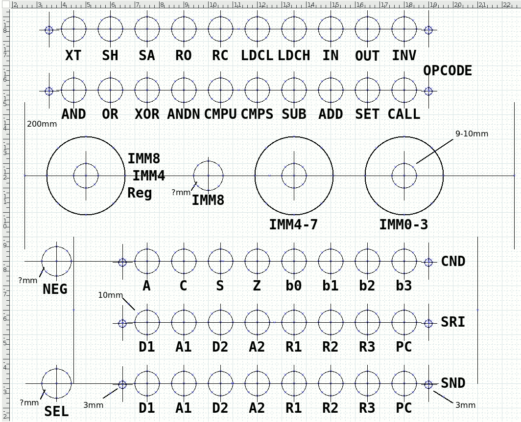
but many questions are still in the air...
I can print with my laser printer to the exact scale so this will be very useful: no need of a CNC ! but it only moves the problem around.
How can I transfer the toner to the front panel (aluminium) for the labels of the buttons ?
I added the "SEL" button : it's a SPDT switch that selects which circuit gets the power/signal, either the assembler panel or the program ROM. That makes now 3 switches (IMM8, NEG and SEL) and I haven't decided/found which model to use. I need a low-force, high-endurance switch with a long lever (10mm or 12mm ?) so the drill diameter is undetermined (until I find THE model that fits).
The SEL button changes several things, because initially I wanted to use a 16-pole dual throw switch to select the value sent to the instruction decoder. The operating force and endurance would not be satisfying because I want to alternate between both sources easily and fast. Now the instruction bus is shared between the ASM panel, the instruction ROM and the eventual electronic/remote interface.
For the YGREC16 with 24 instruction bits, I started with positive logic, then realised it would be more complex for the driving electronics so I changed to a different driving system where PNP transistors just pull the signal to 0V. But overall this is not easy to manage and a return to "positive logic" seems unavoidable.
Another consequence is that the outputs of the asm panel must be "diode protected" because some signals can be shorted by the switches. This is not a problem when the panel is operated alone but it will interfere in some cases with the ROM and the external interface. Another version of the diagram is necessary... So here it is!
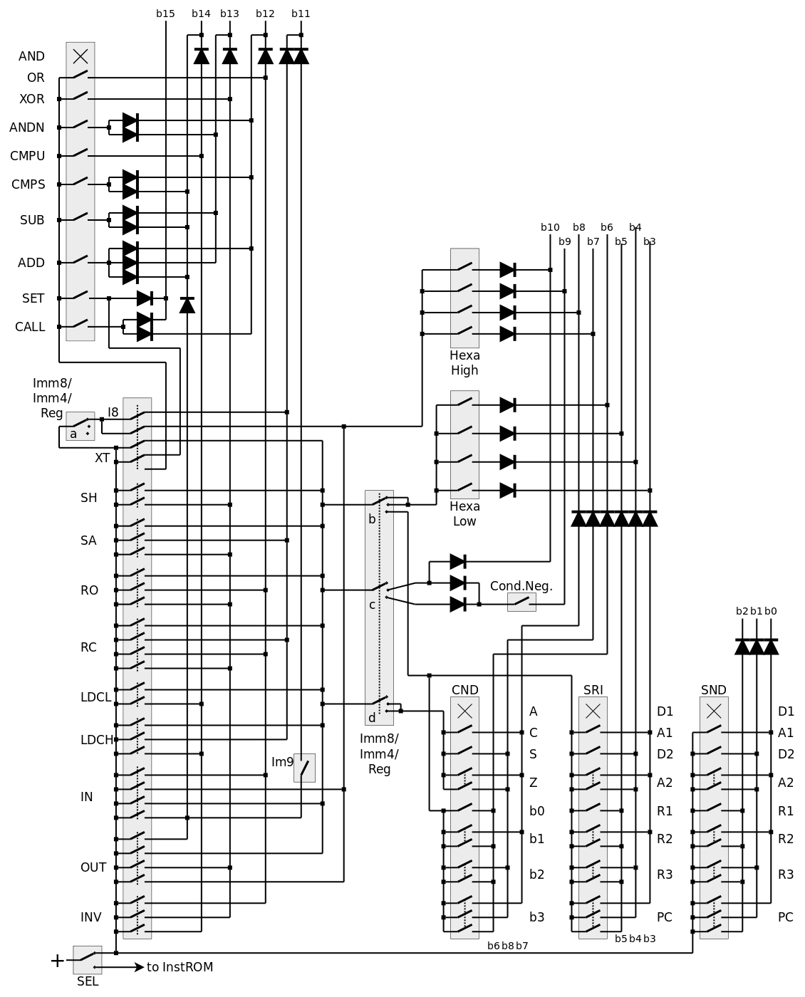
There are now 38 diodes now. It is not a tragic increase but there is a good side effect : all the signal paths have one diode drop, everything is now balanced !
Discussions
Become a Hackaday.io Member
Create an account to leave a comment. Already have an account? Log In.
I'll try PnP Blue :-)
Are you sure? yes | no
so, if you go that route, you could possibly etch the panel, too. Maybe if you printed in reversed colors, so the text was void of toner, you could etch the text into the panel, then fill the voids with paint of some sort.
Are you sure? yes | no
I was INDEED thinking about that as well :-D
Are you sure? yes | no
I have had luck with printing the text of panel labels reversed on overhead transparency sheets:
1) print the text reversed on the sheet, since the un-printed side of the sheet will be the panel face
2) spray-paint a background color (or colors) over the back of the sheet
3) gluing the sheet to the panel
4) cut the holes
I did it with multi-color printing and a gold flake spray paint on this clock:
https://cdn.hackaday.io/images/8805431463075881032.jpg
but here's a simpler example just using black printed text with a white spray:
https://cdn.hackaday.io/files/470302012131520/front-panel-example.jpg
note that the controls go to 11. It's the {white/pink/red} noise generator I use to get to sleep at night.
Are you sure? yes | no
oh, one more tip: washers are important on the controls to avoid the panel nuts from warping the sheet. You can see here where I didn't use the washers, the adhesive wasn't quite dry, and I warped the sheet a little around the holes. I also got thread-lock on the panel.
https://cdn.hackaday.io/images/1605261465096931986.jpg
Are you sure? yes | no
The problem might be the printing in reverse because my SW (dia) is quite lousy and won't do mirror/rotation...
I'll go for a "natural" colour, so a transparency sheet is a good idea, and I found spray glue, which I have to test... I hope it will not be ugly because i'd like to see the nice aluminium surface :-)
Are you sure? yes | no
you can save/export to PDF and mirror that before printing.
https://unix.stackexchange.com/questions/417026/tool-for-mirroring-pdf-file
BTW, I used Xfig for both of the above panels (!)
Are you sure? yes | no
Oh, I have tried gluing a clear sheet to aluminum. It does look ugly, and you can't get all the bubbles out. YMMV, though.
You could use metallic "silver" spray paint for the background color.
Are you sure? yes | no
I can't find export to PDF in dia... I see some vector formats : eps, dxf and svg
Are you sure? yes | no
if you install a PDF pseudo-printer, you can just print PDF to a file
Are you sure? yes | no
I did a direct toner transfer onto the underside of plexiglass using overhead transparency and it turns out okay. You have to be careful not too hot as the plexiglass might start to soften/deform.
Are you sure? yes | no
you can also do toner transfer directly to an aluminum panel like on this project
https://www.youtube.com/watch?v=78xdefAWV00
Are you sure? yes | no