 Yann Guidon / YGDES
Let's now talk about the physical interface to the TAP :-)
As already mentioned, this TAP is designed to
- interface directly to a SPI master interface
- require as few pins as possible
- be as simple as possible so the host SW can do all the smart stuff
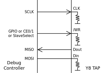
The typical application uses something like the Raspberry Pi and a half-duplex link with 3 signal wires :
- /WR input selects the data direction (0: write, 1 read from the core)
- Dat : multiplexed serial data in and out signal
- CLK input
The debug system could also access the /RESET pin but this should not be necessary.
/WR, CLK and Dat should have a weak pull-down resistor to prevent any spurious activity when the debugger is not connected.
However the state at these pins could be sampled by the Y8 during Power-On Reset (P.O.R.) to control the state when /RESET is released.
- /WR should not be high on its own because any unsuspecting device connected to the Dat pin could also be a driver and result in a "driver conflict". Thus /WR high would mean a debugger is actively connected and requesting to take over the pins.
- CLK is also usually low but the counter has "a condition" where the synchroniser oscillates during initialisation. Oscillations are removed when CLK is high at startup and it has no noticeable effect on the initialisation sequence.
- Dat should be weakly pulled to 0 because you never know what state would be output when /WR goes high, and a string of 0s is/will be a command for internal TAP reset.
The TAP interface could be implemented in a familiar 4-wires way, as a traditional SPI slave :
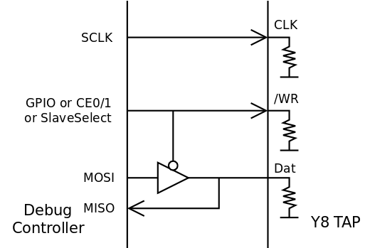
But since Din and Dout are not active simultaneously, a little tristate buffer circuit can save one pin on the TAP's side :
Ideally, with a microcontroller for example, the /WR signal is driven by a GPIO pin. However the Raspberry Pi has "some latency" (around one microsecond in some cases) which could be saved with another trick : use both SPI slave select pins, yet use only one CE pin. This also helps when dealing with the proper polarity, since /WR is active on both levels but Slave Select is usually active low.
Multiple TAPs could be accessed with the same port because the interface requires both /WR and CLK to work. If one of them, or both, is disabled (with a demultiplexer, 74HC238 or 239 as in the example below), commands can not be interpreted.
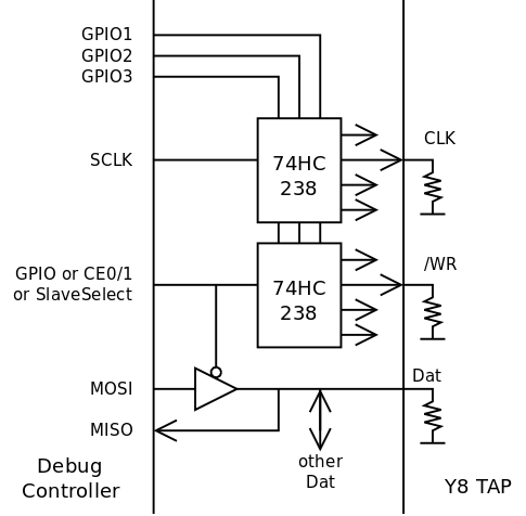
If /WR can go high for one TAP only, then the other TAPs will float their Dat pin, which implements the desired multiplexing. If CLK is not demultiplexed as in the above example, make sure to start all the new communications with a blank byte, which ensures that all the other TAPs will not interpret the data as valid commands.
Discussions
Become a Hackaday.io Member
Create an account to leave a comment. Already have an account? Log In.