txyz.info
-
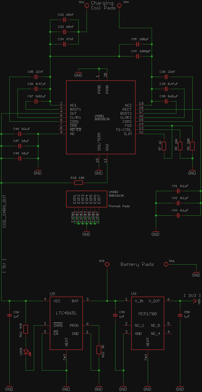
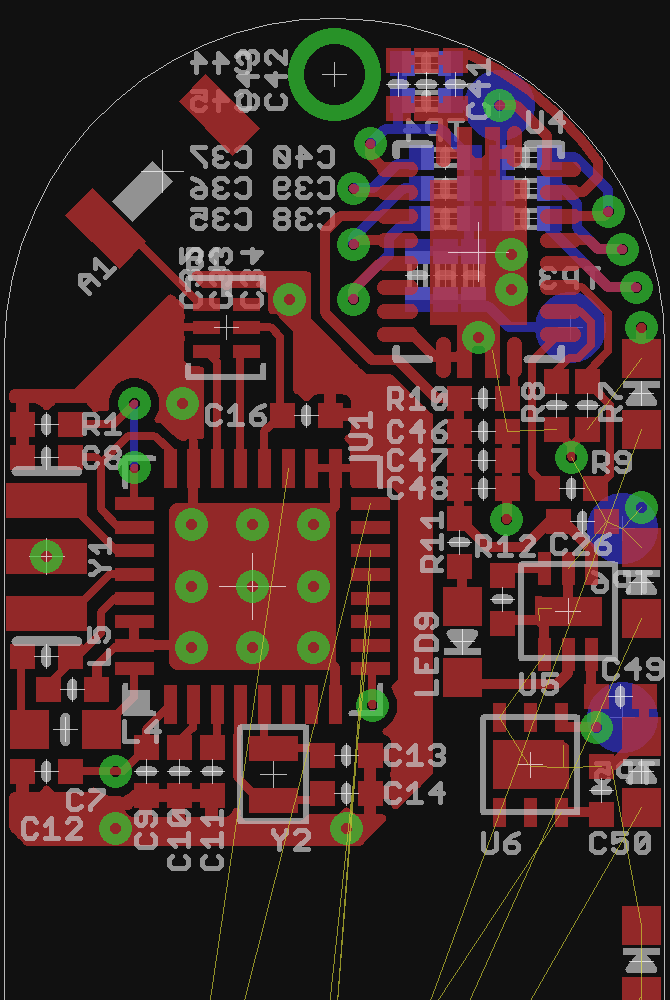
BQ51013B, LTC4065, MCP1700 Schematic and PCB layout completed.
02/23/2015 at 14:43 • 1 comment![]()
U4 BQ51013B - Wireless Power Receiver (for wireless charging). bq51013a.lbr
U5 LTC4065 - Complete Linear BatteryCharger in 2mm × 2mm DFN Package. LTC4065L.lbr
U6 MCP1700 - Linear Voltage Regulator with 1.6 µA Quiescent Current in 2mm × 2mm DFN Package. MCP1700.lbr
originally was MCP7331 in SOT23
originally was TLV70033 with 31 µA Quiescent Current in SOT23![]()
Latest Schematic and PCB layout you can find on GitHub.
Thank you for your support! I quit my day job to spend more time for B10N1C. -
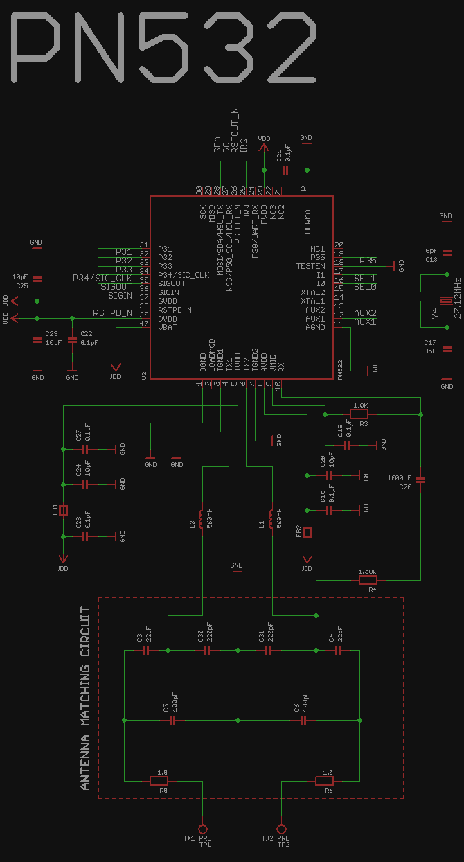
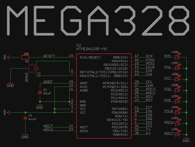
PN532 schematic and PCB layout completed. ATMEGA328, LED bar graph, EMG pads placed.
10/26/2014 at 01:55 • 0 comments![]()
![]()
![]()
RC522 replaced on PN532.
Y4 - 27.12MHz Crystal from Murata, Crystal-Murata-XRCGB27M120F3M00R0.lbr
Trace width 8mil, via drill 10mil & via diameter 20mil.
-
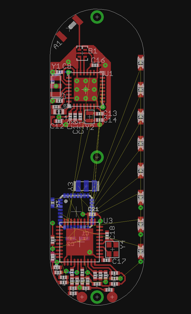
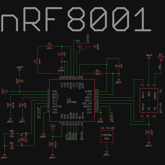
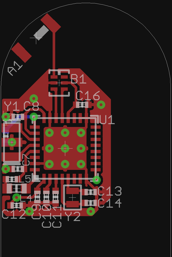
nRF8001 schematic and PCB layout completed
10/13/2014 at 19:00 • 0 comments![]()
![]()
Y1 - 16MHz Crystal with build in capacitors (the same like on Arduino Pro Mini), SparkFun-FreqCtrl.lbr
Y2 - Super tiny 32.768 kHz crystal, Crystal-ABS05-32.768KHZ-9-T.lbr
0402 package size for all resistor and capacitors
-
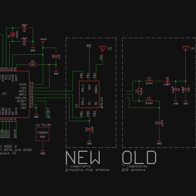
Improvement for NRF8001 circuit
10/12/2014 at 02:51 • 0 comments![]()
Johanson 2450BM14A0002 balun (U2) + Johanson 2450AT18A100 chip antenna (U3) = smaller PCB area for NRF8001 circuit & smaller BOM.
BALUN with NRF8001 reference schematic
Johanson 2450BM14A0002 balun Eagle library
Johanson 2450AT18A100 chip antenna Eagle library
-
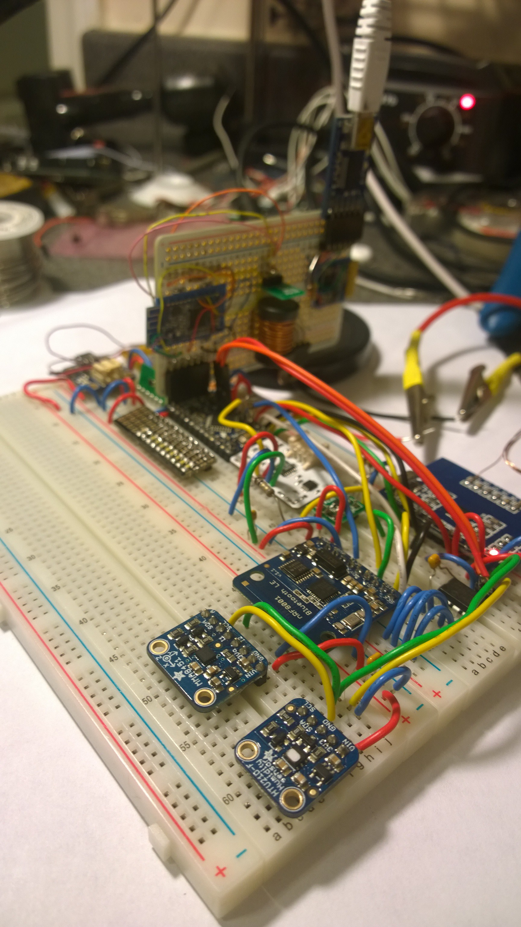
Done with breadboard prototyping
09/29/2014 at 03:39 • 3 commentsLast 3 electronic components was tested with whole system.
HTU21D - humidity and high precision temperature sensor in one IC
MMA8451 - Triple-Axis Accelerometer w/ 14-bit ADC
nRF8001 - Bluetooth Low Energy IC with SPI interface
![]()
From tomorrow I'm starting PCB design in Eagle. I'm gonna keep you updated about PCB progress as well.
-
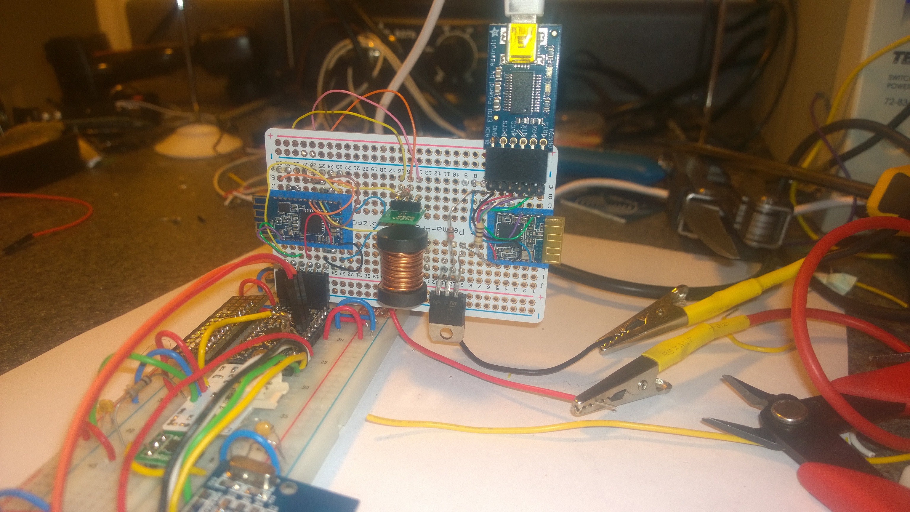
NEW Solution for Arduino Wireless Reset
09/29/2014 at 02:31 • 0 commentsI spent so much time trying to figure out how to wirelessly reset the Arduino, which is a requirement for uploading code to the processor.
I came up with a new solution for the wireless reset: On the programmer side, I have a powerful electromagnet connected through a power transistor to a RTS pin on a FTDI adapter. On B10N1C PCB I have a Hall effect sensor connected to a reset pin. HM 10/11 stays in design.
The electromagnet must be located close to the skin in order to accomplish the uploading code.
I have already a prototype for testing.
![]()
![]()
-
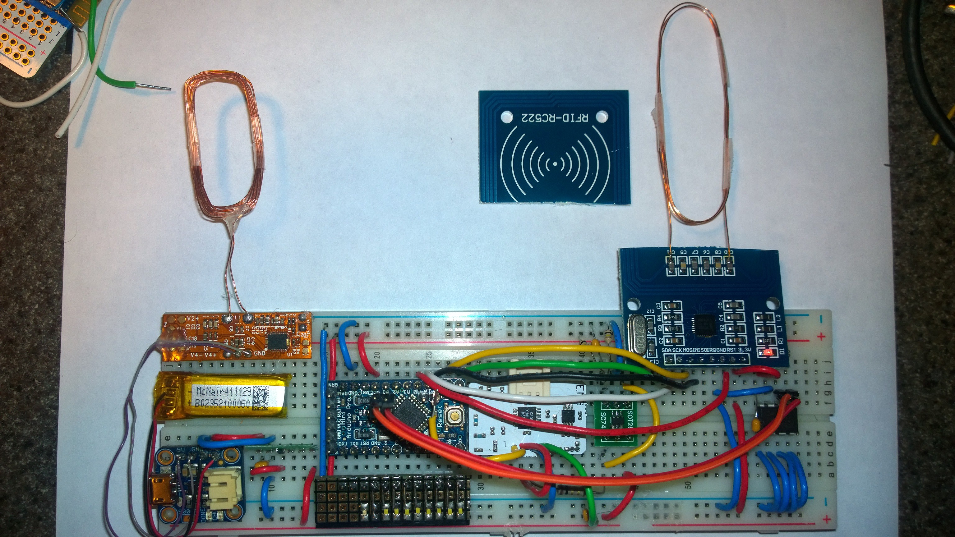
Saving RFID tag into i2c memory
09/29/2014 at 00:30 • 0 comments![]()
RFID Reader/writer IC: http://www.nxp.com/documents/data_sheet/MFRC522.pdf
Arduino code from my video: https://github.com/txyzinfo/B10N1C/tree/master/Arduino%20Code/RFID_to_memory_test
Сode depends on the library: https://github.com/miguelbalboa/rfid
-
Using EMG circuit as EMF sensor
09/28/2014 at 18:41 • 0 comments -
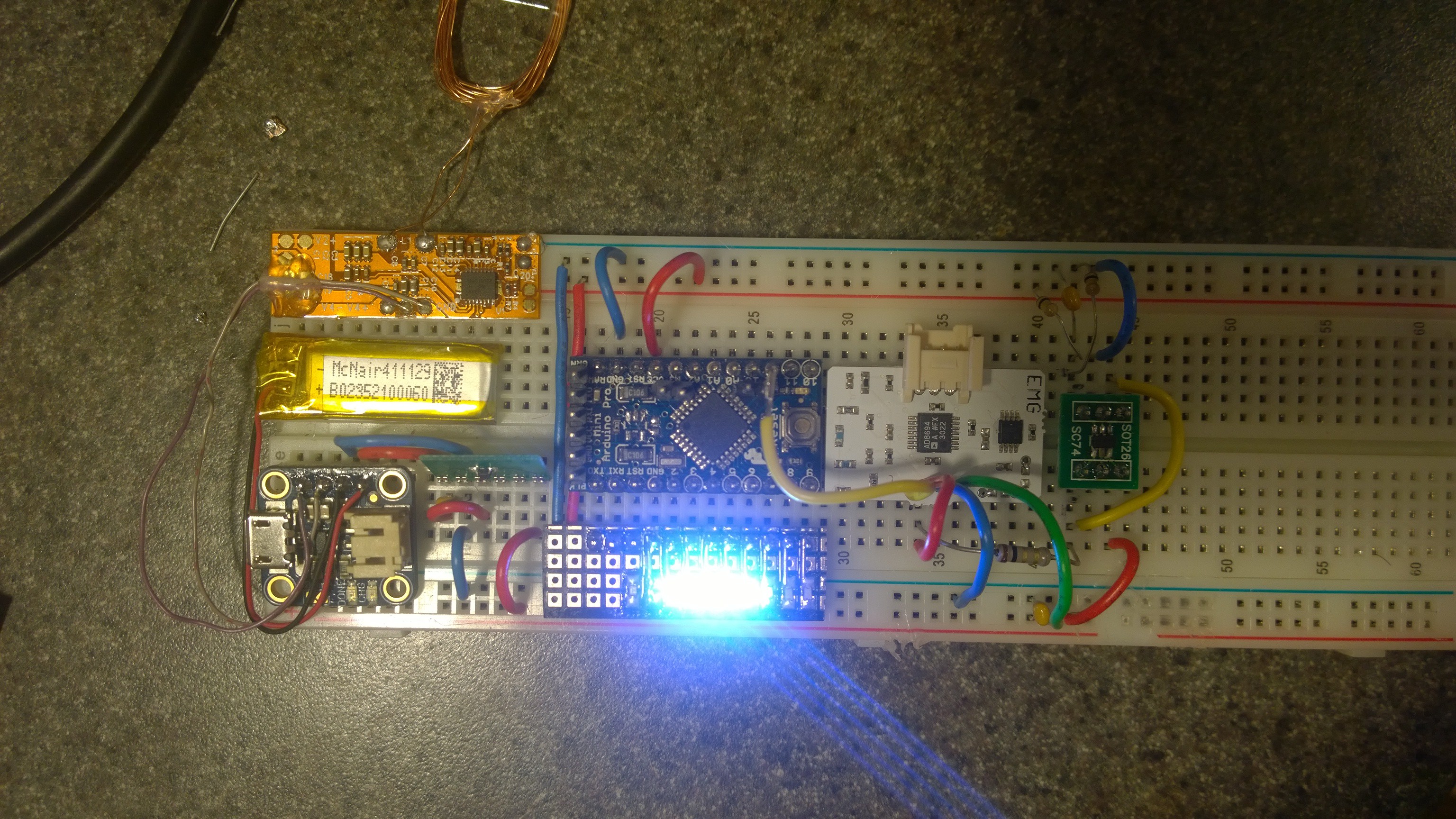
EMG and LED Bar Graph test
09/28/2014 at 11:41 • 1 comment![]()
Super Bright 0603 LED from Vishay http://www.digikey.com/product-detail/en/VLMW1300-GS08/VLMW1300-GS08CT-ND/2813370
How EMG circuit works you can find here https://github.com/txyzinfo/B10N1C/blob/master/Reference%20schematics/BITalino%20EMG%20schematic.pdf
-
HM-10 / HM-11 Bluetooth communication and Arduino remote reset
09/09/2014 at 14:55 • 0 comments![]()
Bionic Yourself V2.0
Project Bionic Yourself (B10N1C) is a small implant for your arm that makes you a bionic-superhero.