 Alex Bell
-
1Step 11- Gear System
Assemble the gears, first by screwing the m5 bolts through the jockey wheels and into the four positions on the gear supports. The fourth jockey wheel support is hinged on the gear support and connected through the tension spring.
![]()
-
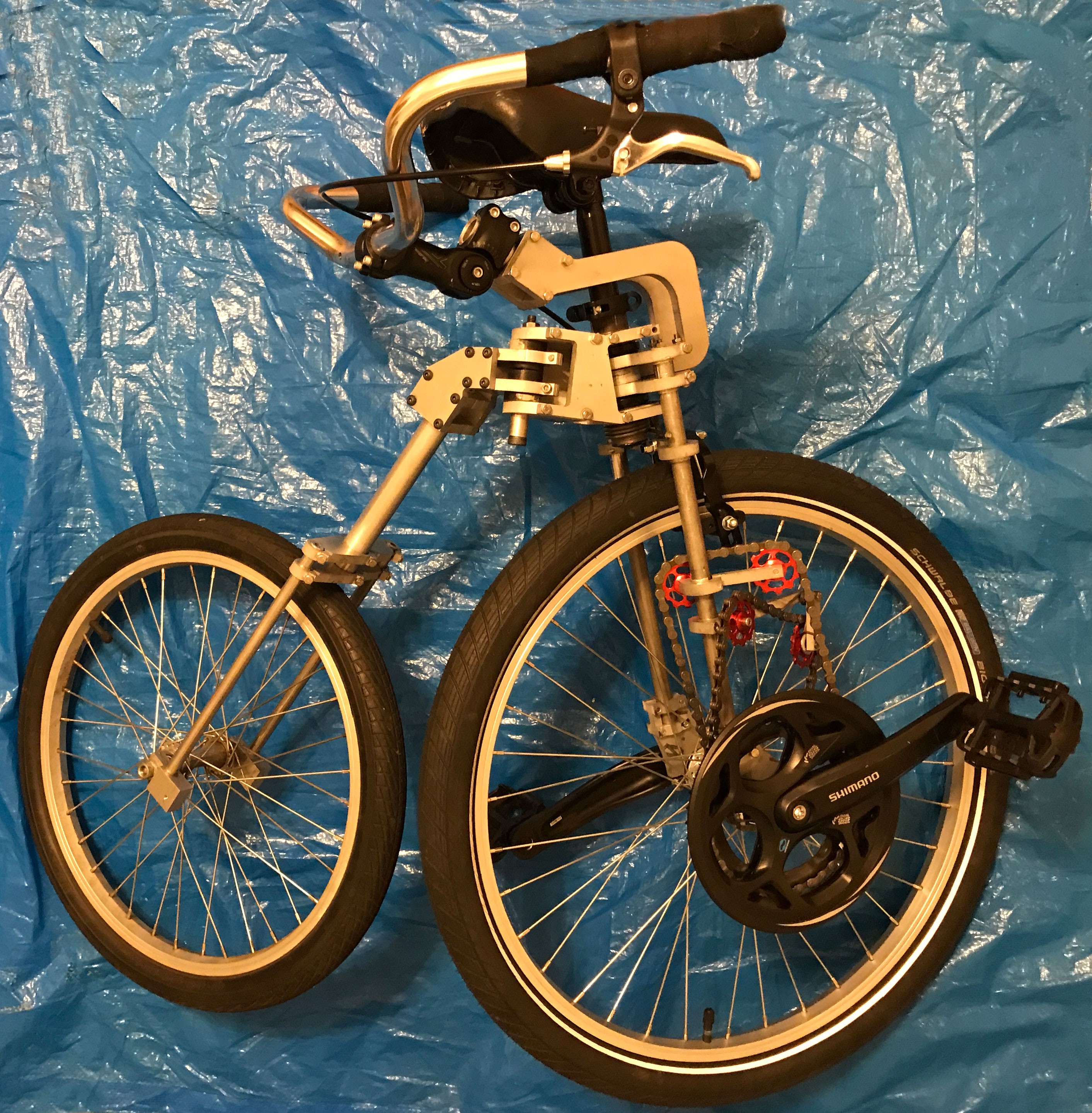
2Step 12- Test it Out
![]()
Adjust the seat so that you can still reach the ground when you are sitting on the bike seat, but just barely but comfortably.
-
3Step 2- Parts
Bellow is a list of all the parts you will need. There are only two kinds of parts which are custom and they are the waterjet cut aluminum frame parts and the axle spindle.
Waterjet Aluminum Parts
I would recommend you start by visiting https://gallery.autodesk.com/fusion360/projects/107744/bellcycles-v1-2-bicycle the CAD model and using the 3D viewer in Chrome to play with the model.
From there you can use the dxf file included in the project files or export a new DXF from the designs. You can use a waterjet cutter, plasma cutter, router, etc to cut the dxf file from .375" thick Aluminum 6061.
** Important. Depending on what machine you use you will have to take into account the accuracy and variation of the cutting. This may require some experimentation for each machine. A good example would be to cut a 1 inch hole in the material and then fit a 1 inch aluminum tube from the parts list into the hole. The hole should be .1" oversize for a nice clean fit.
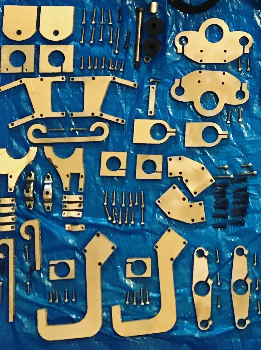
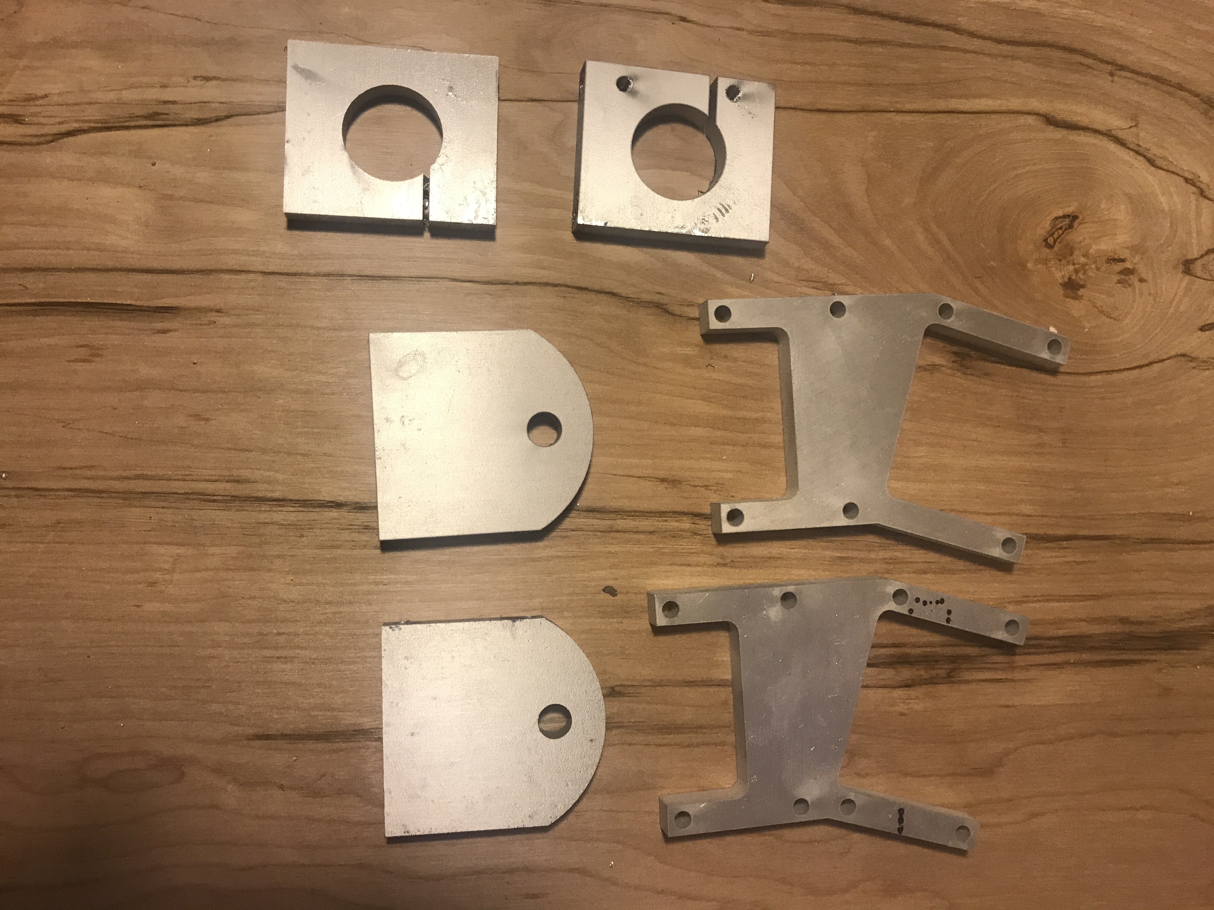
Once you have your parts use a file to knockdown and sharp edges left over from cutting and your parts should look like this.
![]()
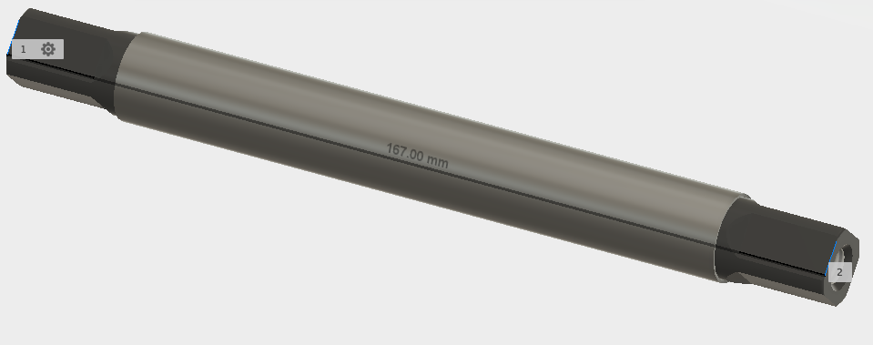
Spindle
You will also need a spindle to go through the front wheel. You can see in the designs above that the spindle is OD 17mm, 167mm Long and has standard square tapers.
![]()
- Machine Shop -If you have access to a machine shop this will not be too difficult to make. Start with a 17mm Rod and cut four tapers in each end according to the CAD files.
- Online Metal Shop- You can upload the design to a company such as eMachineShop.com and they can make you a spindle for around 100$ quantity 1.
- Home Solution- You can purchase a 17mm OD Rod (http://alcobrametals.com/product/1SRM17A) and then using a file or grinder carefully remove enough material to create a 2 degree angle. See the CAD for precise dimensions.
Parts
The bicycle parts are largely interchangeable so if you already have a seat, handlebars etc lying around feel free to substitute them in.
-
4Step 3- Tools
Drilling Holes
You will need to drill both clearance and tap holes for m5 bolts.
- Tap Drill 4.2 mm https://www.amazon.com/uxcell-Straight-Round-Diameter-Drilling/dp/B015A3BHKI
- Clearance Drill 5mm https://www.amazon.com/Metric-Magnum-Super-Premium-Drill/dp/B004XX479U
- You will also need something to drill these holes with, i.e. a drill. You could potentially drill these straight with a handheld drill if you are a very perpendicular person. If you are like me you will need a drill press https://www.amazon.com/WEN-4208-5-Speed-Drill-Press/dp/B00HQONFVE
Tapping Holes
- M5 Tap Set https://www.amazon.com/Irwin-Tools-2722-Piece-Set/dp/B003K15EQQ
- A tap wrench is nice to have https://www.amazon.com/gp/product/B004UUAJR0
Cutting Tubes
- Unless you buy the tubes cut to length you are going to need to cut them, a inexpensive hacksaw will do the trick. https://www.amazon.com/Stanley-STHT20138-Solid-Tension-Hacksaw/dp/B009CMV9D4
Bicycle Tools
- You will need a bicycle chain tool as well as a set of metric hex wrenches. I would get a nice multi-tool because then you can carry it with you. https://www.amazon.com/dp/B0012Q41HY/ref=twister_B003YMYX5E
Misc
- https://www.amazon.com/Forney-20857-Magic-Industrial-Cutting/dp/B003X3ZKXI Tapping Fluid makes the tapping easier.
-
5Step 4- Drilling and Taping Holes
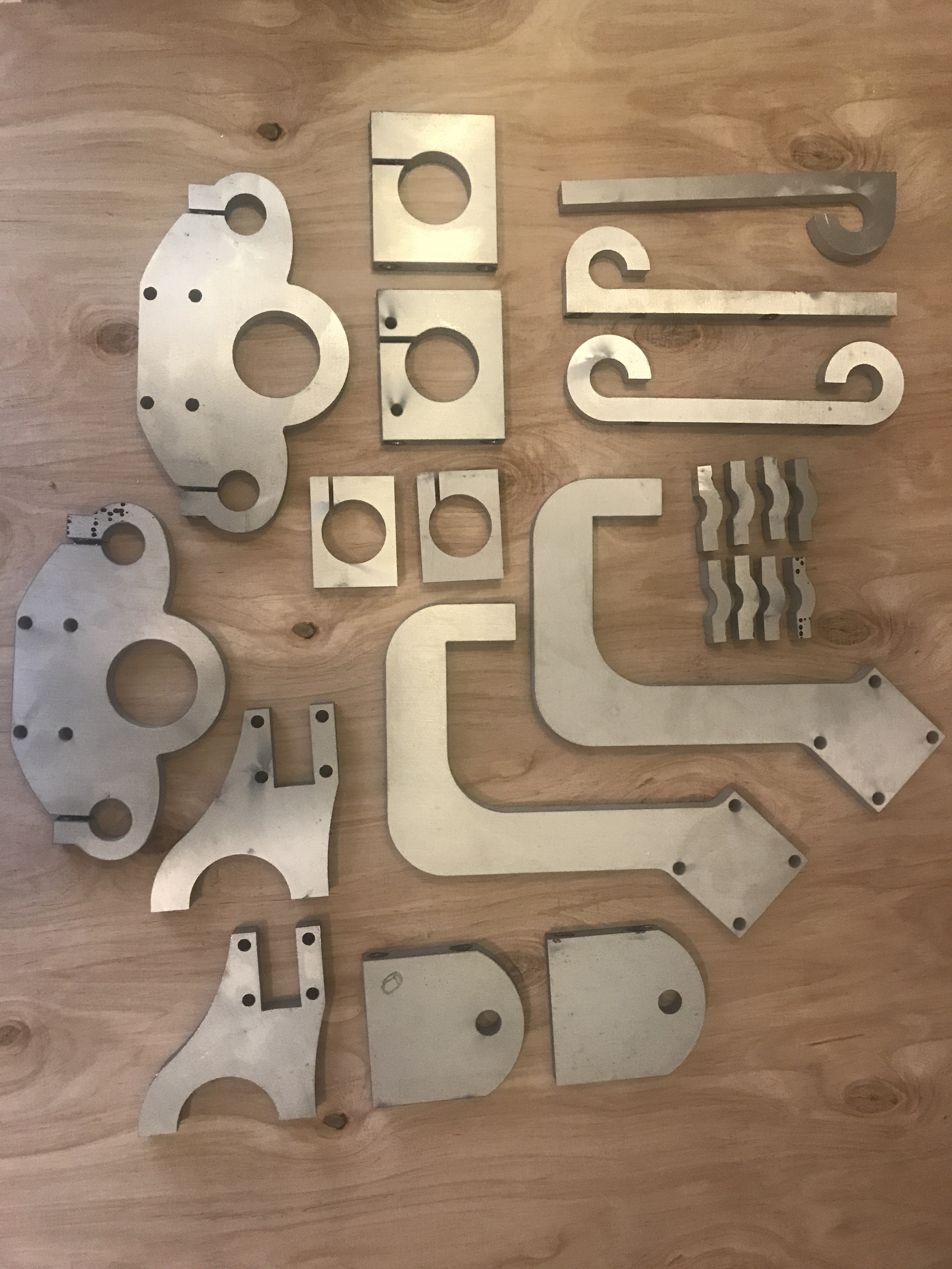
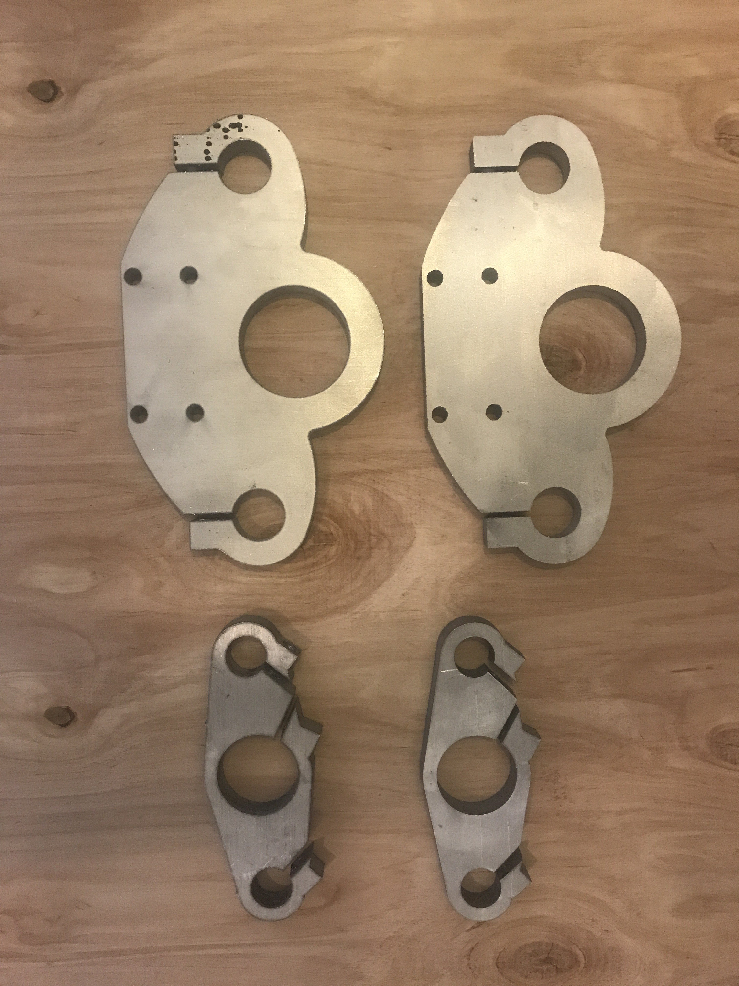
First step is to assemble all the parts that will need to be drilled and tapped. See the image below for the parts that need drilling or tapping.
![]()
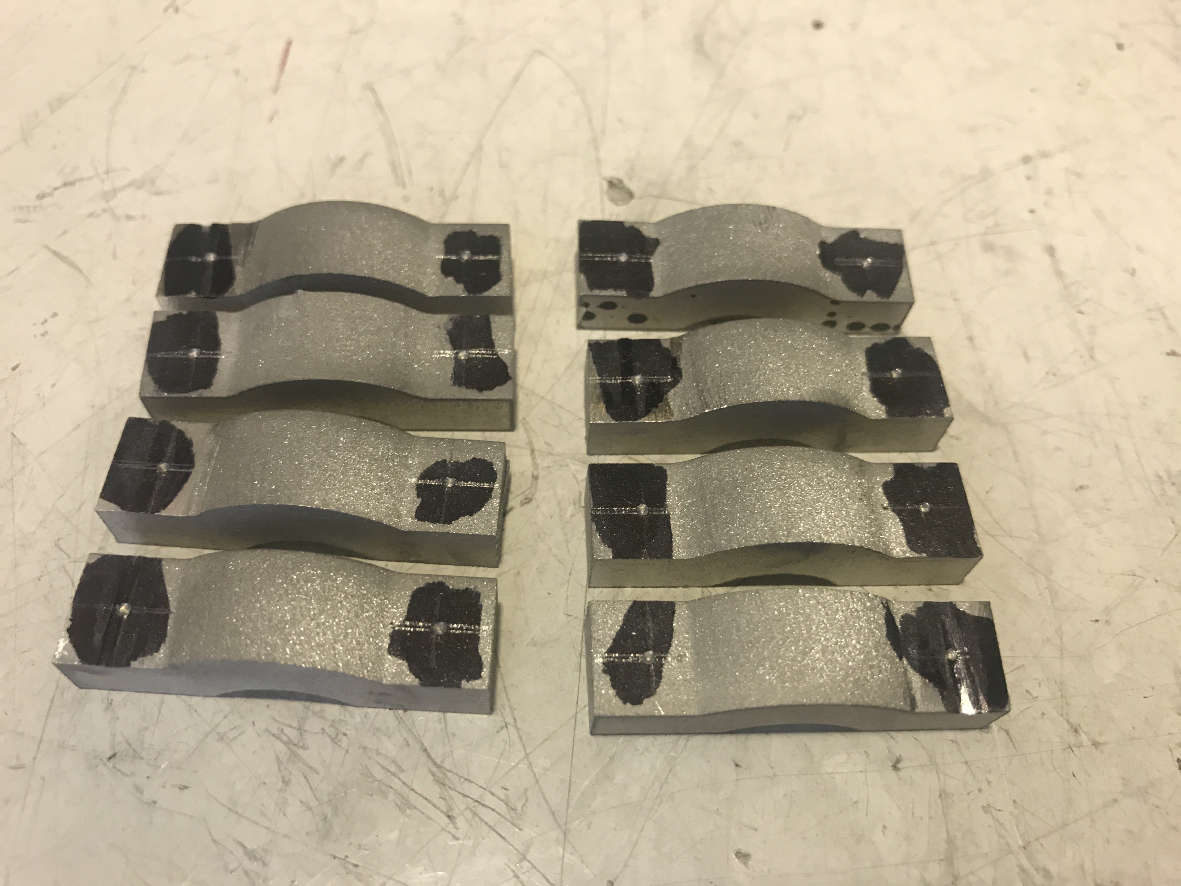
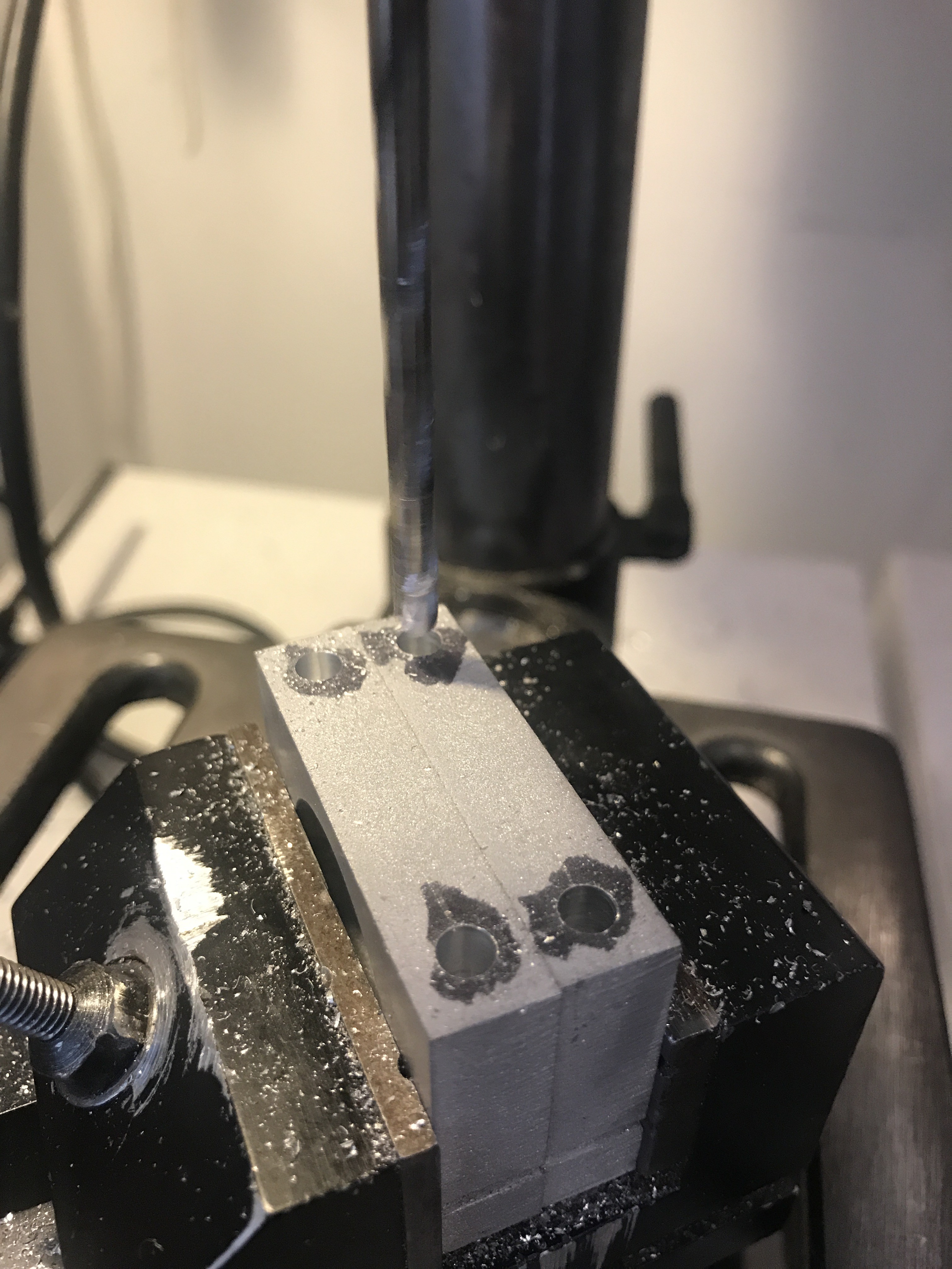
For each of these parts we will be drilling and tapping holes in the sides. Lets start with the easiest parts which are those shown below. These four parts need tapped holes and clearance holes on the tabs which are bolted down "pinching" the tubes.
![]()
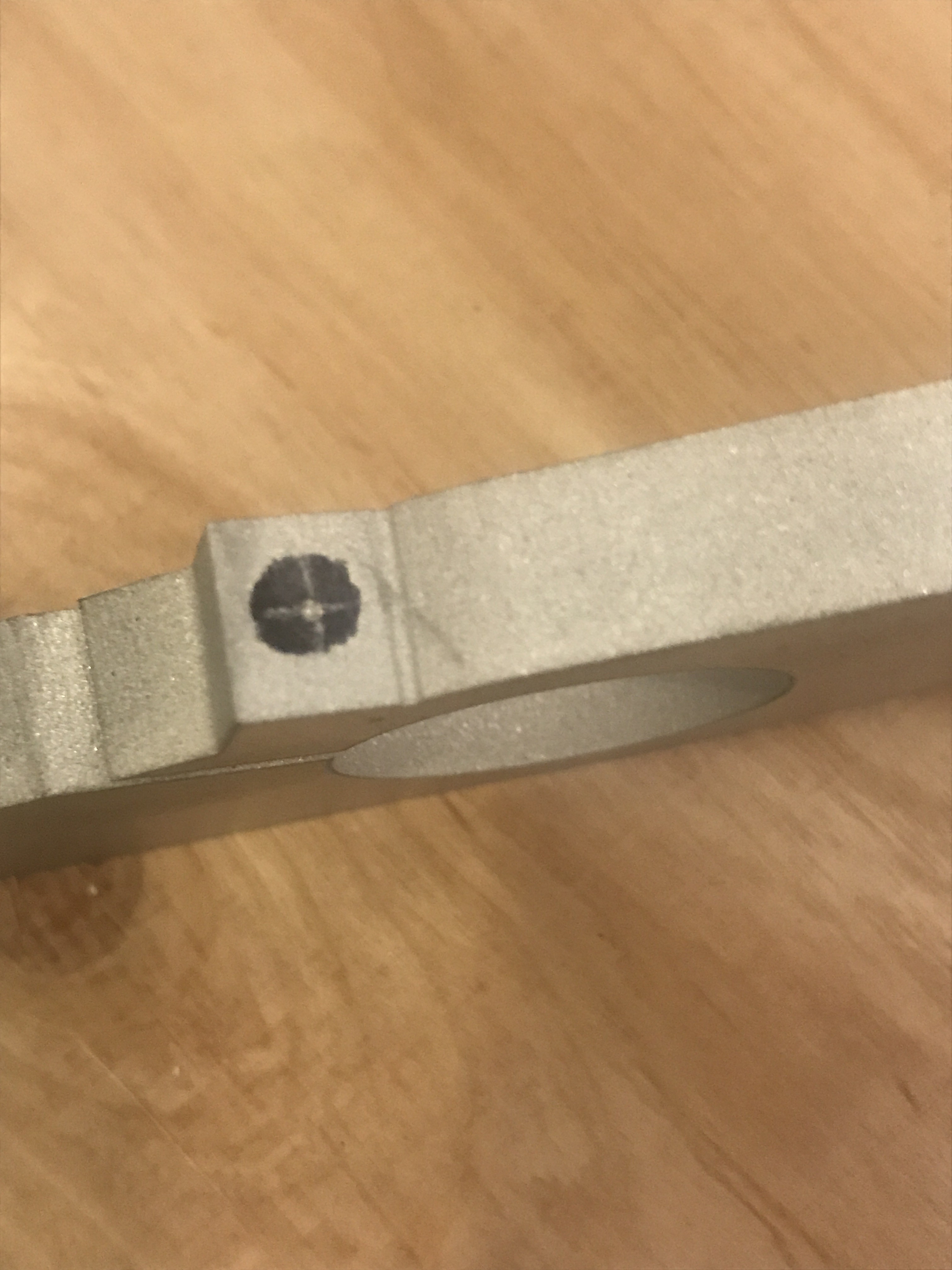
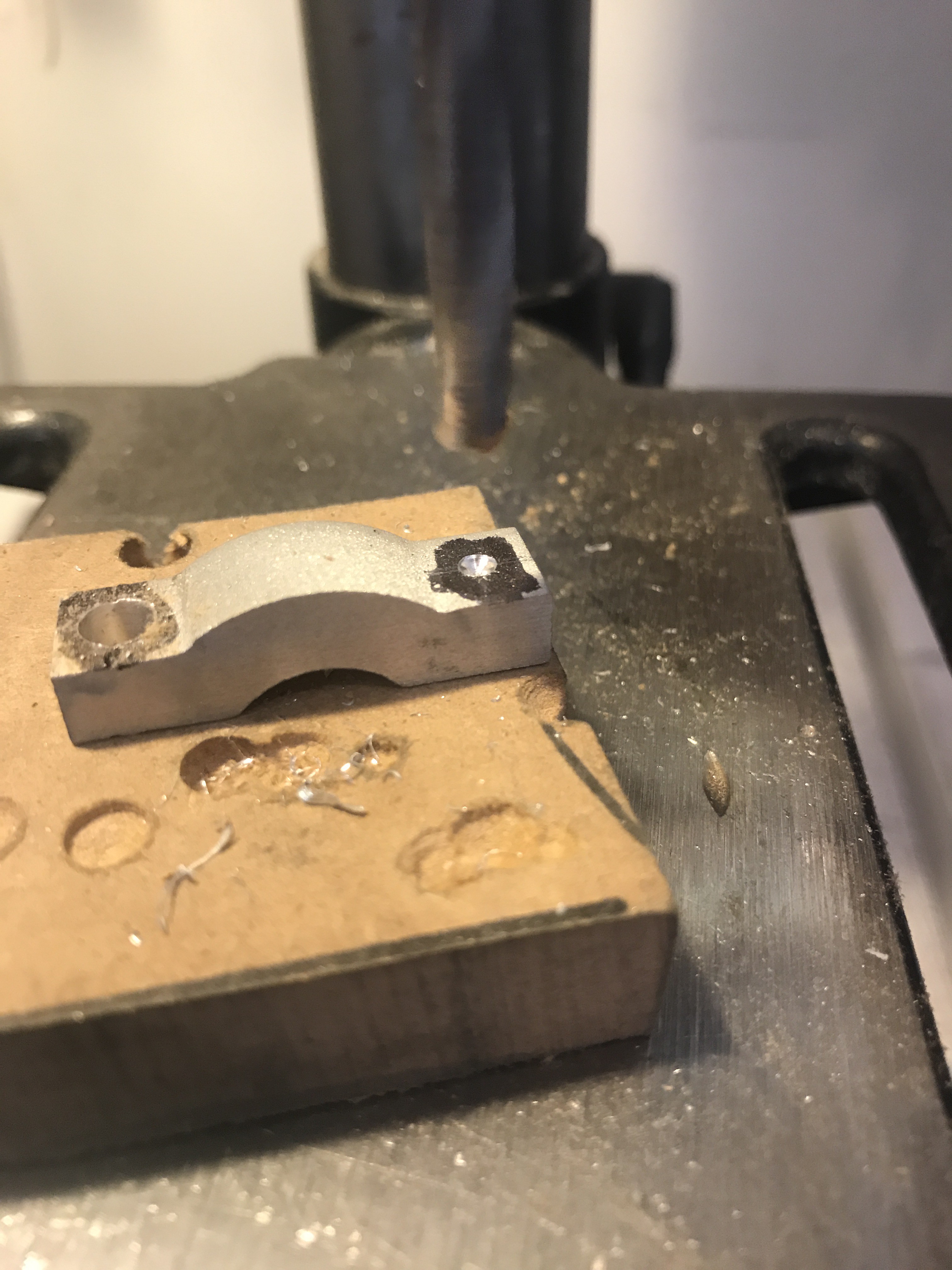
Make a mark in the center of the tabs and then drill the 4.2mm Tap Drill 30mm into the aluminum. The hole should be drilled perpendicular to the tab.
![]()
![]()
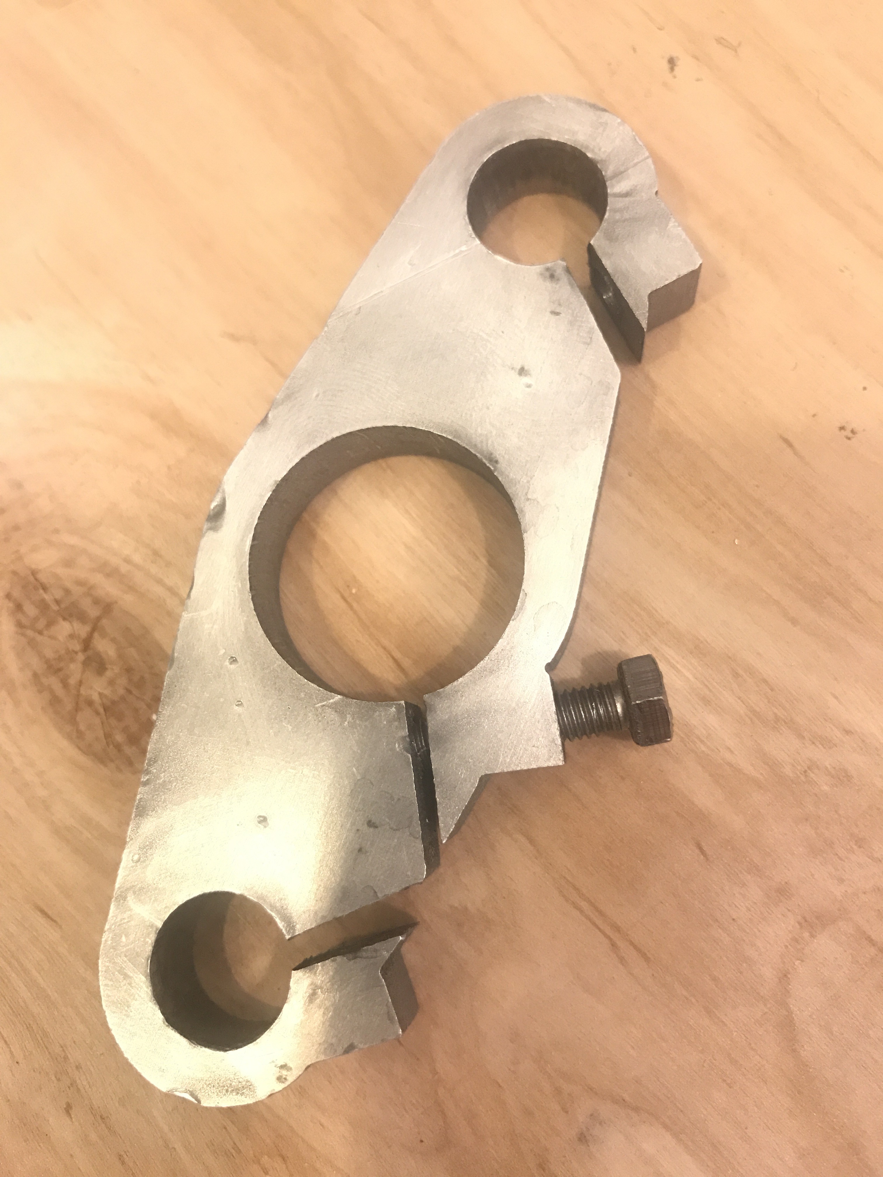
Then drill with the 5mm drill only through the top tab portion. Now a M5 bolt can pass easily through the tab.
![]()
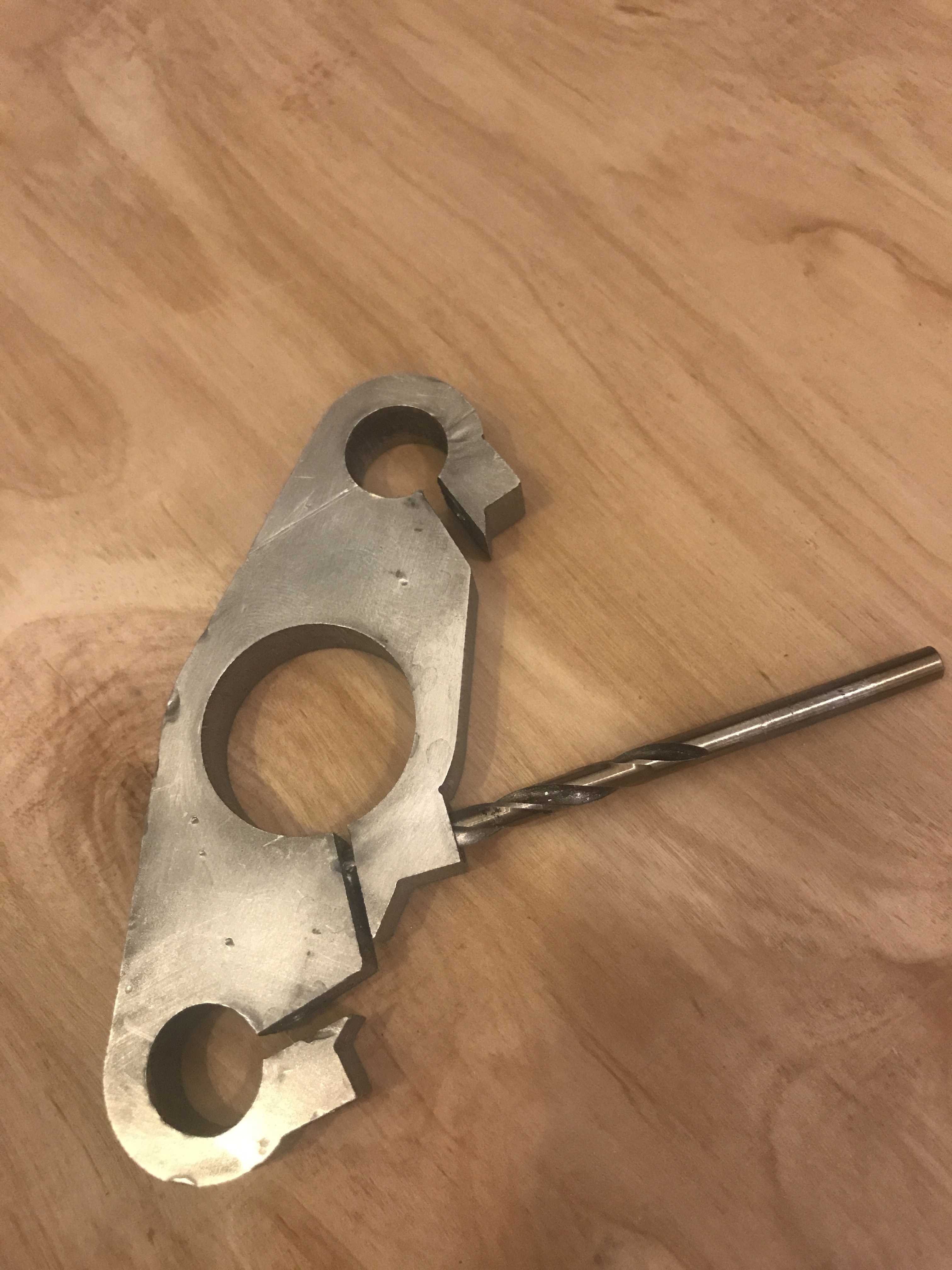
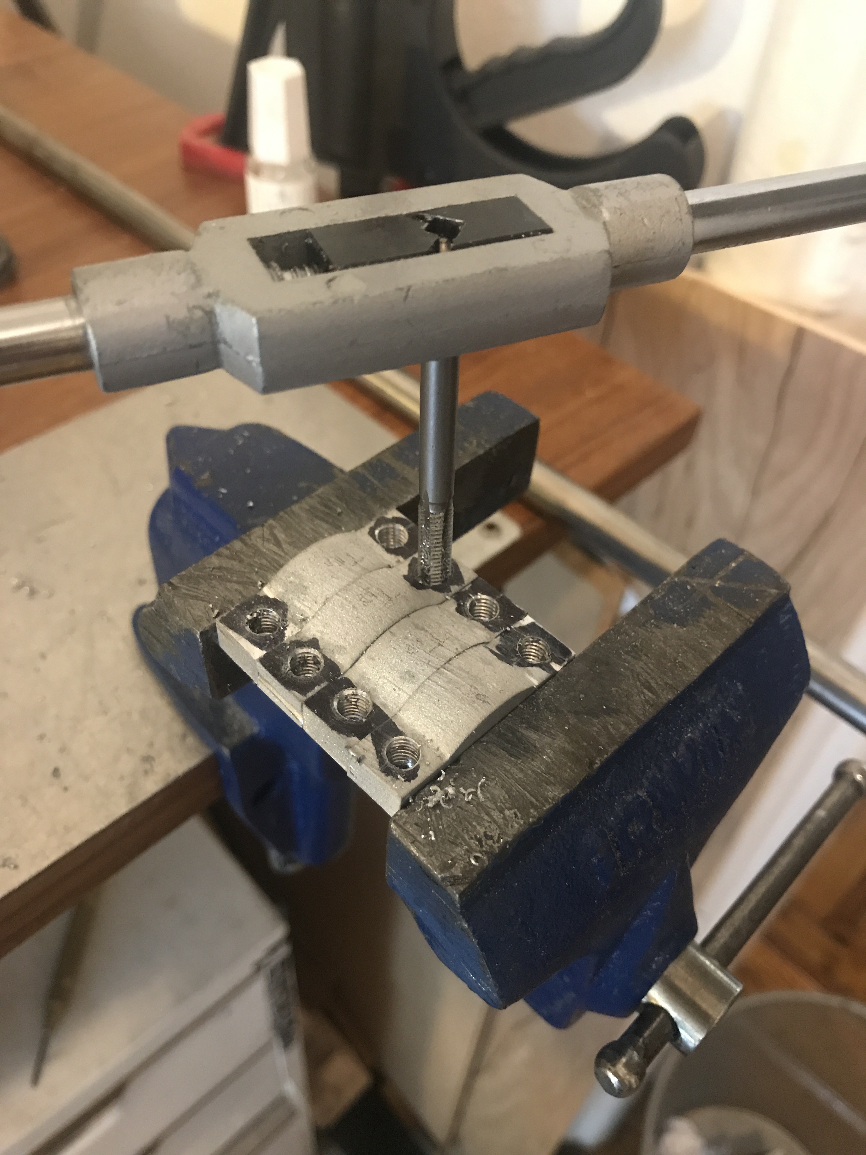
Now tap the hole making sure to start with a starting tap and end with the bottom tap. Take it slowly when tapping if you are new to this and make sure to take a half reverse turn of the tap every few turns to break the chip. Here ( https://www.kmstools.com/blog/hand-taps-proper-tapping-techniques/) is a good guide on hand tapping.
![]()
-
6Step 1- Overview
This is an illustrated guide to building a Bellcycles v1.2 Cycle from scratch.
This is the DIY approach. Hopefully in the future we can create a Kit which will replace some of these steps.
-
7Step 5- More Tapping and Drilling
Now we can drill and tap the remaining holes. Refer to the CAD design for finding the hole locations. For instance see the parts below which have holes in the middle of the width of the part and 5 mm from each side.
![]()
There are eight parts, 4 of them will be tapped and 4 will be clearance. So for 4 of them should be drilled with the 4.2mm drill and then tapped and the others drilled with the 5mm drill.
![]()
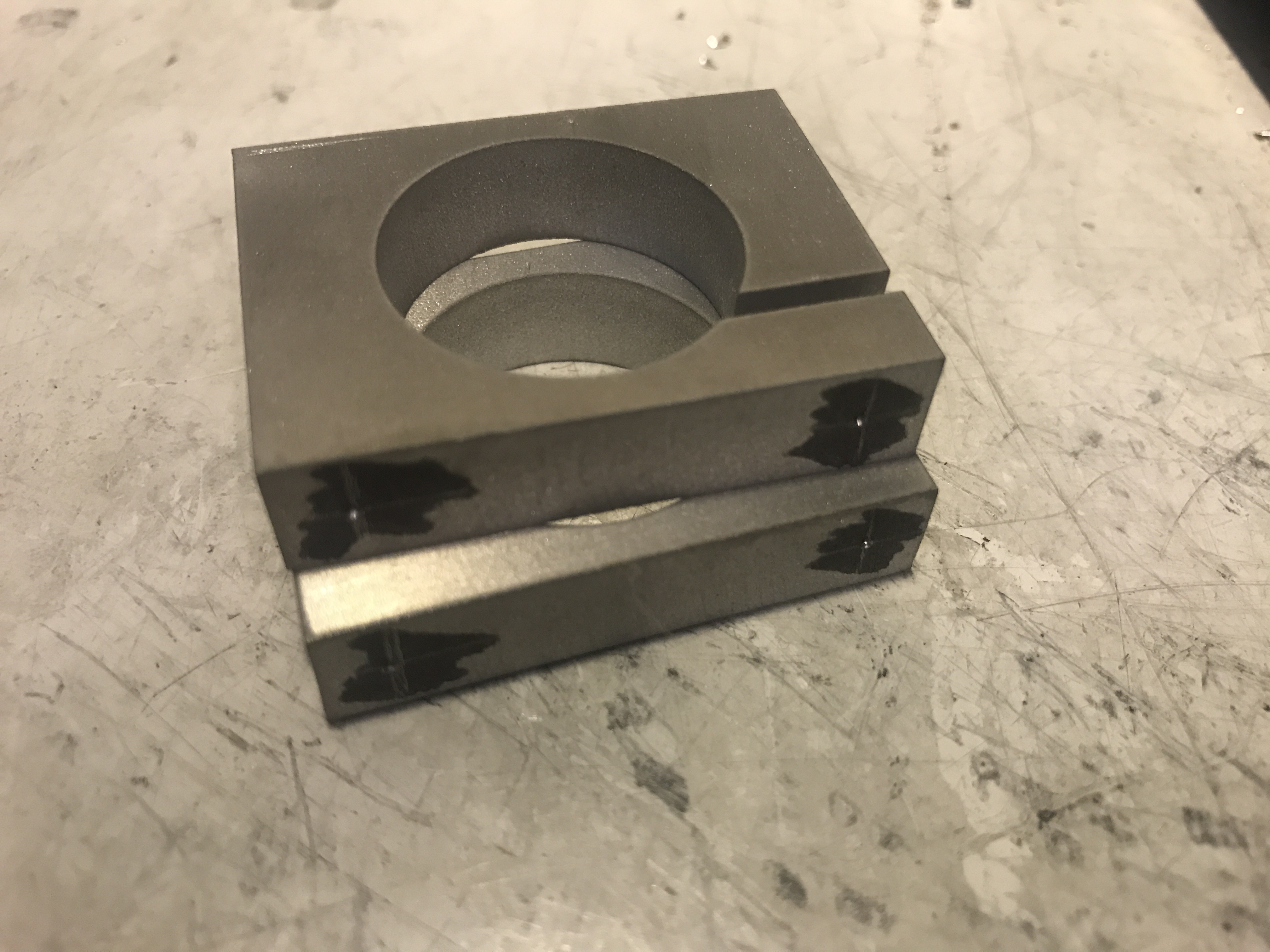
For the parts with slots cut in them, such as the two below, make sure to drill and tap the side with the slot 10mm more. So the standard tap distances are 15mm on this part per the CAD but the side with the slots should be tapped to 25mm. This is because the distance from the slot to the outer face are clearance holes. The slot and bolt serve as a mechanical "pinch" which secures the tube.
![]()
![]()
![]()
-
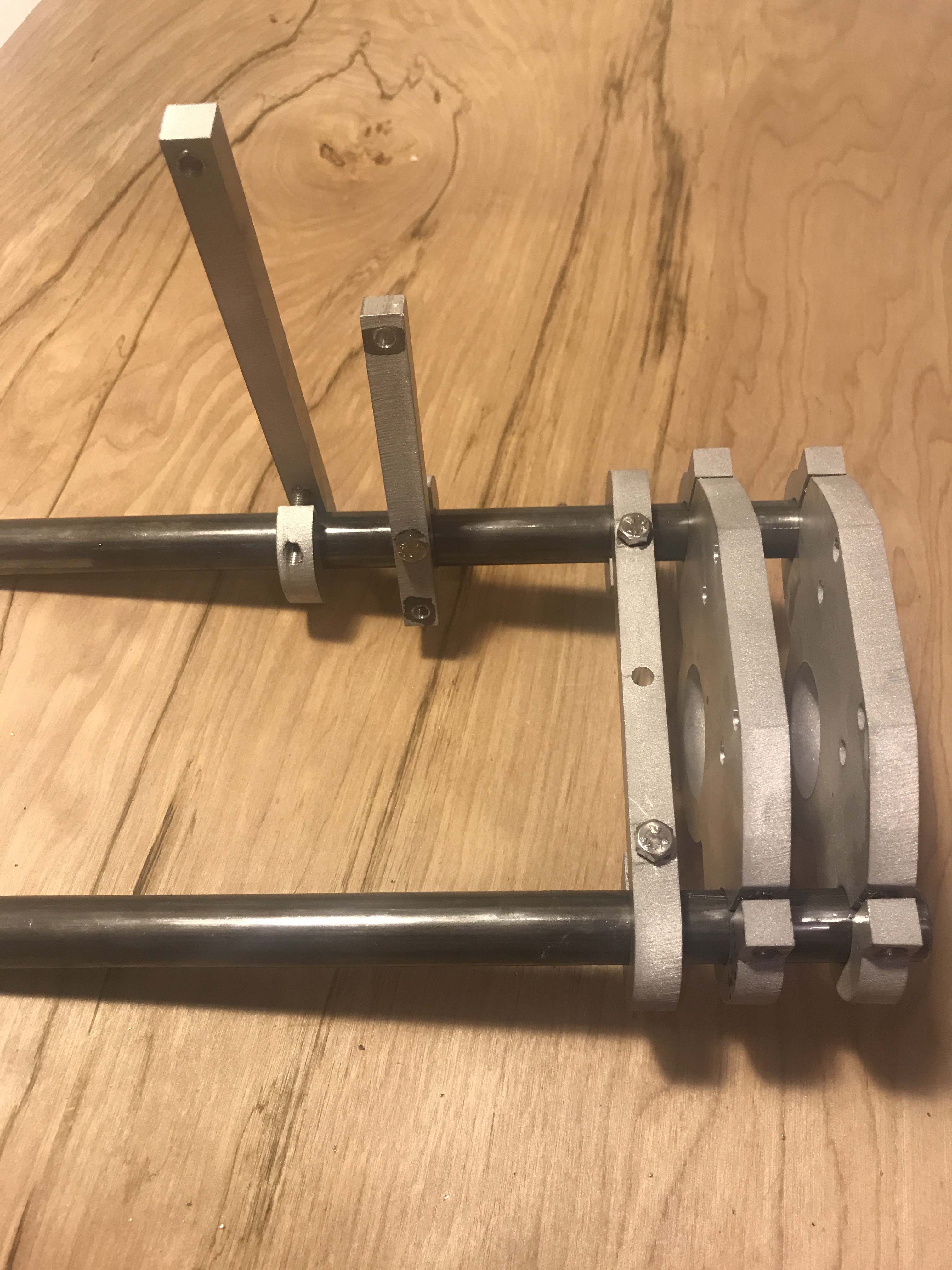
8Step 6- Assemble the Front Frame
To assemble the frame we will be using the 25mm long hex bolts in all the tapped holes except for those that are covering a pinch slot and for these we will use the 40mm long hex bolts.
![]()
Start by assembling the dropouts, each dropout mates to the .625" OD aluminum tubes.
![]()
Add the gear support pieces on the right tube as shown. Make sure to note the direction of the parts which should be alternated. After the gear support pieces add the brake support followed by the main triple tree supports.
![]()
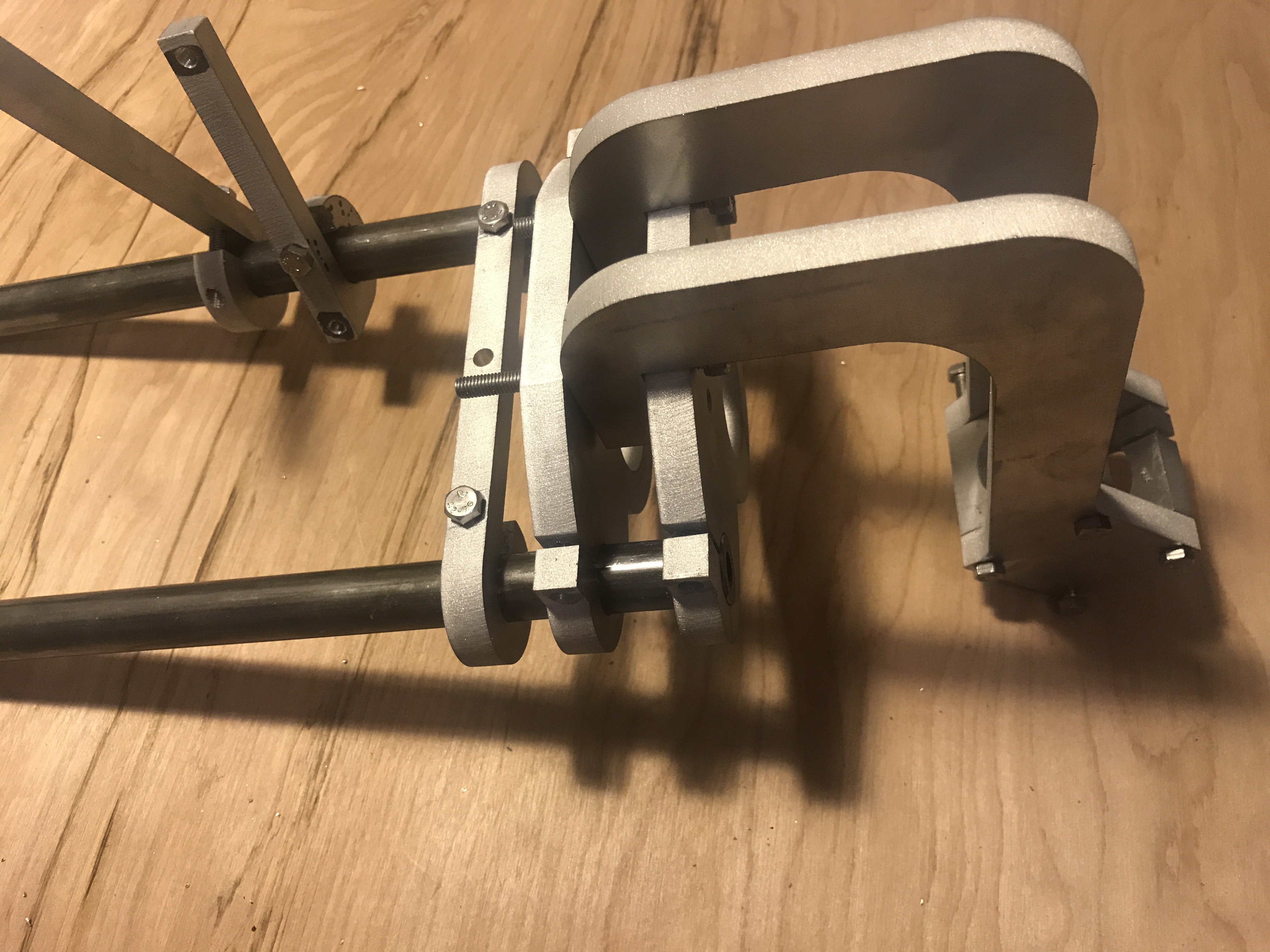
Then add the handlebar attachment using 4 long 40mm bolts.
![]()
-
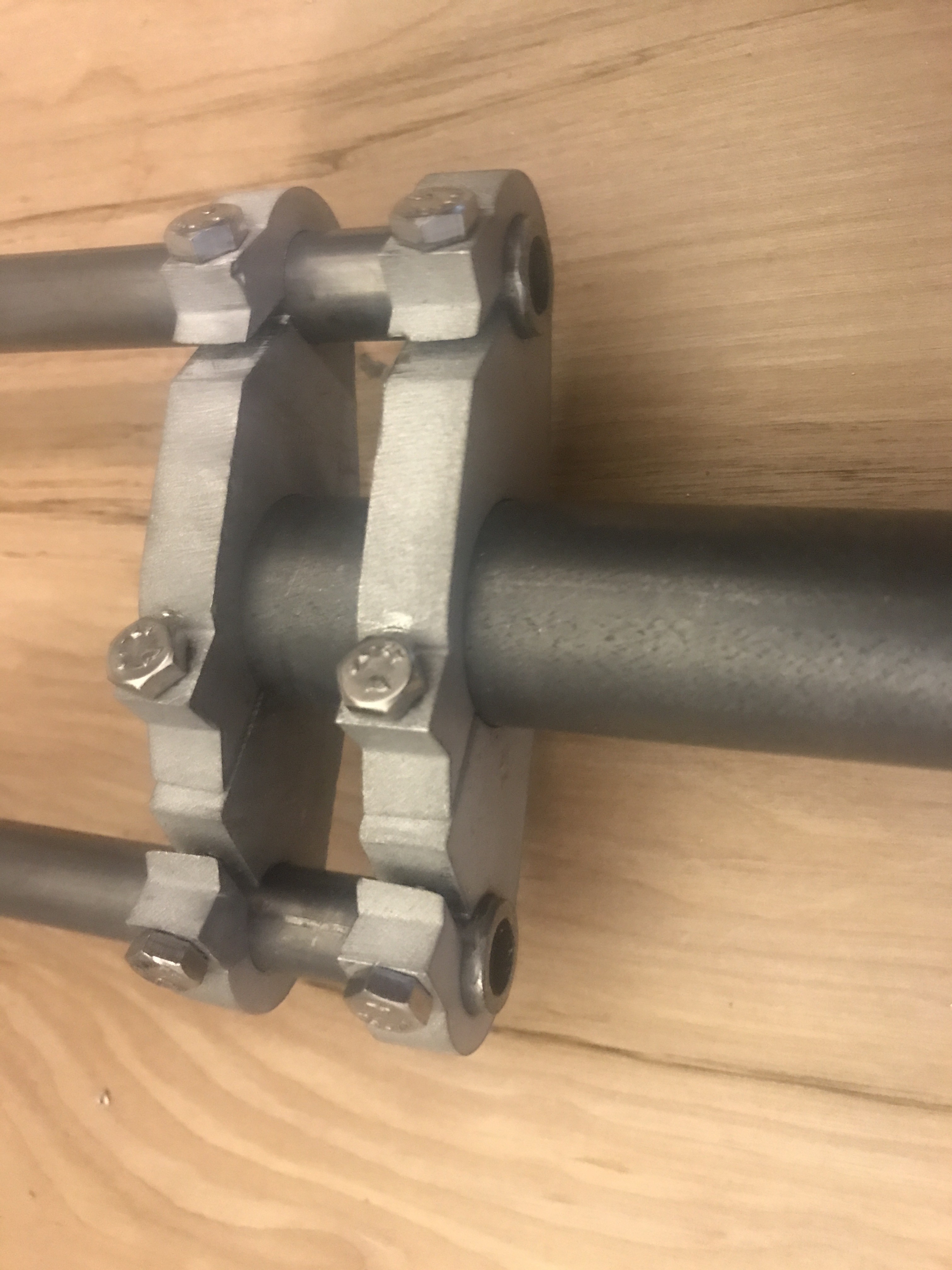
9Step 7- Assembling Center Frame
As in the front frame we will be bolting together the center frame using a combination of the 25mm and 40mm bolts.
![]()
Note the position of the openings when assembling. Also add the two bolts on the bottom of the center frame that will engage the torsion spring.
-
10Step 8- Rear Frame
Lets finish up with the rear frame. Slide the triple trees onto the two .5" tubes and add the main 1 inch tube.
![]()
![]()
Bellcycles: A New Take on the Bicycle
A front wheel drive, compact, modular bicycle that you build yourself.


Discussions
Become a Hackaday.io Member
Create an account to leave a comment. Already have an account? Log In.