-
1Step 1
Open up the switch tester. This is actually incredibly troublesome and the reason why I opted to use an external battery.
-
2Step 2
Program your atmega. Remember that since this is battery powered and the nrf24l01 needs 3volt, you need to set the fuse bits to clock it down to 1 MHz. This will allow the atmega to run from 1.8v to 3.3v so it can run off a single button cell battery. You should also turn off brown out detection since that just wastes battery.
-
3Step 3
![]()
Prep your atmega328p by bridging the power and ground pairs. Some pins may also need to be bent to fit it into the enclosure. this will vary by where you choose to mount it.
-
4Step 4
Go ahead and solder on the nrf24l01 using some ribbon cable. If your nrf came with pin headers its best to remove them and solder the ribbon cable in its place.
![]()
-
5Step 5
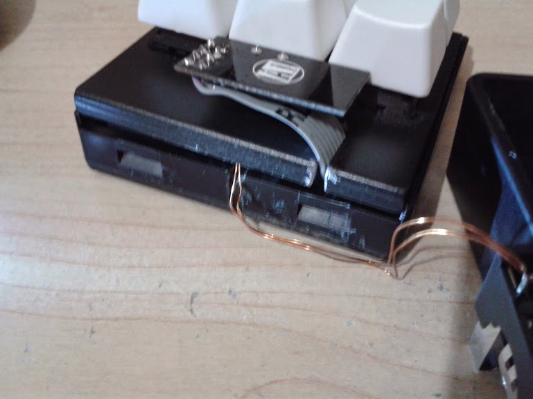
Cut a notch in the steel plate that is large enough to accept the ribbon cable. I used a dremel but a file would do fine too.
![]()
-
6Step 6
cut a notch in the bottom plastic case to allow wires a place to come out to attach to the battery.
![]()
-
7Step 7
Wire up the keys. Theres only 6 keys, so matrixing doesnt really buy you anything here. I'll be using the internal pullups, so i just ganged one terminal on each key and wired that to a ground. Then each of the others went to an analog pin (pin C). Pin C is unused by the nrf24l01 so we can simply read in pin c as a byte and do some bitwise manipulations to see which keys are pressed.
![]()
note: The provided source code assumes you will be using the analog pins as your keyboard inputs.
-
8Step 8
Put the atmega in its final resting place. I find it fits perfectly squeezed behind one of the back posts.
![]()
-
9Step 9
with the atmega in place, feed the nrf24l01 through the slot in the switch plate
![]()
-
10Step 10
replace the lid.
![]()
 Rob
Rob


Discussions
Become a Hackaday.io Member
Create an account to leave a comment. Already have an account? Log In.