-
Production Finshed, Badges Have Arrived
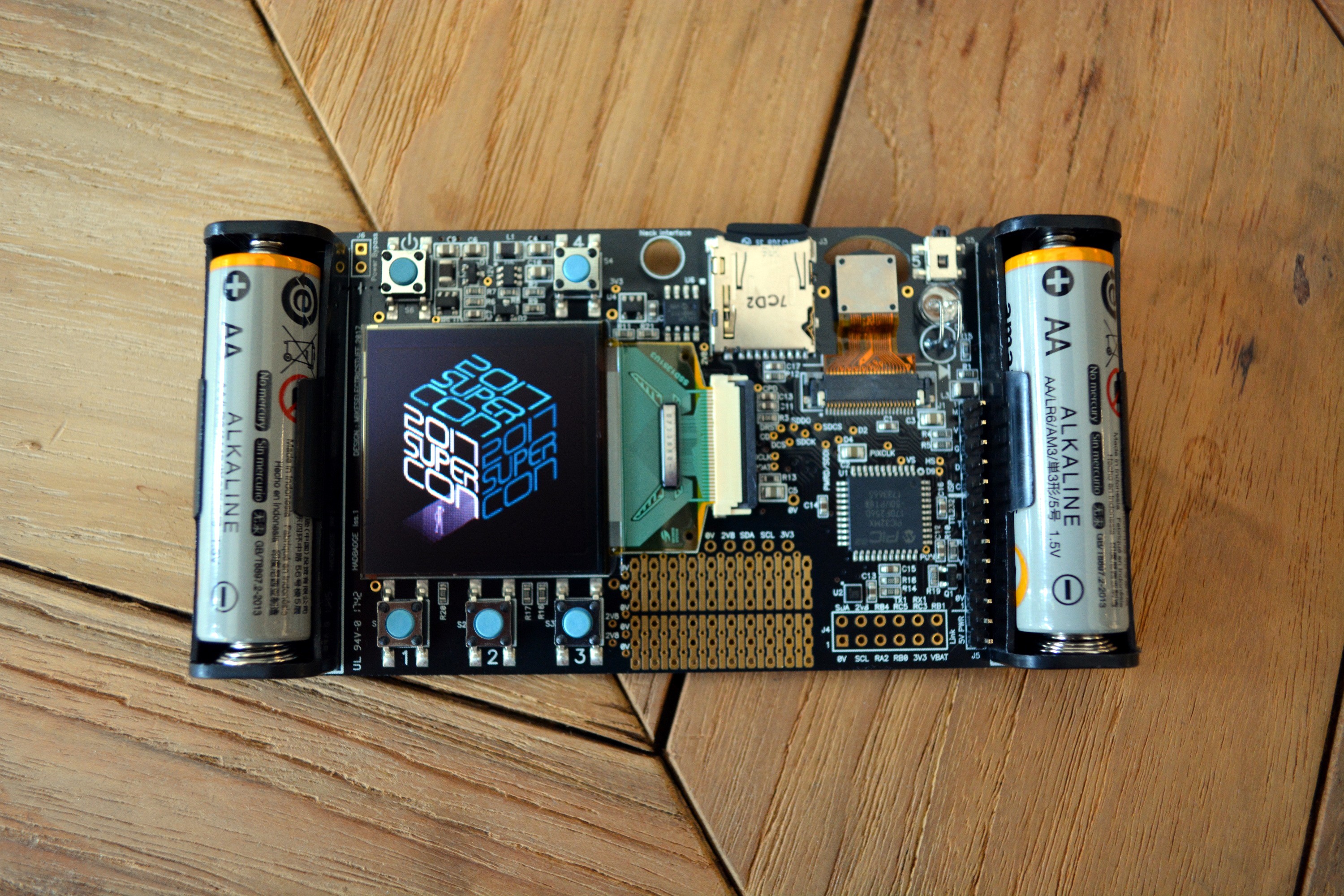
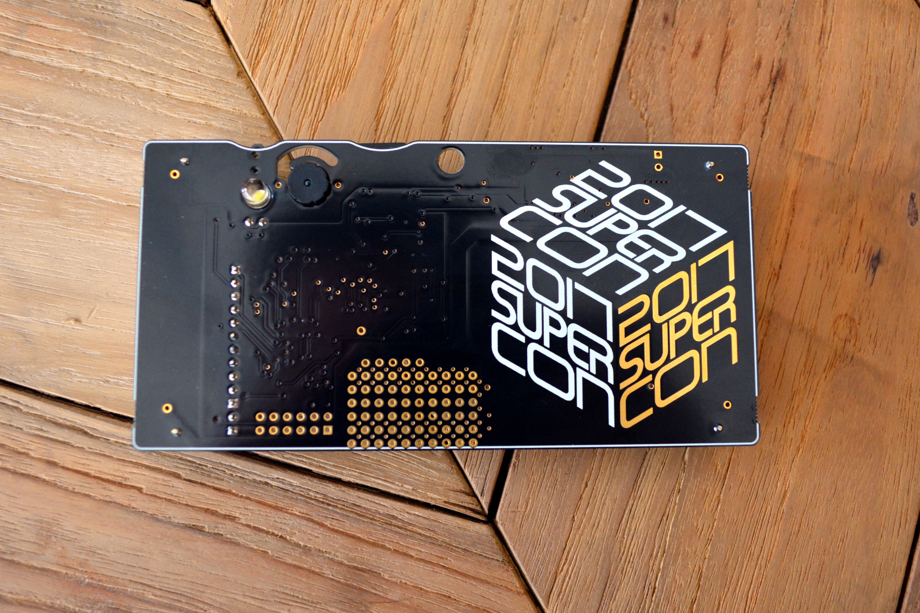
11/08/2017 at 00:22 • 2 commentsNumerous boxes arrived today from Macrofab, the Contract Manufacturer who handled fabrication of the badge. After quickly unwrapping the first board, we popped in a microSD card and are happy to report the production run is a huge success.


We have many more images to share so join us below for more.
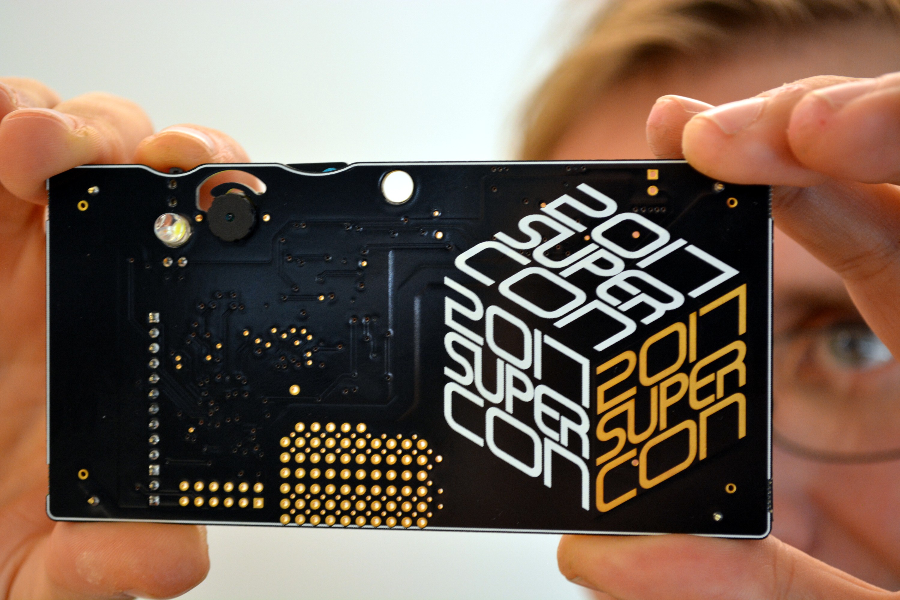
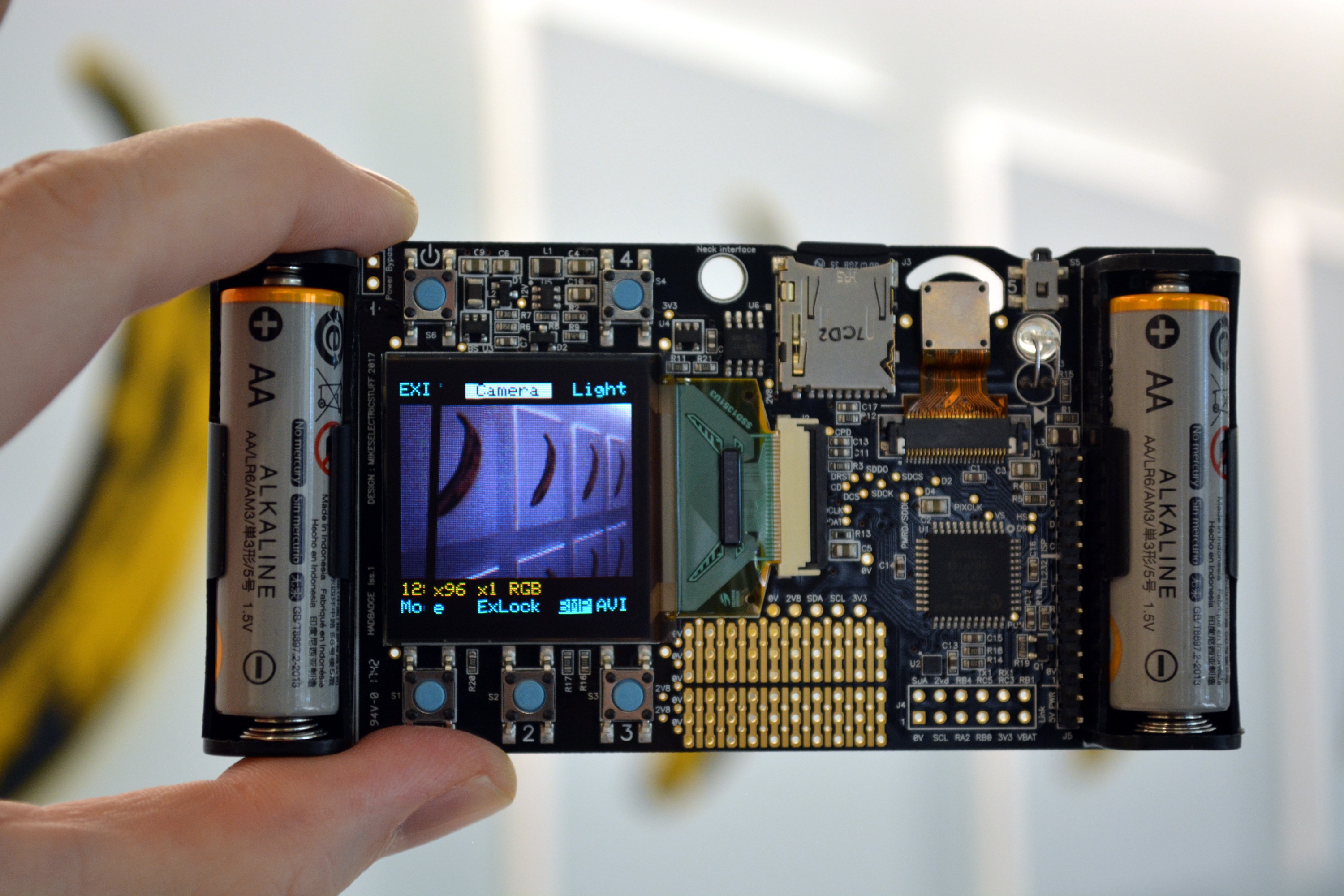
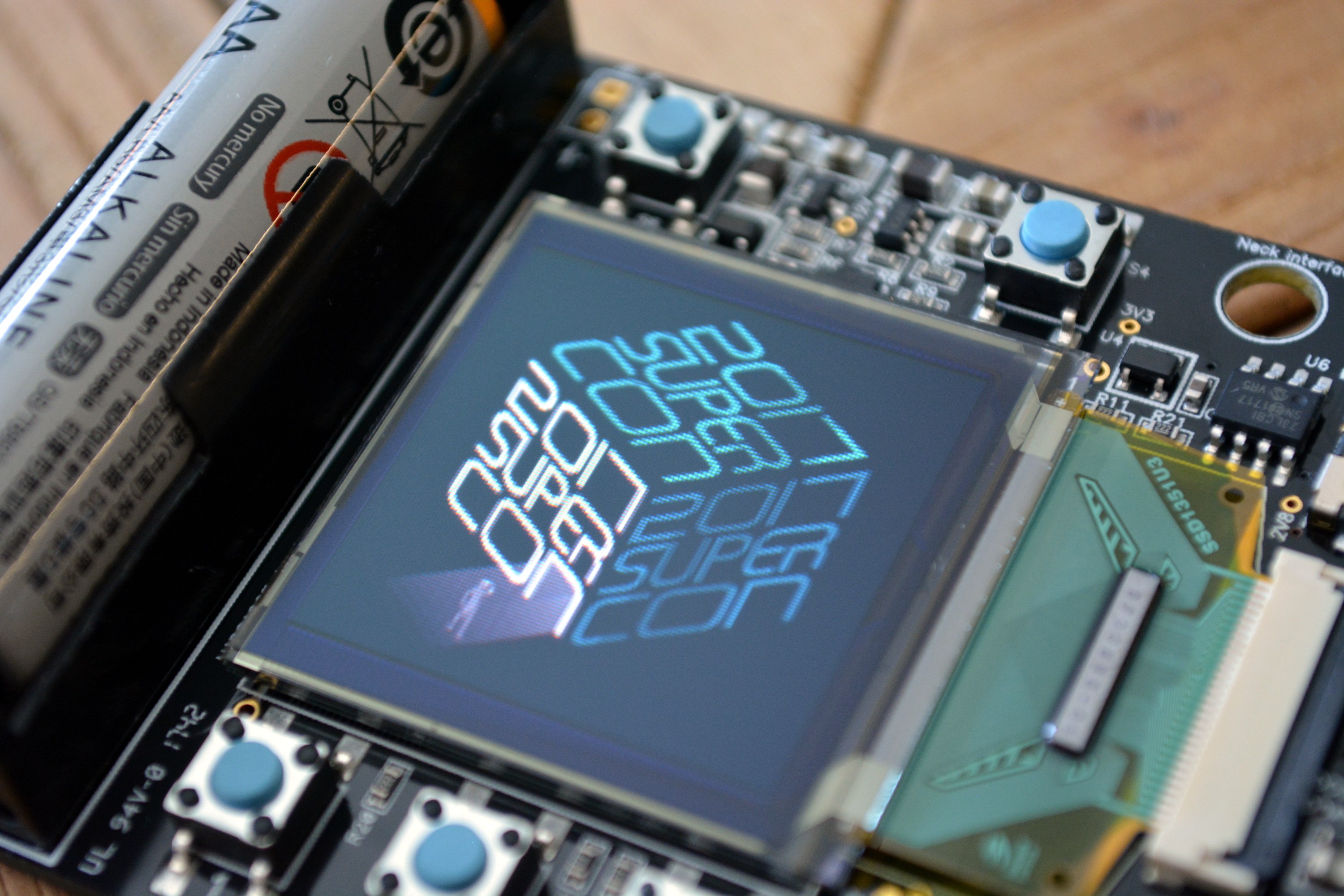
---------- more ----------At its heart, the badge is a camera and the form factor and features fully embrace that. It has an LED to serve as the "flash", a live viewfinder displayed on the OLED, and the shutter release is in the upper right where you'd expect it to be on a camera.


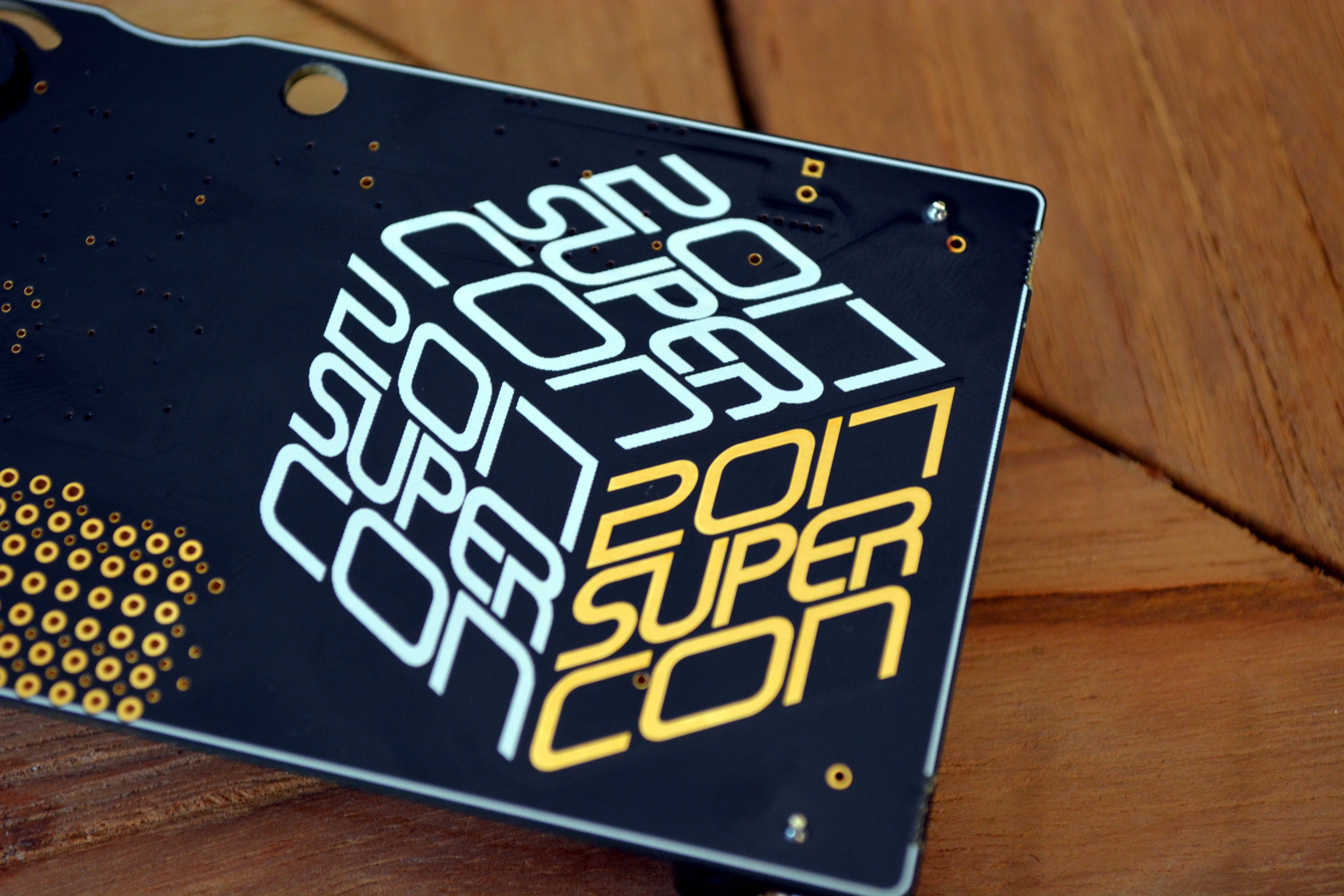
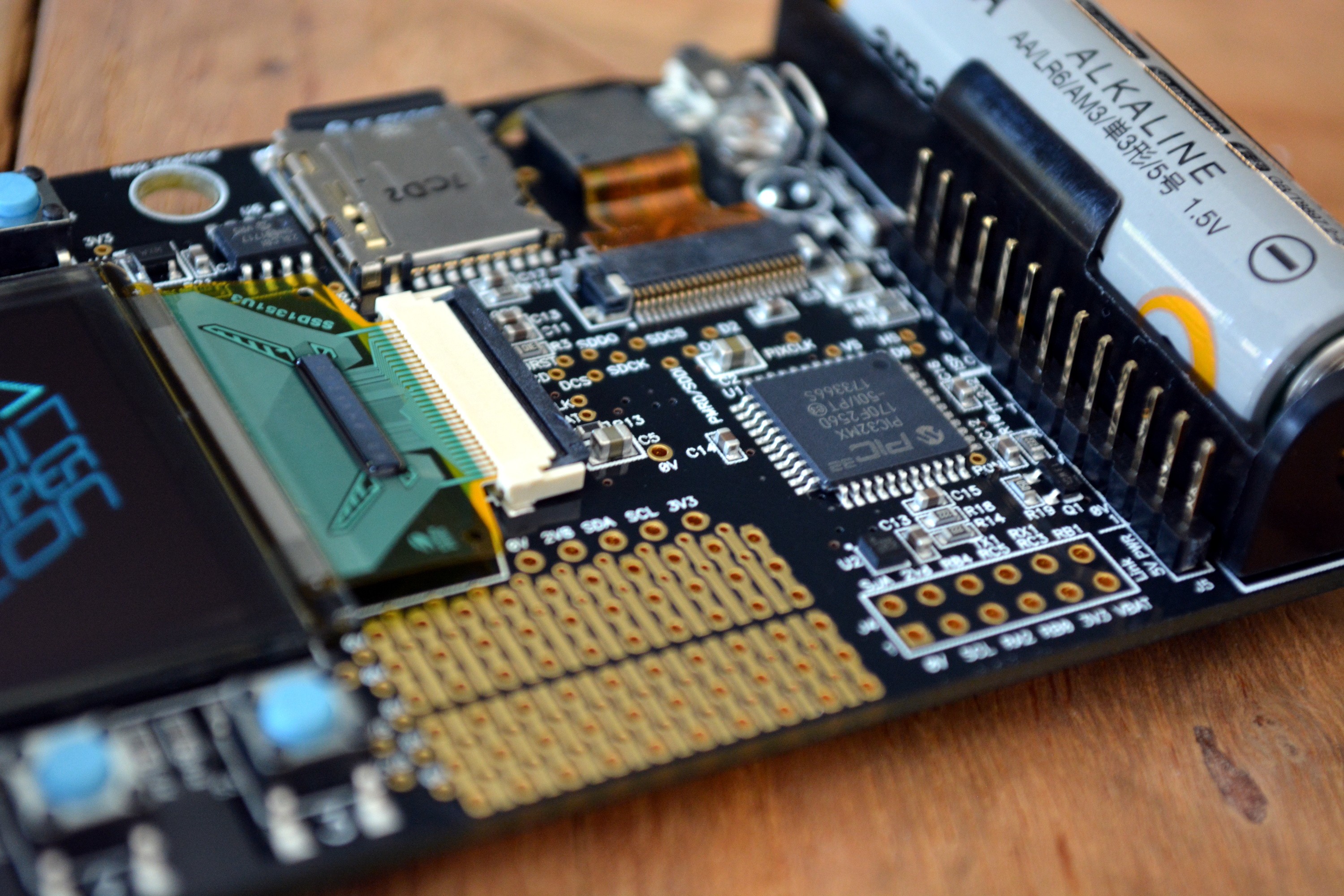
Here so some beautiful shots of the board itself.


-
Hardware description
10/11/2017 at 11:11 • 4 commentsPower supply
Supply is from two AA cells, nominal supply voltage is 2 to 5V ( startup). Once running it will continue to operate down to about 1.2v, depending on load ( in particular OLED content).
Incoming power feeds a MCP1640B boost regulator U5, which boosts the supply to 3.3v.
If the incoming supply exceeds 3.3v, the regulator bypasses, connecting the output to the input, so this must be bourne in mind if the 3.3v supply is used to feed 3.3v-only devices, as the 3.3v rail will be close to the input voltage for inputs >3,3v This is not an issue with alkaline AA cells, but may cause unwanted smoke if supplied from other power sources.The 3.3v supply is then regulated down to 2.8v by U5 which supplies all onboard devices except the OLED boost supply and white LED.
The OLED boost regulator U3 provides nominally 12.7v for the OLED. The input to the boost inductor comes direct from the battery, but the boost regulator is supplied from the 2.8v supply. This to allow operation when the battery voltage falls below U3's minimum supply voltage.Power on/off control is via the MCP1640's ENABLE input. The power button forces the device on via D2A. When the MCU starts, it then holds the pin high using IO pin RA4 via D2B, and can power down by setting this pin low. The state of the power button can be read via RA7.
Battery voltage sensing
Q1 switches on a voltage divider to allow the battery voltage to be measured. As Q1's source may be higher or lower than the PIC's 2.8V supply, C12 is used as a level shifter. The POWERCON signal is set low for a very short period while the ADC samples. This period is short enough that the 3.3v supply is not affected by the momentary turn-off of U5. Battery voltage is measured relative to the PIC's internal voltage rererence, so correct results are obtained if the 2.8V rail starts to drop out.Camera
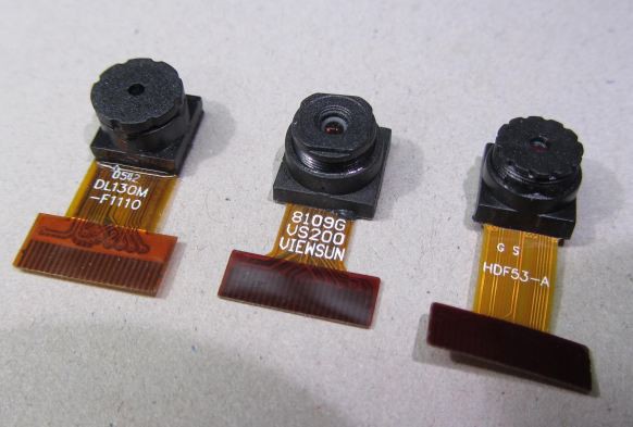
The camera module uses the OV9650 sensor from Omnivision. There are a number of slightly different modules available on Ebay and Aliexpress. The ones pictured below have been tested & found to work with the badge hardware. There may be slight differences in lens field of view between module types.
This sensor is one for which quite a lot of documentation has escaped ( see files section ), though this should still be treated with caution as descriptions of the registers are incomplete, sometimes misleading or just wrong.
The PIC reads data from the camera via the parallel master port (PMP) peripheral, via DMA transfers triggered by counters clocked by the pixel clock. The basic method used is described in This video
The method described in the video only captures single pixels every <n> pixels, where n>1 , as the counters cannot generate a DMA request on every clock. This works for monochrome format as you only need the Y component of the YUYV output sequence.
This technique has been further developed In order to capture adjacent pairs of pixels necessary for the RGB565 colour format.
This works by doing 2-byte DMA transfers, and relies on the pixel clock period being the same as the time between the two consecutive DMA transfers. There is a small amount of jitter on the time of the second transfer, but by selecting the PIXCLK phasing, this is kept within the data-valid time of the camera data. For slower capture rates it may be possible to tweak the 2-byte transfer timing using the PMP peripheral's wait-state configuration.The camera's POWERDOWN line is controlled by one of the OLED's GPIO pins. This is of limited use in practice, as when the camera module powers down, it jams the I2C bus for a second or so as the core voltage discharges ( causing the regular accelerometer reads to hang) , so this should not be used for routine on/off control, but only if a soft powerdown mode is needed. The camera's sleep I2C commands allow the camera to be put in a reasonably low-power mode.
One issue that has been observed is that when underclocking the camera below 12MHz ( which is necessary for some of the zoomed modes), Accessing the I2C bus at >100Khz can put the camera in a state where it jams I2SC SDA permanently low. Briefly pulsing POWERDOWN high seems to clear this condition.
OLED Display
The display is a 128x128 pixel colour OLED, using a SSD1351 controller via a unidirectional SPI interface.OLED was chosen over TFT as it only consumes power propotional to the pixels illuminated, whearas a TFT draws significant power for the backlight all the time.
One of the controller's GPIO pins is used to turn the 12V supply boost converter on and off. This can be used if a soft powerdown function is needed.
This display is available as a Densitron part ( DD-128128FC-6A) from Farnell, 4D Systems (4DOLED-282815) from Digikey, on this module from Adafruit and This one from Sparkfun
However the same module is available at much lower cost from Aliexpress and Taobao: search for 1.5" OLED and look for this image:MicroSD card
The MicroSD card is driven via the SPI interface. The CS line is also used for card-present sensing, and the SPI lines are shared with the serial SRAM.
Accelerometer
U2 is a LIS2HH12 accelerometer for motion/tilt sensing.
Serial SRAM
U6 is a Microchip 23LC1024 serial SRAM. this provides additional RAM to allow images up to 320x240x16bpp to be captured ( in conjunction with the MCU's internal SRAM).
Buttons
Most of the buttons share I/O with other pins used by the OLED, SD card etc. These pins are briefly set to inputs to read the button states.
LED
A white LED is available to provide some subject illumination. Note this is powered from the 3.3V supply, so will be brighter if the supply is > 3.3v, and may light continuously at supplies close to 5v as it is driven directly from a PIC pin.
-
Hardware hacking
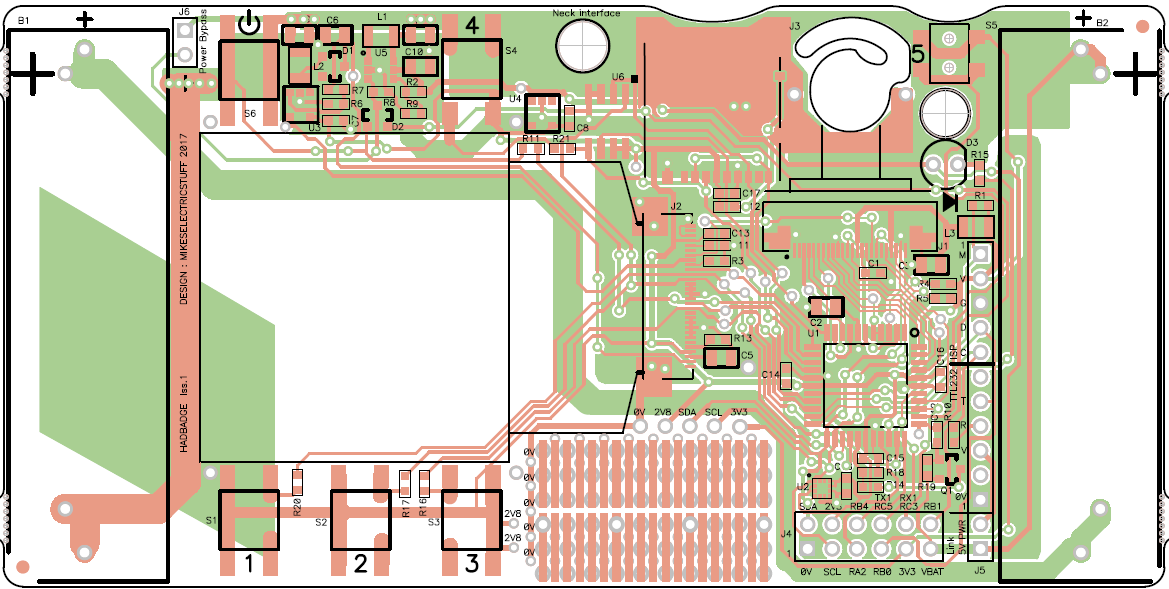
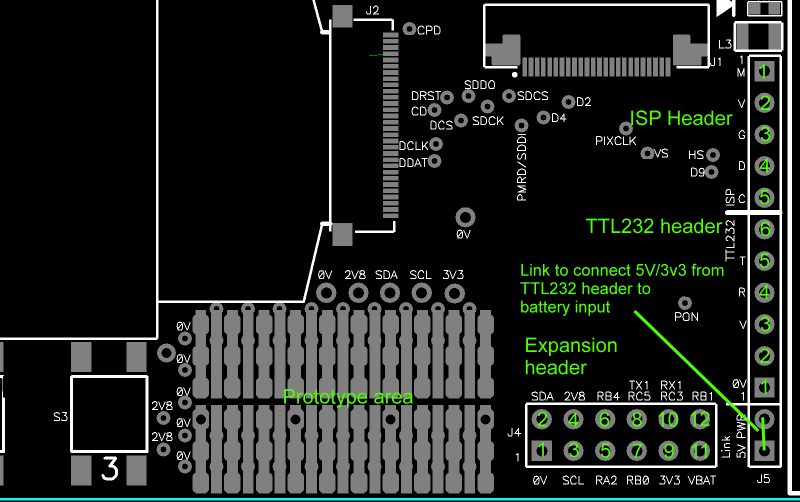
10/11/2017 at 11:04 • 3 commentsExpansion header and hardware test/access points
 DXF of board layout for mechanical dims
PIC32MX1xx datasheetExpansion header pins
Pin Function Comments.
See Datasheet section 11.3 for pin remapping details. Only functions that don't clash with existing badge functionality are listed below. IC - input capture, OC = Output compare (e.g. PWM)1 0V Ground. Also on ISP header pin 3 and TTL232 header pin 1
Also available on several pads around prototype area2 I2C SDA 2.8v levels.
Used onboard by accelerometer and camera
Also available at edge of prototyping area3 I2C SCL 2.8v levels
Used onboard by accelerometer and camera
Also available at edge of prototyping area4 +2.8V Logic supply. Also on ISP header pin 2
Also available at edge of prototyping area5 RA2/RPA2 PIC pin 30. I/O or mappable peripheral RPA2
Set to output by default
RPA2 can be mapped to inputs INT2,T4CK,IC1,IC5,OCFB, and outputs SDO1,SDO2,OC4,OC5,REFCLKO6 RB4/RPB4 PIC Pin 33. I/O or mappable peripheral RB4
Set to output by default.
RPB4 can be mapped to inputs INT4,T2CLK,IC4,REFCLKI and outputs U1TX,OC1,C2OUT7 RB0/RPB0/PGD1/AN2 PIC pin 21. I/O or remappable peripheral
Configured as UART2 TXD by default.
Also on ISP header pin 4 and TTL232 header pin 5
Shared with ISP, so add at least 2K2 in series if driving pin to avoid interfering withe programming functionality.
RPB0 can be mapped to inputs INT1,T5CK,IC2,OCFA and outputs U2TX,OC3,C1OUT
Analogue channel 2 ( need to set ANSELB bit 0)8 RC5/RPC5 PIC pin 38. I/O or remappable peripheral.
5V Tolerant.
Configured as output by default. Reconfigured as UART1 TXD the first time u1txbyte() is called.
Note as this pin is shared with PMA3, it is subject to device errata.
TL;DR : no problems if used as mappable peripheral or input, but to use as output you need to set the corresponding bit in PMAEN and write the output value to PMADDR instead of LATC
RPC5 can be mapped to inputs INT4,T2CK,IC4,REFCKI and outputs U1TX,OC1,C2OUT9 +3.3V Output of 3.3v boost regulator.
Note that if the incoming supply is >3.3v, this pin will rise to the input voltage!10 RC3/RPC3 PIC pin 36
Configured as input with pullup by default. UART1 RXD by default.
Reconfigured as UART1 RXD the first time u1txbyte() is called.
RPC3 can be mapped to inputs INT2,T4CK,IC1,IC5,U1RX,SDI2 and outputs SDO1,SDO2,OC4,OC5,REFCLKO11 VBAT Unswitched battery supply 12 RB1/RPB1/PGC1/AN3 PIC pin 22
Configured as UART2 RXD by default.
Also on ISP header pin 5 and via 2k2 resistor R10 to TTL232 pin 4
Shared with ISP, so add at least 2K2 in series if driving pin to avoid interfering with programming functionality.
RPB1 can be mapped to inputs INT3,T3CK,IC3,U2RX,SDI1 and outputs SDO1,SDO2,OC2,C3OUT.
Analogue channel 3 ( need to set ANSELB bit 1)
Power
Sugested maximum draw from +3.3v or +2.8v is 200mA, maybe 300mA for brief periods.
If the OLED starts dimming, you're pulling too much!
Power may be fed into VBAT if batteries are not fitted, however note that if the supplied voltage exceeds 3.3v, the 3.3v rail will output the incoming supply voltage. This is not a problem for the badge up to about 5V, but be aware of possible dissipation issues in the 2.8v regulator if you are also pulling a lot from 2.8v.
If you have 3.3v -only devices and want to supply from >3.3v ( e.g. lipo), you should use your own 3.3v regulator. You can use the 2.8V rail as an enable to switch your local 3.3v supply if needed.Firmware support for hardware
All I/O used by the badge is intialised in inithardware() in hardware.c
UARTs :
u1txbyte(c) and u2txbyte(c) Send 1 byte to UART1 and UART2 respectively. Baudrates are initialised with values in cambadge.h
UART1 is not mapped to pins at startup, but is mapped, and the UART configured, on the first call to u1txbyte()
A simple receive handler is set up for UART2 - this is in serial.c - see code for more details.I2C :
On-board I2C device addresses : Camera 0x60 Accelerometer 0x3A (8 bit addresses).
The accelerometer is read on every 20mS tick period.
The following routines are provided for I2C access. See globals.h for more info
unsigned int iistart(unsigned char iiadr) Starts I2C command, iiadr - device address ( 8 bit). Returns zero if device does't acknowledge
unsigned int iisend(unsigned char byte) Sends 1 byte, returns zero if no acknowledge
void iirestart(unsigned char iiadr) Send Restart condition for read operationunsigned
int getiic(unsigned int ack) Read 1 byte, ack=1 to acknowledge ( set to 0 for last byte ).
void iistop(void) Send I2C stop conditionAccessing hardware directly
I/O ports :
Set bit 2 on PORTA : LATASET=1<<2
Clear bit 2 on PORTA : LATACLR=1<<2
Invert bit 2 on PORTA : LATAINV=1<<2
Read bit 2 on PORTA : a=PORTAbits.RA2
Set bit 2 on PORTA to input ( output) TRISAbits,TRISA2=1 (0)
Write bit<value> to PORTA bit 2 : LATAbits.LATA2=<value>Some peripheral functions can be mapped to RxP pins - see the "Peripheral Pin Select" section in the PIC datasheet.
e.g. to put Output Compare 4 on RA2 :RPA2Rbits.RPA2R=5; // 5 is OC4 from Table 11-2 in datasheet
To set input capture 1 on RA2 :
IC1Rbits.IC1R=0; // 0 is RA2 from Table 11-1 in datasheet
See hardware.c for more examples.
PIC resources used by badge firmware
Items marked * are used within the main polling loop. Others are only used by applications and may be used by other applications with care if their other functions are not being used.
ADC* : battery read.
Parallel Master Port : Camera.
I2C2* : Camera and accelerometer
Timer 1 : Used for delays via delayus()
Timer 2 : Used by camera and browser applications for frame-rates
Timer 3 : Used by camera capture task to count pixel clocks
Timer 4* : Used for system tick
REFO : Used to clock camera ( do not disable - camera will screw up I2C bus)
SPI1 : Display
SPI2 : SD card and SRAM
UART1 : Can be used for debug output
UART2 : Debug output and serial remote control -
Firmware hacking and adding new applications
10/11/2017 at 11:00 • 0 commentsFirmware APIs
These are not documented here, but in the globals.h include file. This avoids the need to keep this page synchronised with the current firmware version as features are added or modified.
Tools required
Microchip MPLABX (4.0x) and XC32 1.44 (free version). You do NOT (thankfully) need Microchip Harmony.
Although the project compiles using the MPLAB XPRESS online IDE, it does not appear to be possible to download the generated .hex file so it's not useful.If you want to get more serious you will want a PIC programmer such as PicKit 3 or MPLAB ICD3/4, or a 3rd-party programmer that supports the PIC32MX170F256D. When installing MPLABX, if you have a Microchip hardware programmer, also install IPE (MPLABX installer installs it by default), which is used for device programming outside MPLABX - this will be useful for restoring the bootloader.
The firmware is compiled with -01 optimisation, which is the highest available in the free version of XC32. Higher optimisation levels in the paid-for compiler (available as a free trial) may improve speed for compute-heavy tasks ( like particle demo), but things like display and camera grab/save are mostly limited by hardware clock rates etc. so won't see much benefit.Teh compiler flag compiler flag -fno-aggressive-loop-optimizations appears to be needed to avoid some problems seen with -01 optimisation. this is all set up in the project.
There are two MPLABX projects - cambadge and camboot.
See files section for latest version of cambadge project.
Camboot is the bootloader, which you will only need if you want to modify the bootloader.The cambadge project is compiled to a .hex file ( <project path>.cambadge.X\dist\Normal\production\cambadge.X.production.hex) which can then be loaded from the MicroSD card via the bootloader, or programmed directly onto the device via the ISP header using a programmer such as PIckit 3 or MPLAB ICD3/4. (The ICD programmers are significantly faster than Pickit 3 - it may actually be quicker to use the MicroSD card+bootloader method than a Pickit 3!).
For fastest programming speed within MPLABX, be sure to select the MPLABX option "Maintain active connection to hardware tool" in options->embedded.Note that direct programming will overwrite the bootloader! To restore it, you need to program this .hex file which contains the factory-programmed image containing the bootloader and early application code. This can be programmed using MPLABX IPE.
Important note when using a hardware programmer
As the power is soft-switched, when a programmer starts programming the PIC, the power-control line will float, and turn off the power, so programming will fail. To avoid this you need to hold the power button for the duration of programming.
An alternative is to fit the header at J6 (next to the power button), and put a jumper on it. this holds the power always on, avoiding the need to press the button.
The jumper does not affect the use of the power button asn an input. With the jumper fitted, if the badge wants to power down (e.g. timeout) it will sit in a screen showing "awaiting powerdown" and a button to allow a reset.The linker file ( link_forboot.ld ) has been set up to compile to the correct memory locations for use with the bootloader, but also patches a jump into the reset vector, so the same .hex file will run standalone when programmed direct via a device programmer. This avoids the need for seperate standalone and bootloader build variants.
Project Files
apptemplate.c : Demonstration application for use as template for user applications
browser.c : file browser application
cambadge.c : main(), main menu polling loop
camera.c : Camera application
codescan.c : Barcode reader application
display.c : OLED display drivers and display formatting/font stuff
fileformats.c : Routines for parsing, displaying and creating BMP and AVI files
FSIO.C : Microchip MDD file system (with slight hacks for speed)
globals.c : Declarations of global variables
hardware.c : Hardware drivers and initialisation, miscellaneous utility functions
interrupts.c : Interrupt handlers (camera and serial) and interrupt setup
particle.c : Particle demo application
SD-SPI.C : SD card driver for MDD file systems ( with slight hacks fpr speed)
serial.c : Serial remote control
settings.c : Settings applicationappmap.h : mapping of application names for main menu
cambadge.h : includes like xc.h, stdio.h, misc. definitions, build options, display formatting constants etc. must be #included in all source files
camvals_9650.h : camera register intialisation data
font.6x8.h : normal display font data
FSconfg.h : configuration for Microchip MDD file system
FSdefs.h : used by Microchip MDD filesystem
FSIO.h : function prototypes and constants for Microchip MDD file system
genericTypeDefs.h : used by Microchip MDD filesystem
globals.h : function prototypes, extern declarations for global variables, useful macros. #include in all source files
HardwareProfile.h : used by Microchip MDD filesystem
pindefs.h : hardware pin definitions and access macros Only of interest if radically changing hardware.
SD-SPI.h : used by Microchip MDD filesystemlink_forboot.ld : linker script. Edit at your peril!
<path>.cambadge.X\dist\Normal\production\cambadge.X.production.hex : generated .hex file
Adding user applications to the main menu
Each of the applications in the main menu has its own source file. A simple modular application architecture allows user functionality to be added easily to the menu, with no changes to the main source files. To add a new function, you only need to do the following :
- Add a new C source file to the project. This file contains a function char* yourappname(unsigned int action) which implements your functionality. See apptemplate.c for an example.
- Add yourappname to the function list in appmap.h See notes in appmap.h
Your function is called with an action code to tell it what to do. See the template application for more details. Current action codes are listed below. Unknown action codes must be ignored and return 0.
- act_name : Return a string of the application name ( displayed in the main menu) Up to 20 displayed characters
- act_ help : Return a help string, up to 3 lines. Displayed at bottom of menu when application is selected.
- act_init : Called once at startup, used to initalise any new hardware or state that needs to be persistent across application start/stop
- act_start : Called when application is selected from the menu. Typically sets up the screen display, enables hardware etc.
- act_poll : Called from the main polling loop while application is active. Application returns nonzero to indicate it wants to exit back to the menu.
- act_powerdown : Called before the system powers down.
Applications have access to global functions for accessing various hardware functionality, and global variables for status ( e.g. accelerometer values, button states, cursor position etc.) See the file globals.h for details of these.
Your application will receive act_poll requests whenever the menu code isn't doing anything, typically every few microseconds, except when reading teh accelerometer and buttsons, whcih takes typically around 400uS, and occurs every 20mS You should try to keep the execution time for each poll request below 20mS. The only thing that will happen if this is extended significantly is you may miss button-presses that occur while your code is executing. If you really need to sit in a long loop without returning control, you can call readbuttons() to update the button state, but note that unless you call at approx 20mS intervals, auto-repeat timings will be wrong. You can set reptimer to zero in your loop to disable auto-repeat if this is a problem. Note that auto-poweroff will not work if you sit in a loop forever.
Application code for act_poll will typically check the "tick" global to see if it is time to do any timed functionality, respond to buttons, accelerometer etc. "tick" will usually be set to 1 every 20mS, however if application code takes more than the tick period (20mS) to execute, the tick variable will indicate how many tick periods have expired since the last act_poll call. This allows things like timeouts to be kept roughly the same regardless of how long the application takes on an act_poll call simply by adding the tick value to your timer variable instead of just incrementing it. See the demo template application for more details.
If an application depends on the presence of additional hardware, it should if possible detect the presence of the hardware during act_init, and if not present, store this state in a local static variable. Subsequent calls with act_help should include an explanation of what hardware is needed, and calls to act_start and act_poll should return nonzero if the hardware is not present..
Three methods are available for screen access. It is not possible to read back screen data from the OLED display.
- printf() displays text in a 6x8 pixel font, with 10 pixels per line vertical spacing. Various control characters may be included for formatting, including cursor positioning, colour selection, delays etc. These are defined as string constants in cambadge.h, and as C will concatenate string constants, a single printf can contain formatting for positioning the cursor, setting the colours etc.
e.g printf( top butcol "Exit" tabx0 taby2 whi "value:%d",num);
See cambadge.h for all of the available control characters. Globals dispx,dispy hold the current cursor position in pixels. Globals fgcol and bgcol set the foreground and background colours ( RGB565) A macro rgbto16(r,g,b) is available to convert R,G,B to a 16 bit RGB565 value. - Plotting rectangles of solid colour. See plotblock() in globals.h
- Displaying image data from memory to a defineable rectangle in 8,16 or 24bpp formats, with optional Y flip, X sub-sampling and vertical pixel-doubling. See dispimage() in globals.h for more info. In 8bpp mode, a palette is used (global unsigned short palette[256] ) to map the byte values to RGB565, and must be intialised before calling dispimage(), for example using the monopalette() function. Note the palette shares memory with BMP and AVI handling functions. dispimage() can optionally skip pixels in the X axis, to allow previewing of images that are wider than the display.
If you are plotting a lot of pixels, especially small ones, plotlblock() will be rather slow due to the OLED controller command overhead of each operation. You will find it MUCH faster to build the image in a memory buffer and then display it using dispimage().
There is variant of plotblock(), mplotblock(), which plots to a memory buffer, for later display by dispimage(). See particle.c for an example of usage.Printf() output can be redirected to UART1 or UART2 by setting the global dispuart to 1 or 2 respectively, and 0 to return to normal display output. Setting bit 4 of dispuart outputs to both the screen and the selected serial port.
Buttons are detected by looking at the butstate and butpress global variables. Bits (but1..but5,powerbut, defined in cambadge.h) in butstate reflect the realtime state of the buttons, which are read on each 20mS tick event. Bits in the butpress variable are set once when a button is pressed, i.e. you will see the bit set on exactly one act_poll call to your application code, and this call will coincide with a tick event. If button reads in loops outside the main polling loop are needed, readbuttons() can be called to update the button states. Note that readbuttons() assumes it;s being called at the 20mS tick period for purposes of auto-repeating.
The accelerometer is read on each 20ms tick event, the results being stored in globals signed int accx,accy,accz The range is approximately -17000 to +17000. Note that the zero position and span will vary slightly from device to device, and with temperature.
Using the camera
The camera is initially enabled using cam_enable(), specifying a mode number which sets the basic capture parameters. See cambadge.h for details of available modes).This powers up and initialises the camera module, sets up default capture parameters.
Capture may then be started using cam_grabenable()
cam_enable(0) disables the camera and puts it into low-power standby mode,After setting up the basic mode using cam_enable, capture parameters may be changed via the following global variables:
xpixels,ypixels: number of pixels captured in each direction
xstart,ystart : Position of first pixel within camera image to capture. These can be used to pan around the camera image.
xdiv,ydiv : divisor for captured pixels, e.g. 2 captures every other pixel, 4 captures every 4th etc. These will generally work as expected in mono mode, but there are other constraints on xdiv in colour modes, which are limited by DMA bandwidth. xdiv must be >=2,
Invalid combinations of parameters can cause wierd things to happen.
See the description of cam_enable and cam_grabenable in globals.h for more info.
Do not change settings while grabbing is enabled, as a vsync interrupt may start capture in between changing different variables, as a capture may start with a mix of old and new parameters.Global variables are available for the application code to determine the current capture state:
cam_started - set when active part of frame starts capturing ( cleared by user code)
cam_done - set when a frame has been captured ( cleared by user code, or cam_grabenable)
cam_busy - camera is still in the process of capturing a frame. Set on Vsync, cleared when all lines are captured
cam_line - last line that was capturedPIC resources available to user code
RAM : Applications should not use malloc! A large buffer is declared globally, and is available for use by application code. This is declared as a union of chars, shorts and longs, and so may be used for arrays of any of these types within application code. A seperate 1024 byte buffer is also available, again defined as a union of chars,shorts and longs.
See globals.h for more details of available memory and methods to share user array types with the global image buffer.
Nonvolatile memory : The flash memory 0x1D00 7C00 to 0x1D00 7FFF is reserved for nonvoltile storage. This will not be overwritten by the bootloader or direct programming. It is sized to be one erase page (1K), as a whole page must be erased to chnage values.
The firmware includes two functions to support this ; nvm_read() and nvm_write(). these read and write the whole 1K NVM area to global RAM buffer nvmbuf[]. This is a union that can be accessed as bytes, shorts or words :
nvmbuf.bytes[0..nvm_size]
nvmbuf.shorts[0..nvm_size/2]
nvmbuf.words[0..nvm_size/4]To use NVM, use nvm_read() and copy your data from nvmbuf. To update, do nvm_read(), update your values in nvmbuf, then nvm_write(); nvmbuffer is overlayed with avibuf and pallette, so must not be relied on for long-term storage.
NVM will not be overwritten when loading new hex files via the the bootloader, but it will be erased to 0xffffffff if directly programming via a hardware programmer. There appears to be an option in MPLABX program dialogue to make it preserve ranges by reading and then rewriting, but I have yet to get this to actually work correctly.
NVM allocation : NVM byte addresses 0300-0x3ff within the NVM space are reserved for internal use. If you want to use NVM for a new application, please add the address range you use in the comments for this page, and check the page for existing allocations. Allocations should be in multiples of 4 bytes, and word aligned.
The PIC clock frequency is 48MHz - this is chosen to get nice baudrate divisors for high baudrates (1,2,3,4,6Mbaud). Parameters like tick frequency and baudrate use the clockfreq #define to adjust to different rates.
PIC peripherals used by badge firmware
Items marked * are used within the main polling loop. Others are only used by applications and may be used by other applications with care if their other functions are not being used.
ADC* : battery read.
Parallel Master Port : Camera. I2C2* : Camera and accelerometer
Timer 1 : Used for delays via delayus()
Timer 2 : Used by camera and browser applications for frame-rates
Timer 3 : Used by camera capture task to count pixel clocks
Timer 4* : Used for system tick
REFO : Used to clock camera ( do not disable - camera will screw up I2C bus)
SPI1 : Display
SPI2 : SD card and SRAM
UART1 : Can be used for debug output
UART2 : Debug output and serial remote controlIf you use a timer in an application, set it up on the act_start call, not act_init as other applications may have changed it before yours runs.
Timer 3 is used by the camera, and is configured by cam_enable, so can be used by other applications.The ADC is used to measure battery voltage on a tick event. It may be used by application code by using claimadc(1) to disable battery reads, and claimadc(0) when done to reconfigure it for battery reads. When claimed, battery voltage will read a dummy value of 4000mV.
UART2 is used by serial control and may be set up to output debug data.
UART1 is free for use, and by default is routed to the expansion header and the peripheral selects mapped to these header pins. initial baudrates for both UARTS are defined in cambadge.h
Printf() output can be redirected to UART1 or UART2 by setting the global dispuart to 1 or 2 respectively, and 0 to return to normal output.At startup, UART1 is not enabled, and the RC3/RC5 pins configured as input ( with pullup) and output ( defaulting high0 respectively. the first time u1txbyte is called, the UART will be enabled, and the pins configured for UART operation.
See interrupts.c for current interrupt usage. DMA channels 1 to 3 are unused.
Serial control
Some simple serial control functionality is included, accessed via a TTL232 cable plugged into the TTL232 header. This is primarily intended for debugging, for example messing with camera parameters, debug text output, pulling out camera data etc. A 3.3v TTL cable should be used. There is a 2k2 series resistor in RXD so a 5v cable will probably not cause damage, but the 2.8v logic levels may be marginal for transmitted data to a 5V input.
As this interface is mostly there for debugging , it is subject to frequent changes and it is not documented here. See the serial.c source file for details.
Blue screen of death
An general exception handler is provided to catch memory errors and div by zero - this displays "BSOD" in inverse blue and then the watchdog will cause a reset a couple of seconds later.
- Add a new C source file to the project. This file contains a function char* yourappname(unsigned int action) which implements your functionality. See apptemplate.c for an example.
-
Bootloader
10/11/2017 at 10:59 • 0 commentsBootloader
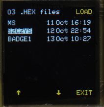
A bootloader is included which allows firmware programming from .hex files from the SD card.

At startup, the bootloader first verifies a checksum on the application area, and if valid, enters the application code after approx 1 second. Pressing the bottom-left button during this period (or holding it when turning on) allows manual entry to the bootloader menu If the application checksum is invalid, it displays a warning message and allows the user to enter the bootloader menu or attempt to run the application code anyway (the latter will usually fail). The checksum is created by the bootloader when it has finished programming the flash, ensuring that a failed or incomplete programming operation will not result in a valid sum.
The bootloader uses the PIC user ID config locations in the hex file to verify that the code is intended for the badge hardware. A warning will be displayed if there is a mismatch. Any addresses in the hex file outside the application area will be ignored.While the bootloader is active, the LED will blink periodically. This is mostly to indicate that the bootloader is running, in the case of a faulty display, to distinguish from lack of power etc.
The bootloader will power down after 2 minutes of inactivity.
Flash memory usage
0x1D00 0000 to 0x1D00 7BFF : Bootloader
0x1D00 7C00 to 0x1D00 7FFF : Reserved for application nonvolatile settings.
0x1D00 8000 to 0x1D03 FFFB : Application code
0x1D03 FFFC to 0x1D03 FFFF : Checksum on application code. 32-bit sum of all bytes in application area, LSByte first
0x1FC0 0000 to 1FC0 0BEF : Reset vector and boot area (part of bootloader)See files section for bootloader MPLABX project and combined bootloader+application code .hex file
Camera badge for Supercon 2017
Conference badge for the 2017 Hackaday Superconference Features: camera module, 128x128 OLED display, MicroSD card socket and accelerometer
