 Nikos
Nikos-
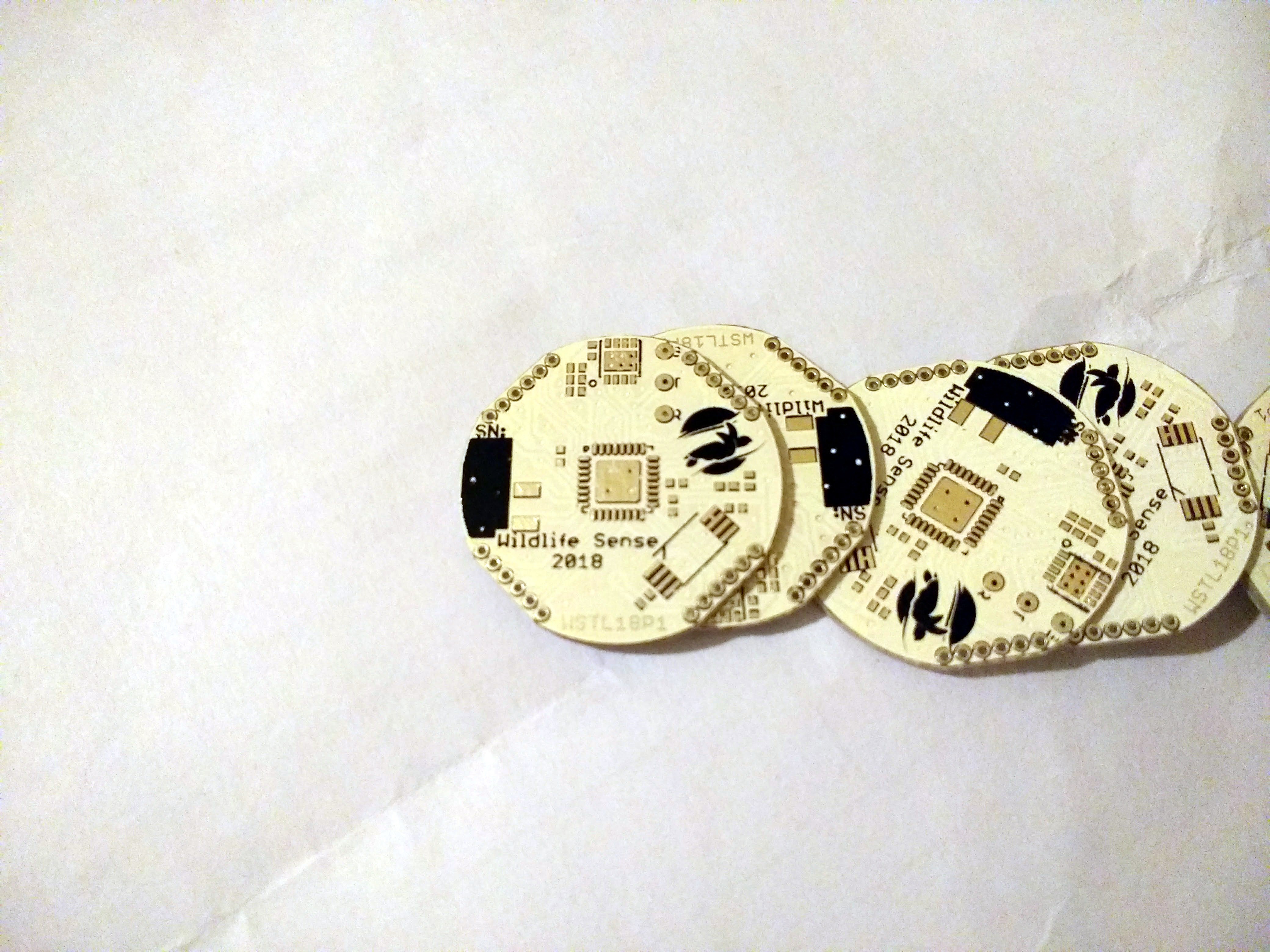
First PCBs and cases arrived
11/20/2017 at 22:43 • 5 commentsMy first prototype PCBs have arrived!
![]()
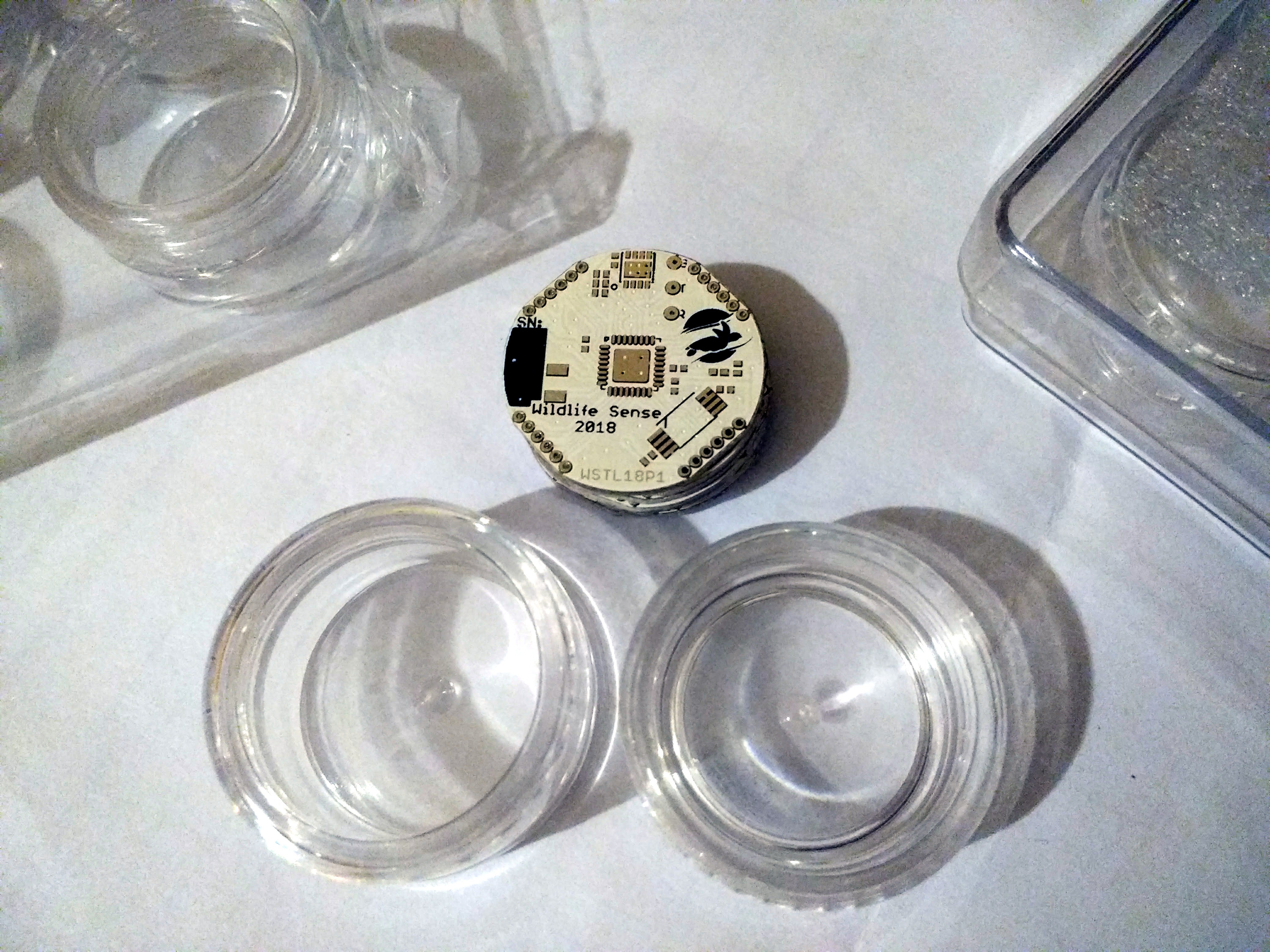
My first concern with the PCBs was to see which case they would fit in. And by case I mean acrylic cosmetic lotion jar, like the ones you can see below.
![]()
The distributor's website only listed their internal volume (Left 5ml, right 3ml) and their external diameter, so I had to calculate the internal diameter by counting pixel on available photos and intrapolating from the external diameter. I also had to guess a margin because these jars tend to get narrower towards the bottom.
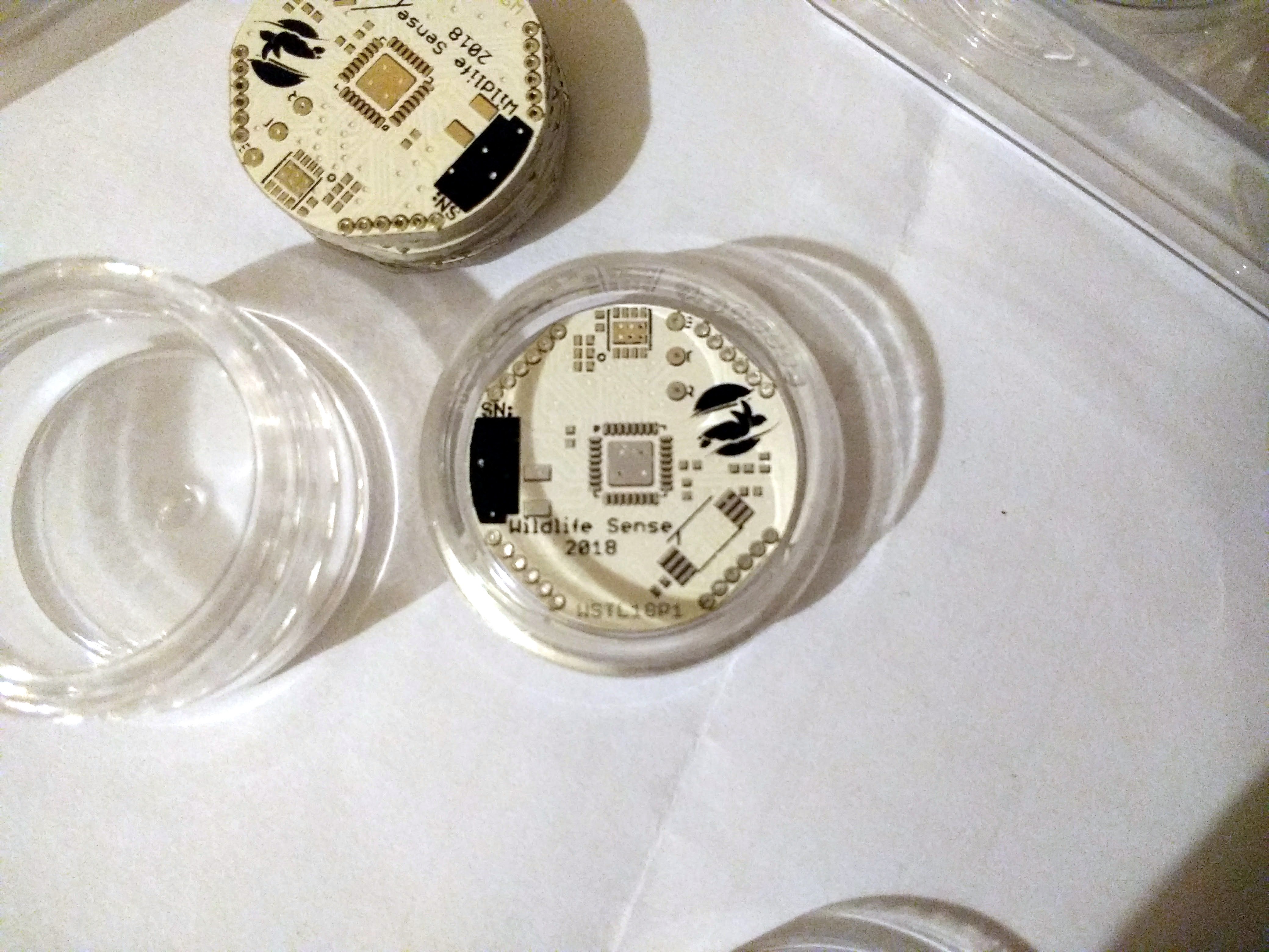
The 5ml jars are only a couple mm wider than the 3ml ones, but they are considerably taller so I'd prefer the PCB to fit in the 3ml jar. And it did.
![]()
It fits so well that it can't move at the bottom. Once the battery holder is soldered on the underside of the board, there should be half a mm or so of marginal space.
I like these jars because of their very low cost (€0.35 for the 3ml ones, €0.21 for the 5ml ones) but also for their ease of use - just a screw-cap to open/close them. No screwdriver. However, they are certainly not waterproof, and I need them to be.
Since these temperature loggers are going to be inserted in the sand and left there for anywhere between two and six months, regular opening won't be required. To keep costs low, I'd prefer to add a small amount of food-grade silicone (so no contamination will be caused to the environment) on the thread before screwing the cap on. After the data logger is retrieved, the seal can be easily broken open and discarded. The loggers will have to wait for at least 12 hours for the sealant to cure before deployment. Luckily, deferred start of logging should be an easy feature to implement.
Next I plan to hot-plate solder a couple of boards and begin programming them, but also to perform some testing on the sealing process mentioned above and the results in water-tightness.
-
Checking out the battery holder
11/02/2017 at 19:55 • 0 comments![]()
Last weekend, I ordered parts for the first prototype from Mouser and PCBs from Seed Studio. I also ordered a stencil for the top side from OSH Stencils. The parts arrived first, and while waiting for the boards I made a print-out to verify the battery holder fits well on the circuit board.
I opted to use a CR2032 battery because it's a good combination of size, capacity, and low-cost availability. The BAT-HLD-001 holder by Linx offers smallest footprint and by far the lowest price between holders for this battery. I've placed it on the bottom side of the board, so I'll have to assemble the device's top side first and then solder the battery holder on the bottom.
The battery holder attaches to the board with SMD pads, but on the next prototype I'll use its available through-hole version (Linx BAT-HLD-001-THM). That one will be easier to hand-solder, will allow slightly smaller board size, and will have a stronger hold on the board, which can help since the device will be handled during battery change and data transmission.
The battery holder is the largest part by far and alone defines the size of the board. All other parts can easily fit on the other side of the board.
![]()
The next smaller available battery that's between 2.7V and 3.3V is the CR1632 at 140mAh, which isn't bad and saves 4mm. But changing to this battery would have a few drawbacks: the cheapest battery holder for that size is €0.30 more expensive than for the CR2032 and batteries aren't cheaper. You also can't find a CR1632 at a corner store, but you can find a CR2032 almost everywhere.
Most importantly, I currently don't have a reason to switch to a smaller battery because the CR2032 will fit in the dirt-cheap case I've selected, and a smaller size of that type of case isn't available. I'll discuss the case in my next post.
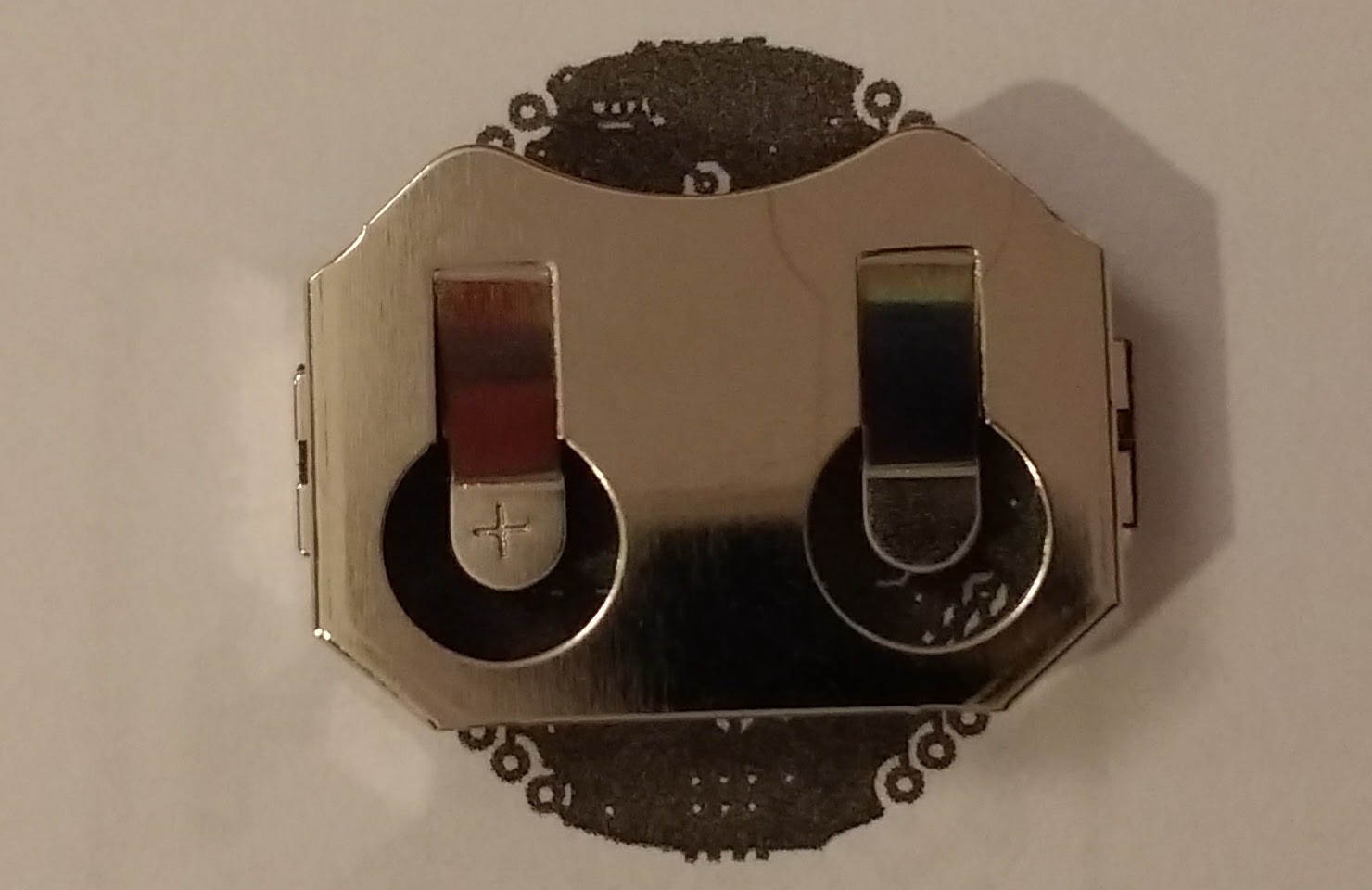
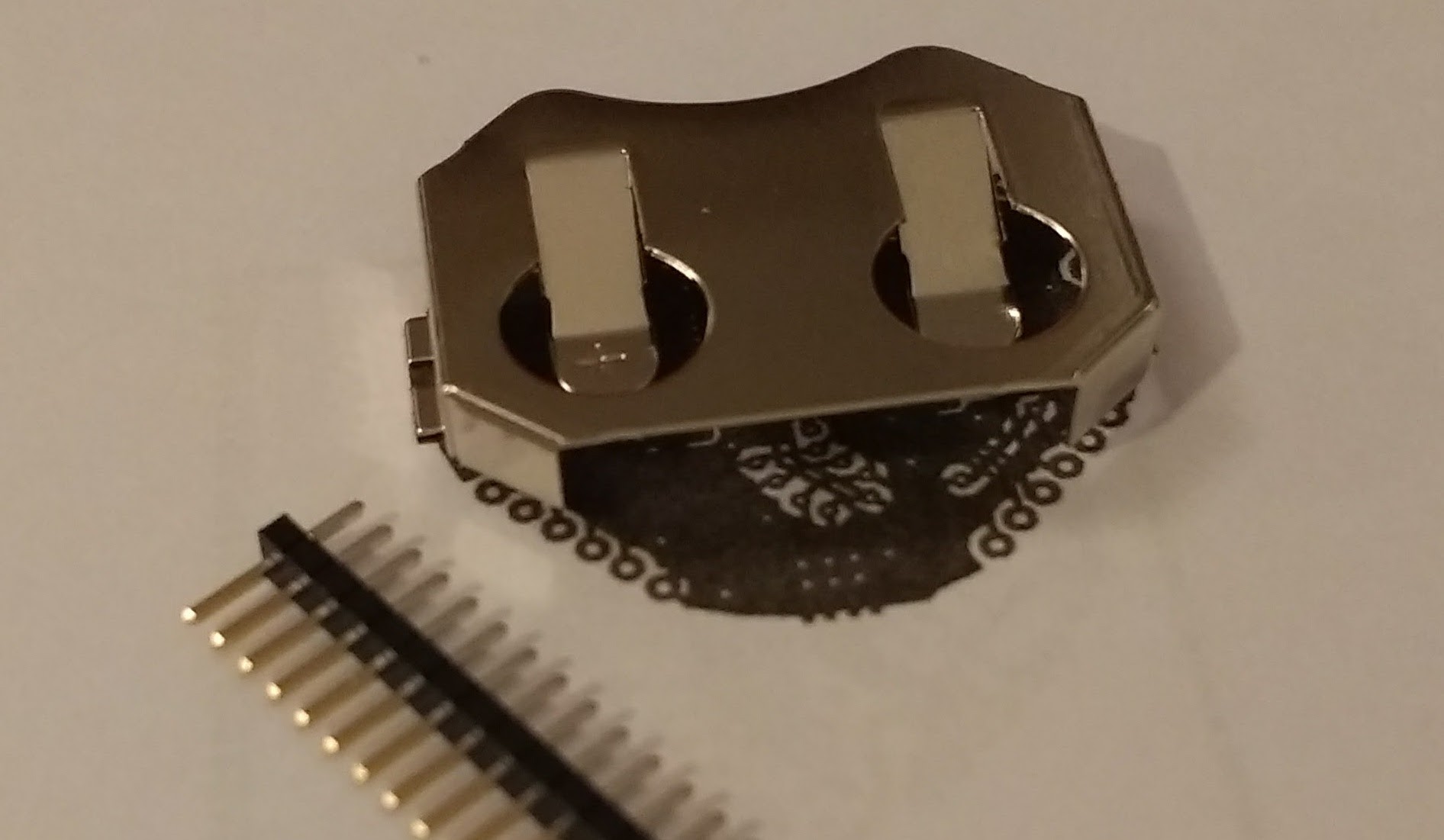
A final word on this battery holder and my design: In my previous post I discussed making 14 MCU pins available near the edges of the board. I had to use 1.27mm (0.05") pitch holes, but at the time I didn't think that the battery holder would be right over the holes.
![]()
This only occurs on one side, as the other side of the holder is open for battery insertion. I've included the 1.27mm (0.05") header here to show that if it was inserted in the holes it would touch the holder, which is the positive battery pole.
On the other side, the headers wouldn't touch the holder but the battery would touch them while inserted or removed. To solve this problem, one can do one of the following:
- Don't use the pins, this is a temperature logger, not a development board. This will apply to most cases.
- Clip the header's underside after soldering and before placing the battery holder.
- Don't insert the headers all the way in. Keep them flush with the underside. This is probably the best solution.
- Don't use headers. Insert any cables directly into the pcb and solder carefully. Limits reuse.
- On the side seen above, bend the battery holder's flap. Will make battery placement a little tricky but won't solve the problem of contact during battery insertion/removal.
- Use a really thick PCB. Those are really expensive. Not a serious solution.
Also, in the rare case you will use this as a development board, use female headers, not male as seen here.
-
14 unused MCU pins made accessible
10/28/2017 at 12:22 • 2 commentsA handful MCU pins are enough to implement a temperature logger; Two connect to the sensor via I2C and one more for the interrupt option, four for SPI to connect to the memory chip, two for UART to extract stored data, change settings, user firmware update etc, one for the reset pin for in-system programming (plus SPI), and one for a blinking LED. Add two for the real time crystal and all the power pins and on the 328PB this leaves 14 pins unused.
![]()
Before: 14 pins were left unused.
I could go for a lower-count MCU but the only AVR that fits all requirements is the Tiny417/817. This is a new chip and uses some different concepts, which would mean a steep learning curve. While this is an option for future models, I don't have time for it at the moment as I need to produce 50 and program them for deployment by next summer in my spare time.
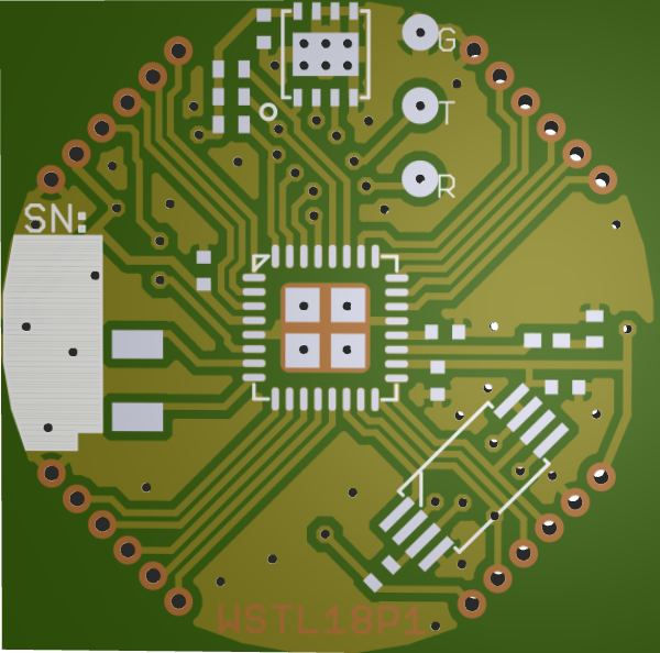
This leaves me with 14 unused pins, so I opted for making those accessible. I had to redesign the layout to make way for all these lines but, at no cost difference, this temperature logger can now double as a coin-cell powered development board.
![]()
After: All MCU pins are used or accessible via 0.05" headers.
-
A very quick look at power consumption
10/08/2017 at 22:27 • 0 commentsThis project requires ultra low power consumption while sleeping, and it won't have the option to switch off either the temperature sensor or the memory chip through their voltage regulator, as all devices will be powered directly by the 3V battery.
The MCU's power consumption while on power-save with a Real Time Counter running is 1.3uA, and the MAX30205 shutdown-mode power consumption at 3.0V and around 30°C is 1.62uA. The memory chip consumes 350nA on deep power down mode. This brings the total power consumption to 3.22uA while inactive. On a CR2032, which usually has over 200mA capacity, this logger could, in theory, sleep for over seven years.
Of course I'll have to consider the high consumption for the few milliseconds it takes for the chips to wake up, sense and store temperature, and go back to sleep, and also the battery's self-discharge. But I'm fairly confident that even with bulk-purchased coin cells, which often have a lower capacity, the target of 180 days is achievable.
-
Selecting memory chip
10/08/2017 at 22:01 • 0 commentsThe temperature sensor I chose for this logger (MAX30205) outputs sensed temperature in two bytes. Those are in two's complement format, with each LSB representing 0.00390625°C. Instead of transforming the data to temperature, I believe it's best to store the original two bytes and do the transformation after retrieving the data.
According to the project's requirements, I need to sense temperature every 10 minutes and store it for 180 days. This comes to a total of 6*24*180=25920 records or 51840 bytes. Memory chip capacity is always listed in bits, so the requirement is for 414720bits or 405kbits.
The logger can use either SPI or I2C to communicate with the memory chip, but SPI would make PCB routing easier as on the Atmega328PB the SPI pins are opposite the I2C pins, which is how I'd like the chips to be arranged.
Back on mouser.com, I select the "Memory" category and select all capacities larger than 405kbits. Oddly, there's a 440kbits entry but that's for a configuration memory family and it isn't cheap, so I don't include it and go straight for 512kbit and larger.
Once this filter is applied, I order the results on the pricing column. The first listing is a 512kbit SPI chip from Adesto at €0.272. That's a SOIC8 chip, which is not very small and may be problematic for a tiny logger. Three entries down I see the same device in a TSSOP8 package, which is roughly half the size. That's small enough and easy to route for a two-layer prototype PCB, and it's priced at €0.315, only four cents over the cheapest option.
This is a great memory chip, easy to use and program for, and the memory can be written to byte by byte, which is perfect for low-power logging of two bytes every 10 minutes. With a 350nA power-down mode, it also fulfils the project's ultra low power requirement.
-
Selection of temperature sensor
10/03/2017 at 14:22 • 0 commentsThis project will use a digital temperature sensor to avoid analog circuitry and keep cost per unit and size as small as possible. I tend to use Mouser to source parts because they're one of a few that ship to Greece with no hassle.
I'm looking at "board mount temperature sensors" and the first category I'm going to filter on is "accuracy". I selected all accuracies up to +/-0.125C. The next choice after that is 0.2C, which is too large for this project's goals.
Only 6 temperature sensors are left. The cheapest one is Maxim's MAX30205MTA+ at €1.53 for one. The next one is Silicon Labs' SI7051-A20-IM at €2.02 for one. The rest are either too expensive or not accurate enough, so I'll just compare these two.
For a quantity of 50, MAX30205 is €1.41 and SI7051 is €1.79 so the cost difference (€0.38) would be €19 for a batch of 50. Not negligible but I'll have to have a closer look at how both fit the requirements.
Both are rather small 3x3mm sensors that are controlled via I2C. Their stated 0.1°C is only valid between 37°C and 39°C for MAX30205 and 35.8°C to 41 °C for SI7051. I'm interested in accuracy between 26°C and 34°C, the temperature range in which sea turtle eggs incubate. Over this range, stated accuracies are ±0.3°C (+15°C to +35.8°C) for MAX30205 and ±0.13°C (20.0°C to 70.0°C) for SI7051. TheSI7051 seems to retain high accuracy over a wider range, including my range of interest (26°C to 34°C).
Page 5 of the MAX30205 datasheet includes a plot of accuracy vs temperature on various voltages. This is very useful information, as it shows that for supply voltage of 3.0V accuracy remains better than ±0.1°C between 20°C and 50°C. This detailed information is not available for the SI7051, which is a drawback if any research results end up in a scientific publication.
")
The MAX30205 operates between 0°C and 50°C, while the SI7051 operates from -40°C and +125°C. While both are wider than my range of interest, it would be nice to have some extra range, perhaps up to 70°C, so I can measure sand temperature near the sizzling beach surface during hot summer days. However this is not a core requirement.
Based on the project's requirements, MAX30205 features the lowest cost and fits the accuracy and reliability needed, so this is the temperature sensor I'm choosing for this project. The SI7051 can remain an alternative if an extended temperature range is required.
Low-cost/power/size temperature logger
A low cost ultra-low-power small-sized high accuracy temperature logger for use in scientific research.


")