-
Final product design outline
09/28/2014 at 04:15 • 0 commentsThe goal of my project is to provide a system that consists of a docking cone with wires that your batteries including their respective balance leads will be connected to that mounts to the bottom of multirotors. Inside the cone there will be a wide angle webcam, sonar and a single board computer. Onboard computer connects to a flight controller over UART using mavlink packets and it is expected that the flight controller is using the arducopter firmware version 3.1 rc7 (or a version that has sonar support for your chosen flight controller).
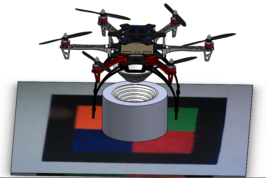
(Prototype rendering of the system)
Currently I am designing it for the F550 frame from hobbyking which is a knock off of the DJI H550 frame with a set of tall springy landing skids (they are useful for rough landings and have saved my hex a few times) ,but the design can be easily adjusted to fit other frames by changing the parameters(height, width, angle and spacing of connection rings) of the docking cones.
The system may not be suitable for small multirotors as it weighs approximately 500g, but this weight could be reduced in later versions as I am not optimizing for weight due to tight time constraints and prototyping.Integration with arducopter
At a later date when the project is more mature I am going to make further modifications to the arducopter software to add in configurations to allow easier external control and integrate my offboard controller more into the firmware to allow easier integration for people who want to use this system.
-
Current testing progress and results!
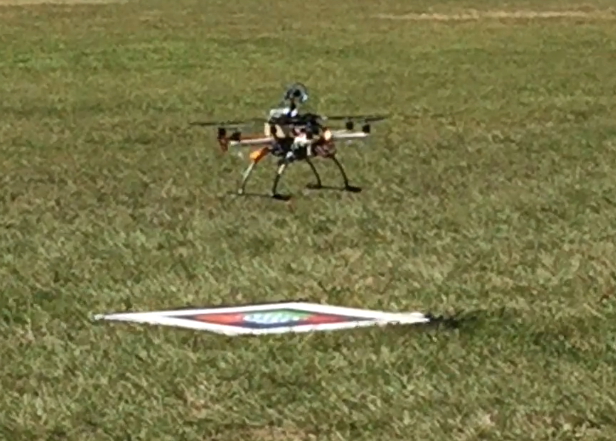
09/28/2014 at 04:13 • 0 commentsAs part of my testing a rig has been set up in the front yard involving a rope between the roof and a tree in the yard which allowed me to test the copter repeatedly and ensure that any changes I made don't destabilize the craft or cause fly aways. Once the software has been proven to not cause problems and the copter had managed to perform its task while tethered a few untethered flights were performed in a reserve far away from people, power lines and buildings.
It has been a slow and long process ,but finally I have managed to achieve a set of results that can be considered a working prototype system. The copter has been able to reliably detect and center itself over the target them bring itself down onto the target with a 10cm error outdoors which should be fine as the docking station is being designed to deal with that much error. Currently the system is a little slow with actuating itself over the target but this is past of slowly building up confidence in the system and taking it slow for safety reasons both for the copter and myself.Possible improvements:
I can also improve my results when I switch over to a better state estimation when I can finish off the EKF design and I think velocity based control for the positional control will work better than attitude based. As well as implementing a sliding mode controller rather than cascaded PID loops -
Prototype docking station design
09/28/2014 at 04:04 • 0 commentsIn order to achieve the task of docking a multirotor for recharging a custom docking station had to be designed. Several designs were considered against the requirements in order to select the most appropriate.
Requirements
- Shall allow a +- 5cm tolerance on landing
- Shall be able to connect to at least a single lipo(4s) and the corresponding balance
connections– Therefore be capable of 2 + 5 connections(power and balance) to 4+10 connections (for 2 4s lipos in parallel)
- Should be capable of allowing a +- 15 deg orientation misalignment
- Should allow a range of multirotor sizes and configurations
Mechanical battery swap
For this design the copter lands and a mechanism removes the battery from the copter and then switches in a fresh one from a cartridge
Mechanical gantry for alignment
For this design the copter lands on the target in the approximate area then an arm sweeps it to an appropriate position.
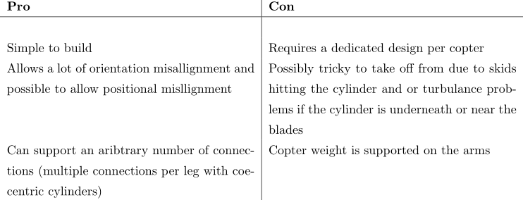
Big cylinder with notches
For this design the copter has contacts on the arms and lands into a cylinder with triangular notches to guide it into a resting position
Guiding cones
This system is based off satellite style docking mechanisms with one side active and the other passive. The cone system fits over the camera and sonar assembly at the base of the copter and a cylinder with a raised section and a mating cone is placed on the landing target in such a way that the docking is complete when the landing skids barely touch the target.
Arbitrary contact grid
This system is based off the idea of having metal contacts placed on the landing skids and a landing on a target with a number of contacts in a pattern that maximize misalignment -
Visiual detection of landing target
09/28/2014 at 03:46 • 0 commentsVision can be a very complex problem and when you add in the requirements and restrictions from the multirotor it can be very hard to find a suitable algorithm.
- Requirements of system
- Capable of dealing with outdoor conditions during the day
- Global and local illumination changes
- Due to clouds, shadows (both copter and objects), changes in time of day and so on. This can really ruin color based approaches if they have assumptions about the background(which they tend to do)
- High amounts of IR
- The sun is a big ole ball of IR so IR based approaches don't tend to work during the day without some heavy assumptions or very powerful IR leds
- Cluttered environment
- In order to remove any assumptions about the operating environment. Which can make model based searches fail if similar objects exist in the scene
- Arbitrary backgrounds
- Once again to remove operating assumptions this means that color based approaches can fail if they have assumptions about the background (which they tend to do)
- Capable of dealing with the operating conditions of a multirotor UAV
- Partial occlusion
- Due to the pitching and rolling movement of the copter in order to translate it can cause the image to partially move out of the image.
- Heavy skew
- As above but it causes skew
- Blur
- Depending on a large number of factors such as exposure, sensor quality, vibrations and speed of movement there can be some blurring in the image
- High variability in scale
- The vision system has to be capable of dealing with the copter at as many heights possible from 20cm to 20m away
- Arbitrary changes in orientation
- The camera and copter can be orientated arbitrarly compared to the target so the system has to be capable of dealing with that.
- Needs to operate as quickly as possible as to run in realtime (5hz minimum)
- If its too slow the control will not be capable of dealing with perturbations and compensate for error
- Limited processing power
- Due to the time constraints and onboard computer expensive visual operations are not suitable
- Needs a high detection rate and low false detection rate
- Cant have the copter trying to land somewhere that’s not the target
- Needs a way of determining the confidence of the detection
- This is useful for use in data fusion such as a Kalman filter and determining if there are false detections.
Approaches tried and some results / notes
- Approaches tried
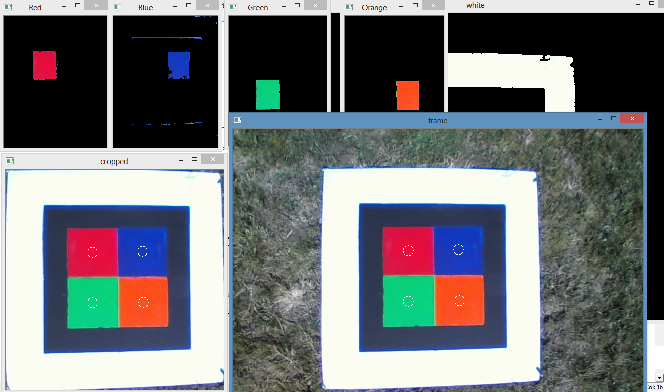
- Color blob detection of the centers and using the color to solve the correspondence problem and PNP for pose estimation
- Color blob detection with cropping(based on looking for the white outline) and PNP for pose estimation
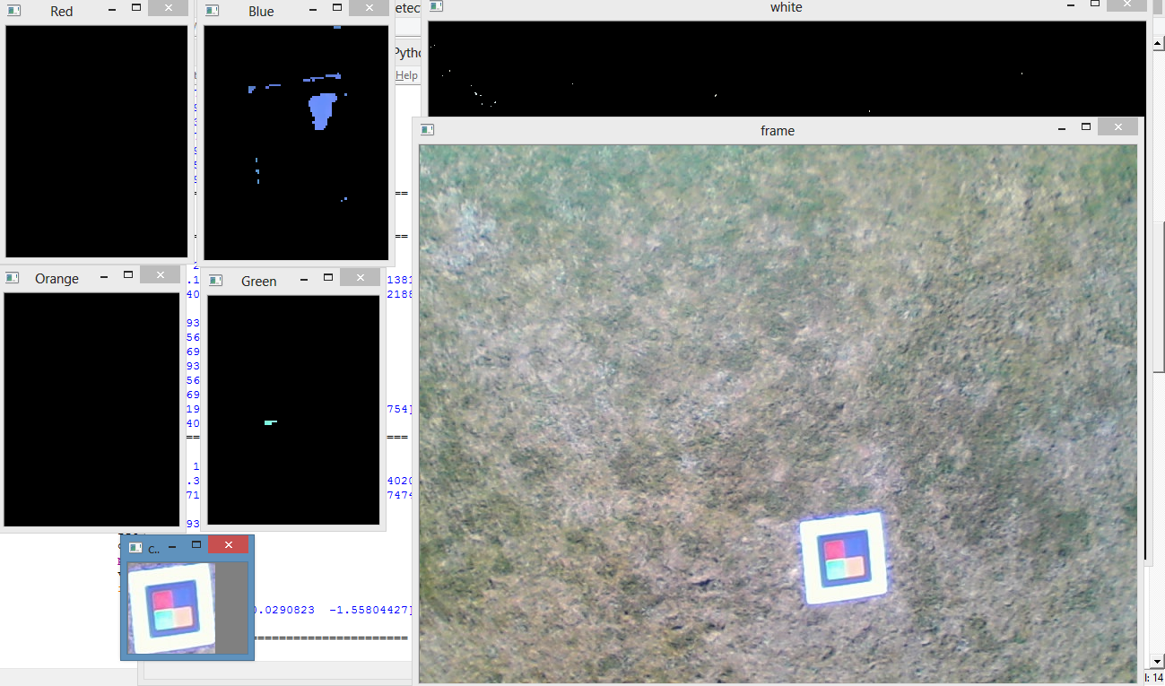
These approaches worked at about 3 hz or 15 hz with the cropping approach and most of the image is cropped out ,but PNP is very sensitive to pixel coordinates of the detected colours. Also colour based approaches are sensitive to changes in illumination and this approach doesnt allow any occlusion of the target.
Example of working blob detection (circles are detected centers)
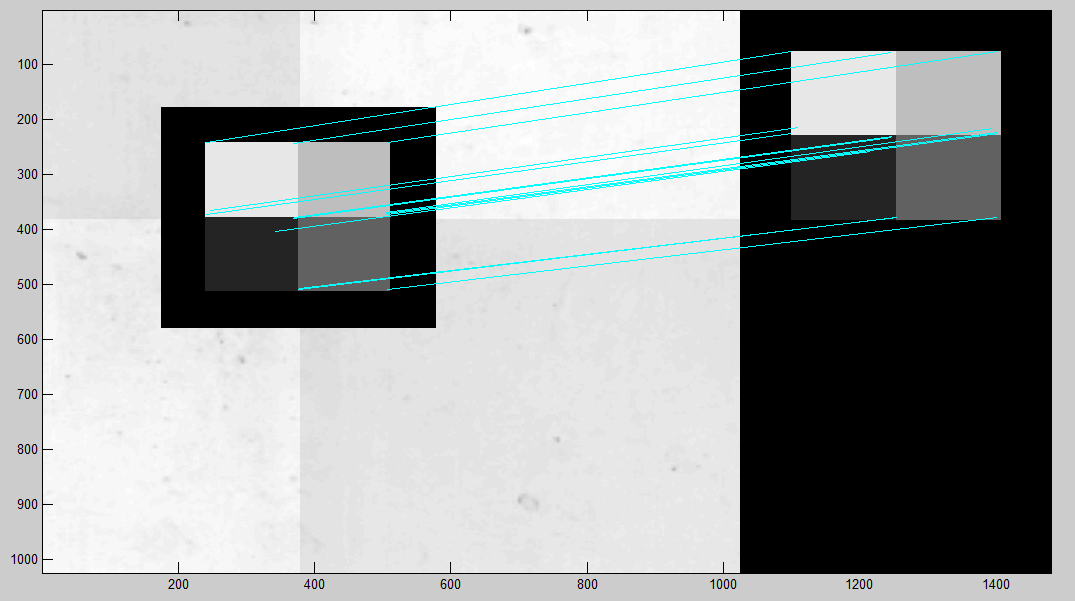
Example of breakdown of blob detection- SIFT / SURF / BRIEF / ORB based template search using RANSAC and RPP
Example working output of image feature based approach
Example breaking down output of image feature based approach
- CMT
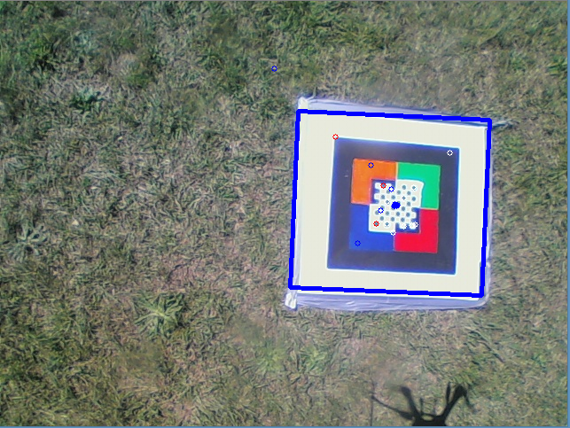
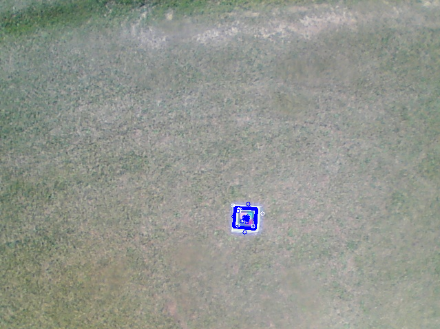
Consensus-based Matching and Tracking of Keypoints (CMT) is a new algorithm from a conference this year it works by tracking image features or keypoints between frames and comparing keypoints based on their descriptors. For CMT I altered the landing target to have a checkerboard in the center which gives a higher number of key points to detect at lower heights.Examples of CMT working at 2 meters and 15 meters above the ground from the copters downward facing camera. The blue squares are the detected markers and the dots are the matched keypoints.
Output from CMT outdoors with hexacopter 2m above ground
Output from CMT outdoors with hexacopter 15 meters above the ground -
Simulation of autonomous landing
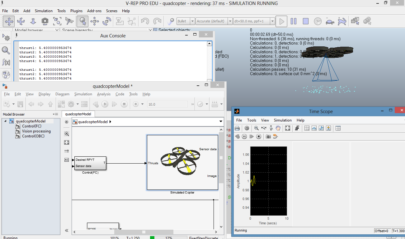
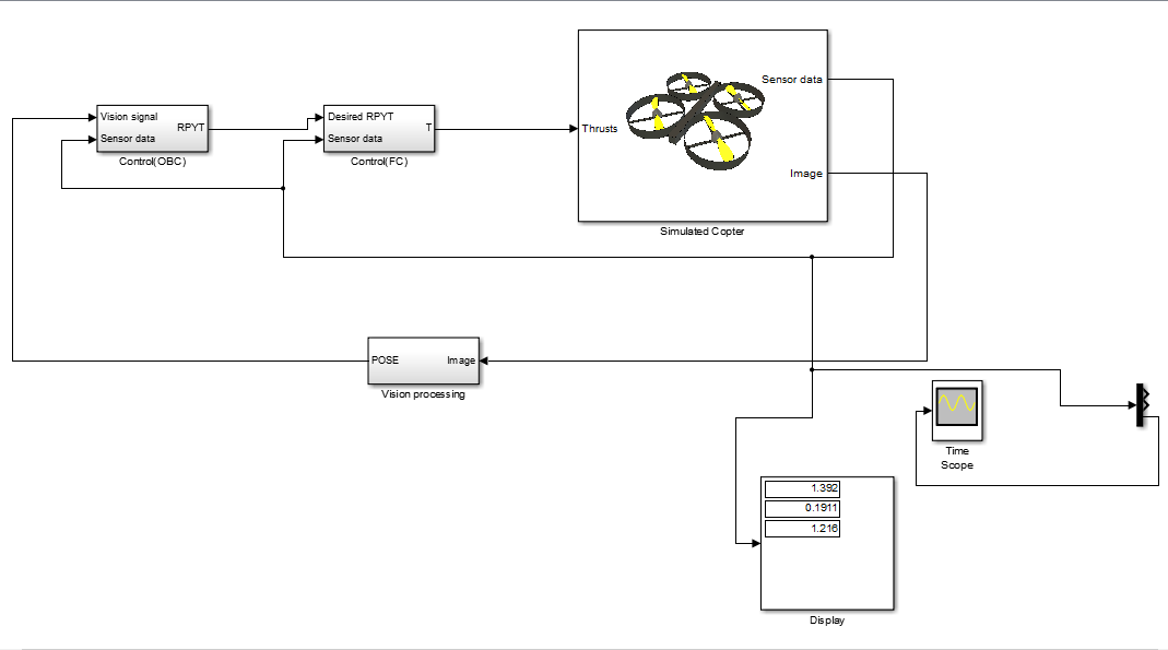
08/21/2014 at 02:23 • 0 commentsUsing the free vrep simulation environment and my access to matlab and simulink via the university the simulation model of the copter has been developed and I can work on designing vision based control algorithms without the risk of crashing copters.
-
Flight tests of autonomous platform
08/21/2014 at 02:07 • 0 commentsThe autonomous platform was assembled based on the design documents and all the electronics were validated in the lab. Once the system was confirmed to be working the platform was taken out to the ACFR test area on the Marulan farm.
A number of tests were performed and the pixhawk running the arducopter firmware performed as expected.
Preliminary testing of the visual system was started ,but the software integration requires more work and the addition of more failsafes to deal with fail cases
-
Selection of onboard computer and autopilot
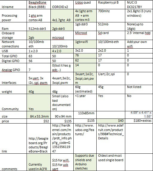
08/21/2014 at 02:04 • 0 commentsAfter considering the options avalible the three best possible solutions which are very close are the udoo, odroidx2 and the BBB.
The odroidx2 is the most powerful processing unit by far it is almost twice as powerful as the udoo and almost 7 times as powerful as the BBB (assuming that all the cores are fully utilised) it also has twice and four times the offering of ram as the others.
The downsides of the odroidx2 is that it does not have tha ardunio envrionment avalible on the udoo but since the FC(pixhawk) is receiving the sensor data it does not need many gpio pins itself. Also the selected sonar sensors have the option to use pulsewidth or serial transfer. It also has 4 uart, 3spi and 8i2c ports avlialbe so there is plenty of interfaces. The biggest downside is lack of good documentation and higher complexity to get things running due to having to deal with the linux to gpio interface.
But odroid x2 + console cable + wifi = much more powerful processing for vision / control modelling
With the pixhawk doing stabilisation/reading sensors and parroting the data over the uart
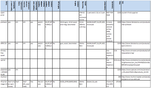
The selected autopilot will be either an APM or a Pixhawk
If the official APM is used then there is no real benefit to choosing it over the Pixhawk but if the arduflier or some other knock off version is considered instead than it may be worth it financially choosing it over the pixhawk
The final selected autopilot is the pixhawk due to the higher processing power which allows an extended kalman filter to be implemented which can lead to better state estimation. Another benefit of the pixhawk is the extra ports avalible for external sensors to be integrated with the software framework
-
Selection of multirotor platform
08/21/2014 at 02:03 • 1 commentI have a lengthy design document for the selection and design of the copter system being used in my development. Some select sections have been posted here for documentation purposes and the document will be included with my project.
(link to lengthier design document)
Project requirements
- The project shall be completed within the budget.
- The system should be able to resolve a 5cm by 5 cm logo.
- The system shall be able to resolve 20 by 20cm objects.
- The system shall fail in a safe manner that will not damage either the system itself nor pose any risk to the user, other people or objects in the vicinity of operation.
- The system shall be capable of imaging an area of 100m by 100m.
- The system should be able to image an area of 400m by 400m.
- The system should be capable of flying at a variable height with a minimum of 5m.
- The system should have minimum cost of upkeep.
- The system should require minimum training to operate.
- The system should be capable of operating outdoors.
- The system shall be capable of operating in light adverse conditions (light breeze).
- The system shall carry a 100g payload.
- The system should have enough battery to image the area in as few trips as possible.
- The system should have enough payload to support future sensor additions.
- The system shall carry a camera, onboard stabilisation, some means of connecting to a computer and be able to store the images.
- The budget shall include the mechanical parts of the craft, control electronics and batteries
- The budget should include radio receiver and camera.
- The system shall include the electronics required to allow autonomous recharging
Requirements due to legality
- The system shall have power monitoring.
- The system shall have a means of transmitting telemetry data in order to inform the operator of the systems operational status.
- The system shall have a means of failsafe.
- Radio transmission power and frequency shall comply with Australian regulations for all transmitters used.
- The system shall failsafe systems like return to base / flight termination.
- The system shall have a means to terminate the current operation and allow user control.
- The system shall be considered a small uav under casa regulations (under 100kg gross weight).
- The system shall not be commercial applications.
- The system shall not operate near structures, people or an aerodrome.
- The system shall not operate at a height higher than 400m.
Notes on copter design
The selection of components for the H550 and Q450 designs required many tradeoffs between price, payload, flight time and availability of components from as few distributors as possible in order to minimise money spent on shipping. Some justifications and reasons for the selections of components were
Propeller selection:
Larger Propellers
Higher thrust/payload capacity
lower flight time
Less responsive
Heavier weight
May burn out motors if they are too large
Limited by frame size
Smaller propellers
Lower thrust/payload capacity
Higher flight time
More responsive
Lighter weight
Useable on high kv motors
Battery selection:
Larger batteries
Higher cost
Higher flight time (with diminishing returns)
Less responsive
Heavier weight
Higher more battery cells
Higher thrust /payload capacity
Less flight time
Smaller batteries
Lower cost
Shorter flight time
More responsive
Lighter weight
Fewer battery cells
lower thrust /payload capacity
more flight time
Motor selection:
Higher KV
Higher thrust/payload capacity
lower flight time
More responsive
Limits propeller size
Higher power
Higher thrust /payload capacity
Less flight time
Able to turn larger propellers
Lower KV
lower thrust/payload capacity
Higher flight time
less responsive
can have larger propellers
Lower power
lower thrust /payload capacity
more flight time
limited in propeller size
There is a delicate balancing act between those three main copter components as seen above so there are a few rules of thumb that have been developed to try and guide designers
Try not to exceed a ratio of more than 0.5*weight to thrust to remain responsive for flight or more than 0.8*weight to thrust to be able to maintain stable flight. Lower weight to thrust ratios result in a more responsive system allowing acrobatics and advanced maneuvers. Hence aerial photography systems usually have a weight to thrust ratio of 0.5-0.8 since the system does not need to be responsive for flight and payloads are normally heavy due to gimbals cameras etc
For long flight times try to have a battery weight to copter weight ratio of 1gram copter and payload for every 2grams of battery you are carrying or even more battery. This is because the motors on copter systems require a large amount of energy to run and deplete batteries very quickly.
For long flight times pancake style motors with low KV, high power and large propellers ,but they are limited in the payload they are capable of carrying and these systems are more expensive as well
Other craft design considered
-Hexacopter, Octocopter and n-copter
Decreased flight time and increased cost compared to quad
Higher lifting capacity for additional future upgrades such as sensors or camera gimbals
Depending on the design there may be more stability in wind
This project does not require large payload capacities
Sometimes able to land safely after losing a motor or propeller mid flight
-Fixed wing
Can have much higher flight times ,but it comes with the trade off of maneuverability
Unable to hover to take still photos
No vtol
-Blimp
Can have large carrying capacity, but needs larger envelope. Can have huge flight time and hover
No off the shelf systems so everything must be custom
Considering the design limitations of the above systems I chose a build a hexacopter system to allow for the overhead of the experimental payload (which could be reduced in weight once sufficiently prototyped).