-
Software
10/16/2017 at 05:17 • 0 commentsThe Arduino software was pretty straightforward. I used a combination of tutorials and examples for all of the components from various sources to create the final sketch (available for download in the project zip). The Adafruit libraries for their Bluefruit ecosystem, as well as their LSM303DLHC breakout, made light work of the respective features in the sketch. The boost converter functionality didn't require any code, it just works because of how it's arranged on the PCB. Interfacing with the demultiplexer was also easy enough. Its four inputs A, B, C, and D are routed to A2, A1, A4, and A5 on the Feather respectively. The enable pin, which must be low for the mux to work, is connected to A3. From there, progressively turning on the inputs in a binary fashion results in connecting one of 16 motors to the 5V output from the boost converter. The sketch is a Frankenstein's monster of various example code and a few of my own algorithms, so I apologize if its readability is less than crystal clear.
Android is of course very compatible with Bluetooth 4.0, but I'm more comfortable with Xcode than Android Studio, so while I'm still alpha testing I only made an iPhone app. The app is a tab-based application with 3 sections. The first section has a Google Maps GMSMapView and a search bar. This is where the bulk of user interaction will take place. A destination can be typed in or dictated into the search bar. Then, an HTTP request to Google Maps should deliver a coordinate-based, precise route from the user's current location to their queried destination. The bearing to the next straight-line destination (for example, the closest intersection on the route to the final destination) is sent to the WGPS headband. The WGPS then combines this bearing with the orientation of the wearer's head that it has from the LSM sensor, and pulsates the motor that is the closest to this bearing. As soon as the wearer reaches within 15 meters of this via-point, the app switches to the next one. This process repeats until the final destination is reached.
Since the target audience for this device is the visually impaired, the app uses Siri's voice to give occasional status updates about the route, such as when big intersections are reached, and the estimated time remaining until arrival.
The second tab is just a table of available BLE devices that match the Feather's UUID, which is used to detect and connect to the WGPS. The final tab has a circular slider where any heading from 0° to 360° can be selected and beamed up to the device for debugging purposes.
The result is an intuitive and responsive interface for interpreting GPS directions that looks and feels very cool.
For those of you interested in making your own Swift app for use with the Adafruit Feather, here are some tutorials that I found very useful to get me going:
How to use the HM10: Connect your Arduino to an iPhone with Bluetooth
Create a Bluetooth LE App for iOS
Additionally, feel free to use any of my Swift code, downloadable from the Files section.
-
Controller
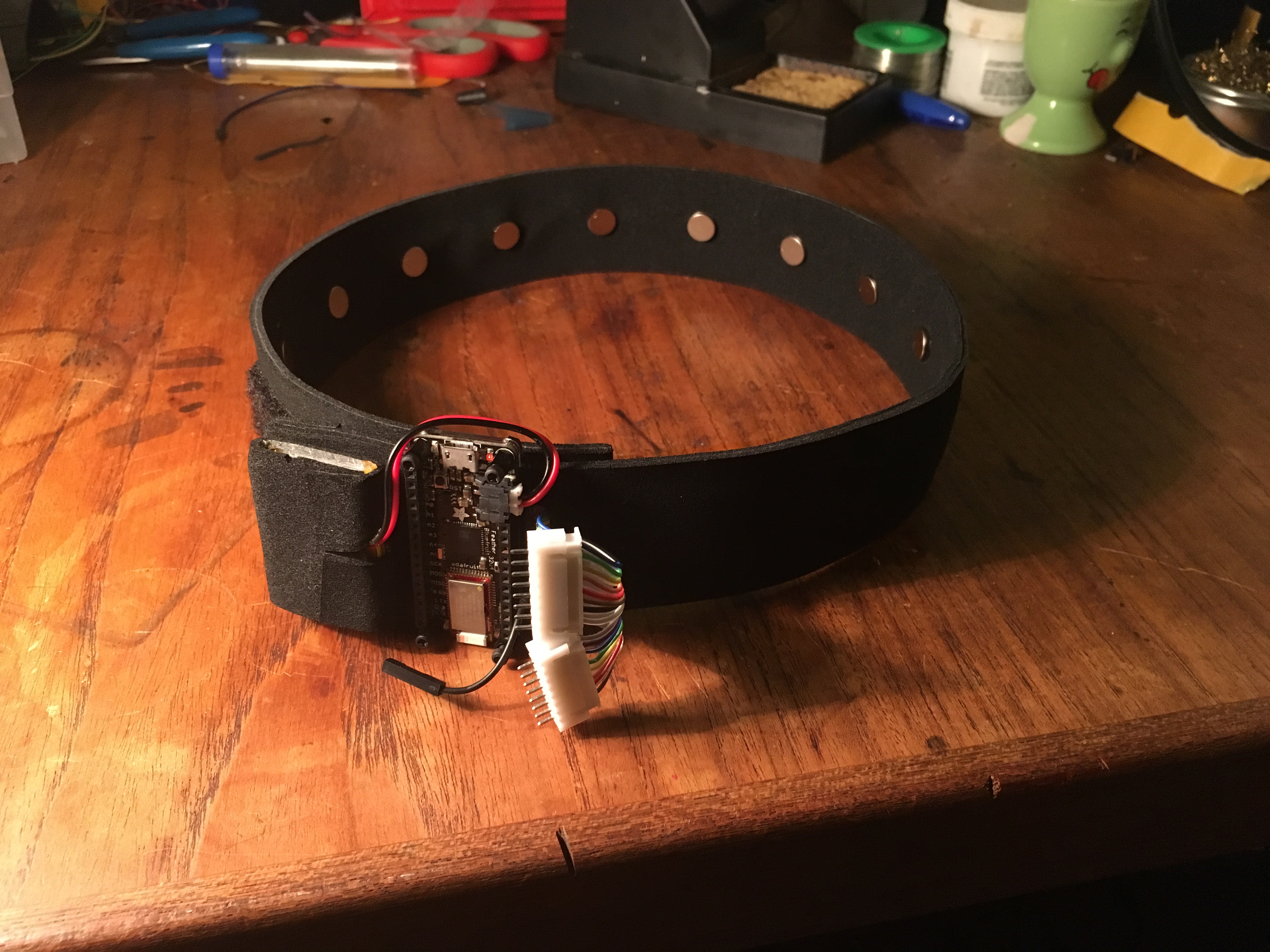
10/16/2017 at 04:38 • 0 commentsI used an Adafruit BLE Feather 32u4 as the microcontroller for this project. It takes care of Bluetooth 4.0 connectivity and hotswap-style LiPo charging all in a sleek 2" by 0.9" footprint, making it ideal for this application. I purchased special, shorter female headers (linked in the Components section) to mount my custom shield and keep the profile as low as possible. To sit snugly against the neoprene, I needed the bottom of the Feather to be completely flat, which would be impossible if I mounted the PTH header in the conventional manner. So, I trimmed the headers to be very short and used minimum solder for every pin, resulting in a flush bottom side. See the video for more details on this technique.
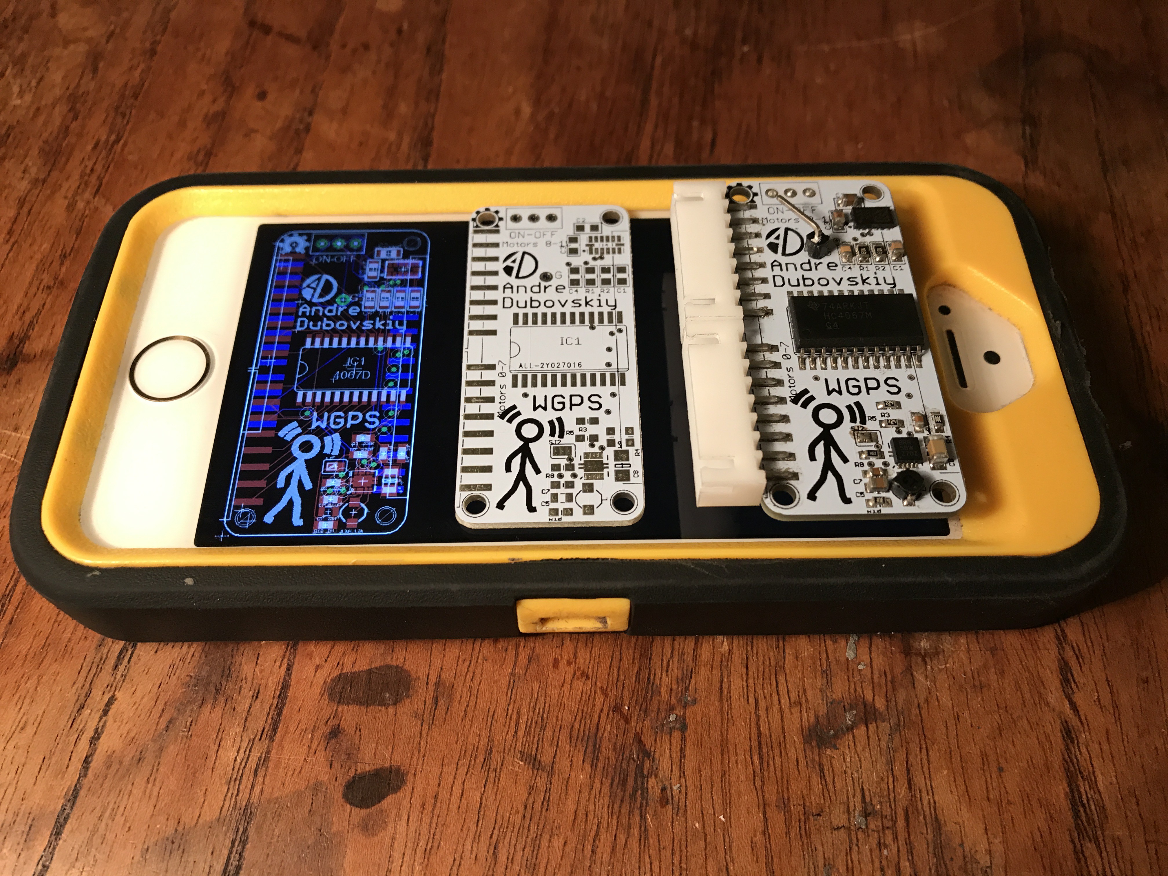
The shield was one of the hardest parts of the entire project. I designed my PCB in EagleCAD with two 8-pin JST plugs, LSM303DLHC tilt-compensated magnetometer, boost converter, and a 16-channel HC4067 demultiplexer from TI. For the LSM chip and boost converter I found open source PCBs from Adafruit and Sparkfun respectively, and integrated them into my design. I also ordered the corresponding PCBs, as well as a broken-out 4067 so I could play with all the parts on a breadboard to make sure they could be used the way I wanted. I added these PCBs to the Components section but keep in mind that all the components can also be purchased separately.
Many of the components were tiny and had QFN-like packages. Also, unlike Adafruit's "FeatherWings," I had to surface mount the headers to the bottom rather than with PTH, because otherwise I could not have broken out the female JST sockets to the side of the shield the way I did. My methodology here was inspired by this guy. I ordered the PCBs from allpcb.com. As far as Chinese fab houses go, these guys are very reliable. I paid a grand total of about $25 for ten 51x23mm boards, that arrived six days after I placed the order.
As soon as the boards came in the mail I began to eagerly assemble them. I used a solder paste syringe and tweezers to do all of the populating by hand. I don't think a stencil would have made the task significantly easier. When the board was ready, I used my hot air SMD rework tool to reflow the solder paste. On my first attempt, the boost converter didn't work. I think I may have put too much paste under the tiny TPS chip. Always use an absolutely minimum amount of paste for the teensy no-lead packages. Fortunately, upon my second try, everything was functioning. I could get sensor readings from the LSM chip with I2C and my motors were buzzing thanks to the 4067 demux and boost converter.
-
Wiring and Sealing Motors
10/16/2017 at 01:17 • 0 commentsWiring and sealing the headband was both tedious and very rewarding. The only actuators are the sixteen vibrating motors spaced throughout the headband, but to wire them carefully and compactly to the controller was no easy task. The skinny, fragile little wires of the ribbon cable had to be soldered to the even more frail motor power wires. Every connection was treated with heat shrink insulation. At the end of the ribbon cable, JST crimps and sockets were attached to the the wires. The ground wires of every motor were daisy chained all the way to the edge where one common ground header would come out.
In addition to all the motors and wires, I sealed a thin acrylic panel in between the two layers. This panel matched the footprint of the Feather exactly, and the microcontroller could be screwed on to the headband with no problem.
-
Designing & Laser Cutting Neoprene
10/16/2017 at 00:25 • 0 commentsNeoprene was the perfect material for this project. It's flexible, has a pleasant texture, and can be laser-cut. I own a $370 40W laser cutter from China. So far, this machine has been very reliable and awesome, with a sizable cutting area of 12" by 8". However, I wanted to make my headband out of a single strip of adhesive neoprene (linked under components). I found that the 99th percentile for head circumference is about 25", so I had to laser cut a 50" strip that would be folded in half. The strip is only 1.5" wide but the 50" length is much longer than the 12" I had to work with.
I used Illustrator to plan out the entire strip.
![]()
Then, I split up this file into two 11" sections for the motor windows, and a smaller section with the wire slot. The motor holes had to be aligned very precisely to one another, so I added a tiny mark in the top-right corner of the first section so I could put the laser. All of my laser cutting files, including the original Illustrator source, are available for download as a zip under Files, and on the project GitHub at https://github.com/andrehchs/wgps.
After cutting a 55" inch strip (for some leeway), I taped it to the bed of my laser cutter with some masking tape and started the cutting process. Once I cut out the first set of motor holes, I removed the masking tape, adjusted the neoprene strip such that the laser was aligned with the far edge of the first cut, loaded up the next cutting file and cut the next set of holes.
I used the LaserDRW 3 software that was included with my laser cutter, by importing the files as PNGs and selecting "Cutting" under the dropdown menu in the top right of the Engraving dialog. I used 1200 PPI bitmaps. I'm sure there are ways to cut vector files with a K40, but this method (of using absurdly high resolution bitmaps) worked fine for me.
I wasted some neoprene on stupid errors, but after two or three tries I was very happy with my results and the motors fit snuggly in their sockets.
 Andre
Andre

