Bud Bennett
-
Adding Smartport Telemetry to the Diatone Mamba Mini
02/17/2019 at 05:46 • 0 commentsI recently obtained an Armattan Gecko 4 inch quad frame. I wanted to build it with an AUW less than 250g, which is a challenge. I decided to use a Diatone Mamba mini stack to keep both cost and weight down. The rest of the build is Brother Hobby Avenger 1507/2800kV motors, A FrSky XSR-E receiver, a Caddx freestyle camera, and an AKK FX3 VTX. With a Tattu 4S 650mAh LiPo the AUW is just under 250g, but I'll probably fly it with a 4S 850mAh LiPo.
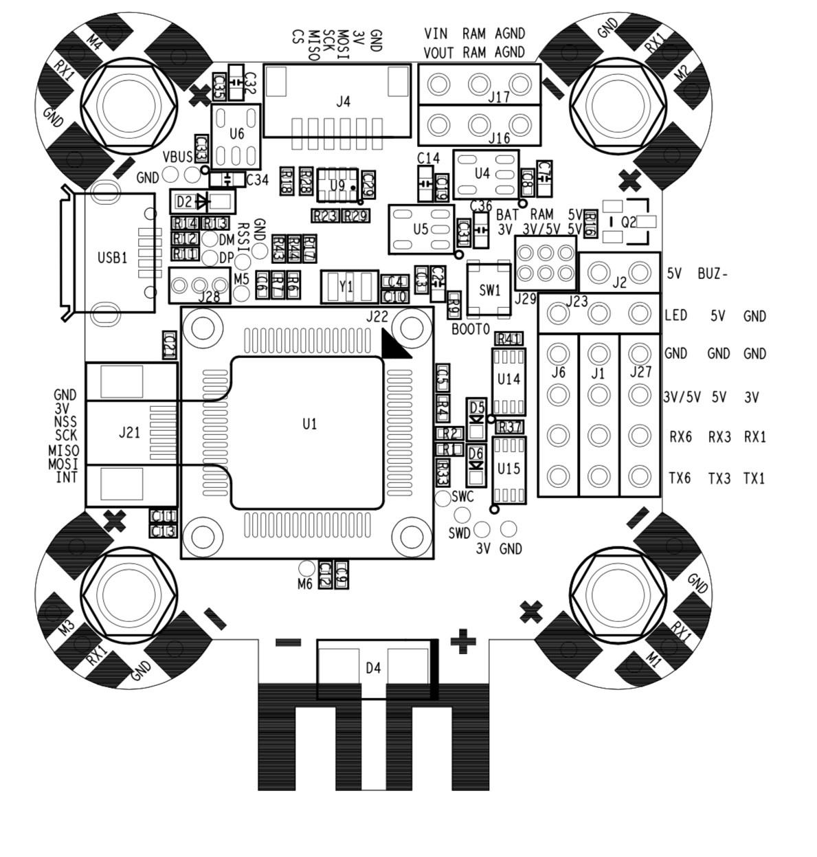
The Mamba mini is an F4 FC equipped with only 3 UARTs. I wanted to use SBUS for the receiver, smart audio for control of the VTX, and Smartport for the telemetry back to the Taranis transmitter. The Mamba only has an inverter on UART1 to service SBUS. I tried to get Smartport working on TX1 and TX6 with soft serial, but it doesn't appear to be implemented on the Mamba. The only option was to use the Smartport inverter -- I set it up on UART6, using VDD = 5V with no issues.
The telemetry settings:
tlm_inverted = OFF
set tlm_halfduplex = OFFThere is still a need for this inverter when using some F4 flight controllers like the Mamba. I have not yet migrated to F7 flight controllers -- they are a lot more money and the F4 FCs still work pretty well.
-
PCB Variations
07/30/2018 at 14:10 • 0 commentsI got a suggestion for two variations of the SmartPort Inverter -- one with all the components on a single side of the PCB (for easier soldering), and another single-sided variation that uses the DMN601DMK part, which includes both MOSFETs in a single SOT23-6 package. I spent some time on each of these designs with varying results.
Two-sided to Single-sided Conversion:
There is no way to prove that any particular layout is the absolute smallest possible (IMHO). I spent as much time as I was willing to create the single sided PCB below.
![]()
The components could probably be packed a bit tighter, but it might make soldering more difficult. As it is, the PCB is quite a bit larger than my original 2-sided PCB at 0.37 x 0.38 inches (9.4 x 9.7mm) -- 3 boards will cost $0.70. If you wish to make this board be aware that I have not made one myself, but it is checked for design rule errors and connectivity. One benefit to a single sided PCB is that the pad labels are placed on the back side, which makes it easier to connect the wiring harness.
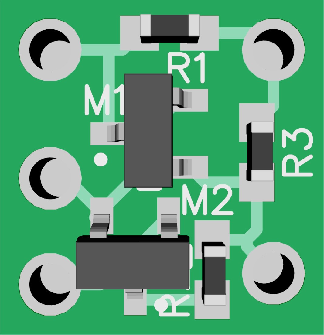
Another version for the DMN601DMK:
The DMN601DMK is a part that includes 2 MOSFETs in a single SOT26 (SOT23-6) package (There are other dual MOSFET parts that might be suitable as well). The thought (not mine TBH) was to make a single sided PCB as small as the double sided PCB. I had two objections to this approach: multiple components in a single package are sometimes more difficult to hook up efficiently and may not lead to the smallest layout area, and there is a possibility that the package could be rotated 180° when soldered. Both of these concerns were unfounded.
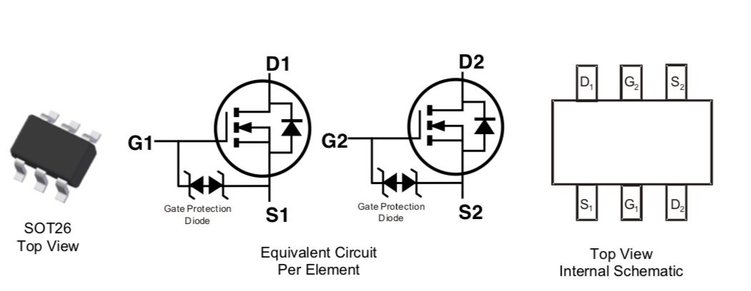
The package and schematic for the DMN601DMK is shown below. Note that the package can be rotated in either direction while maintaining the same connectivity. The pins are not even numbered in the data sheet. I did, however, have to create a new component in order to use this device in the schematic and layout. You can get this part from Arrow.com or Digikey in small quantities. (Note: The SOT363 is NOT the same package as the SOT23-6. The SOT363 is a 6-pin SC70 package with a pin pitch of only 0.65 mm vs. 0.95mm for the SOT23-6. It would be very difficult to hand solder the SOT363, but possible to hand solder the SOT23-6.)
![]()
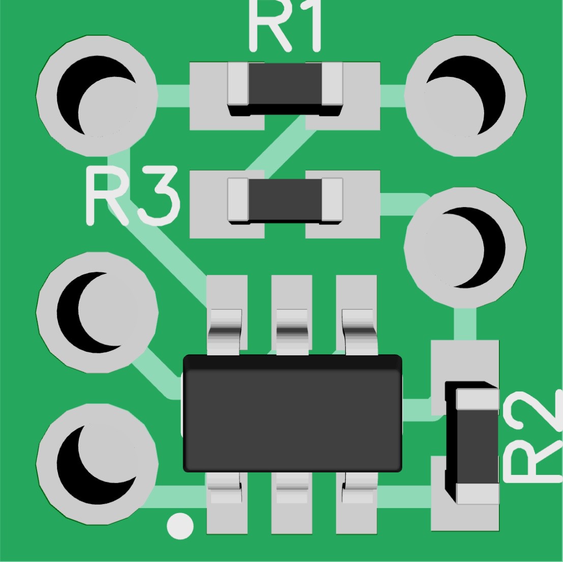
Here's my final attempt at the PCB:
![]()
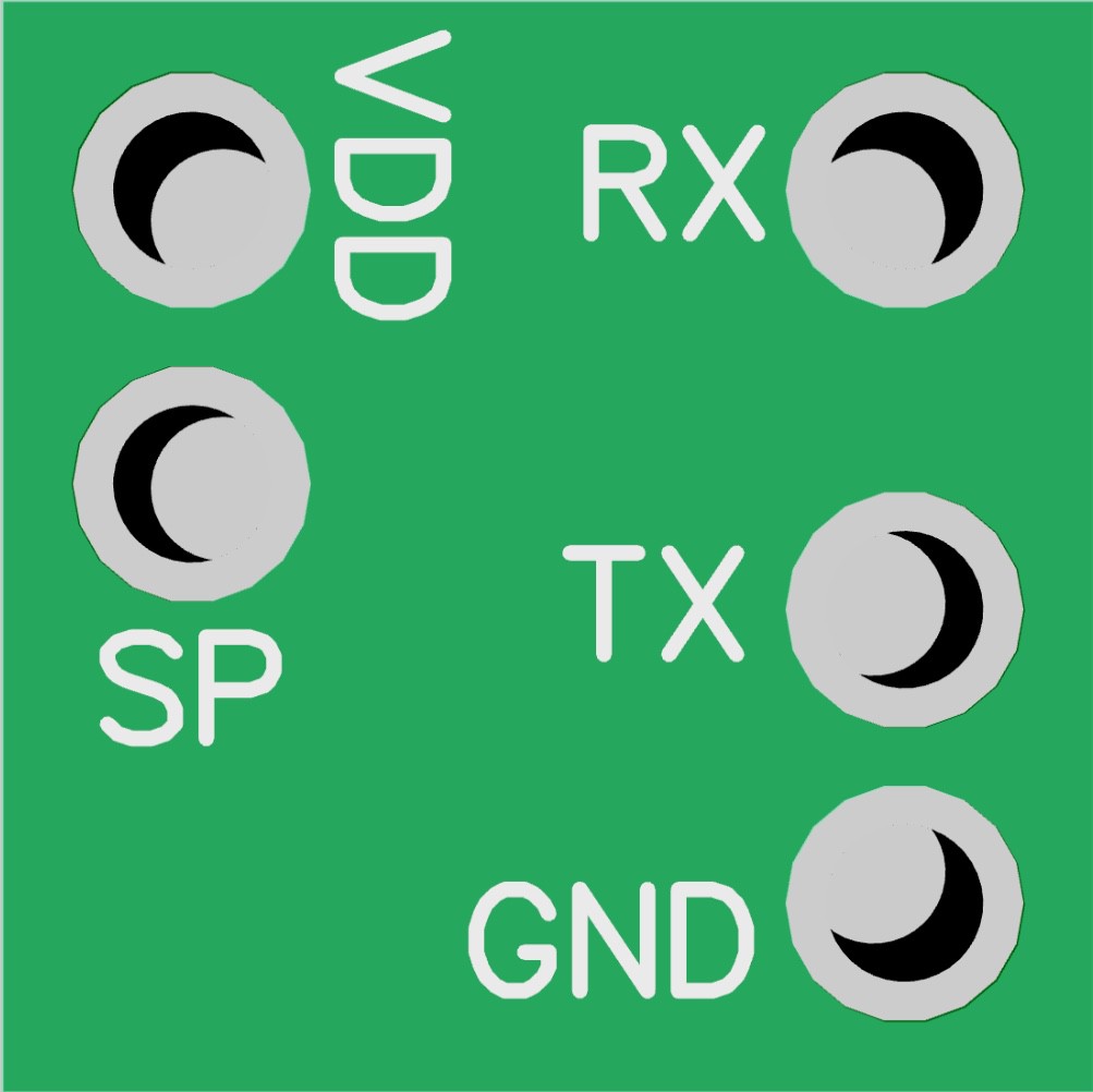
The back side is nicely labeled:
![]()
The PCB area is 0.33 x 0.33 inches (8.4 x 8.4mm), which is only slightly larger in one dimension than my original double sided PCB. 3 boards from OSH Park will cost $0.50 -- same as the double sided PCB.
I uploaded the gerber files to this project's "Files" area if you want to make PCBs for yourself. Disclaimer: The design rules and connectivity are without errors, but I have not fabricated these boards. Caveat Emptor.
-
Accommodating VDD = 3.3V
07/23/2018 at 00:50 • 5 commentsI had a problem with an Chinese clone of an Omnibus F4 Pro Corner flight controller. I connected the smart port inverter to VDD=5V and found that the gyro noise was so high that I had to set moron_threshold = 0 to get the quad to arm. Any value larger that zero for moron_threshold would not allow the quad to arm consistently. It was not obvious what the problem was until I cut the smart port inverter out of the system and the gyro noise disappeared. Q.E.D.
I was suspicious, however, and measured the voltage on the the UART6 TX/RX pins at 3.3V, even though the inverter was connected to 5V. I decided to reconfigure the smart port inverter to operated at VDD=3.3V. The solution was to replace the 2N7002 MOSFET with a MOSFET having a lower threshold voltage that allowed operation at 3.3V. I did not trust the 2N7002 to switch properly when using a 3.3V supply because it has a large specified maximum threshold voltage of 3V, which is pretty close to VDD.
I decided to substitute a 2SK3018 MOSFET for the 2N7002. The 2SK3018 has a max VTH of 1.5V, which is better suited to the lower VDD value. Unfortunately, the 2SK3018 is an obsolete part, but still available from eBay sources. Alternatively, the DMN65D8L MOSFET has a threshold between 1.2V and 2.0V and is probably still active. There are probably other MOSFETs that will work at the lower VDD if the max. threshold is below 2.0V
I changed the VDD supply for the smartport inverter to 3.3V by configuring the Corner flight controller to provide 3.3V on the 3V/5V pin via the jumper adjacent to the j2 pads:
![]()
After I made the changes to VDD the telemetry worked again and the gyro noise disappeared, so now moron_threshold = 32, the default value, and the quad arms without any issues.
Conclusion:
I suggest that going forward that a lower threshold MOSFET like the 2SK3018 should be substituted for the 2N7002. This should allow operation at VDD=3.3V and VDD=5V. Be careful to match the VDD of the smart port inverter to the VDD used by the UART that it is connected to.
-
Success!
10/31/2017 at 21:37 • 0 commentsThe inverter circuit appears to work as advertised. I was able to get the correct telemetry displayed on my Taranis transmitter. Here's the procedure:
I hooked up the inverter board to +5V, GND, TX3 and RX3 on the DYS F4 flight controller board. I also connected the inverter input to the smart port lead on the XSR-E receiver (the thin blue line). Here's the inverter next to the receiver.
![]()
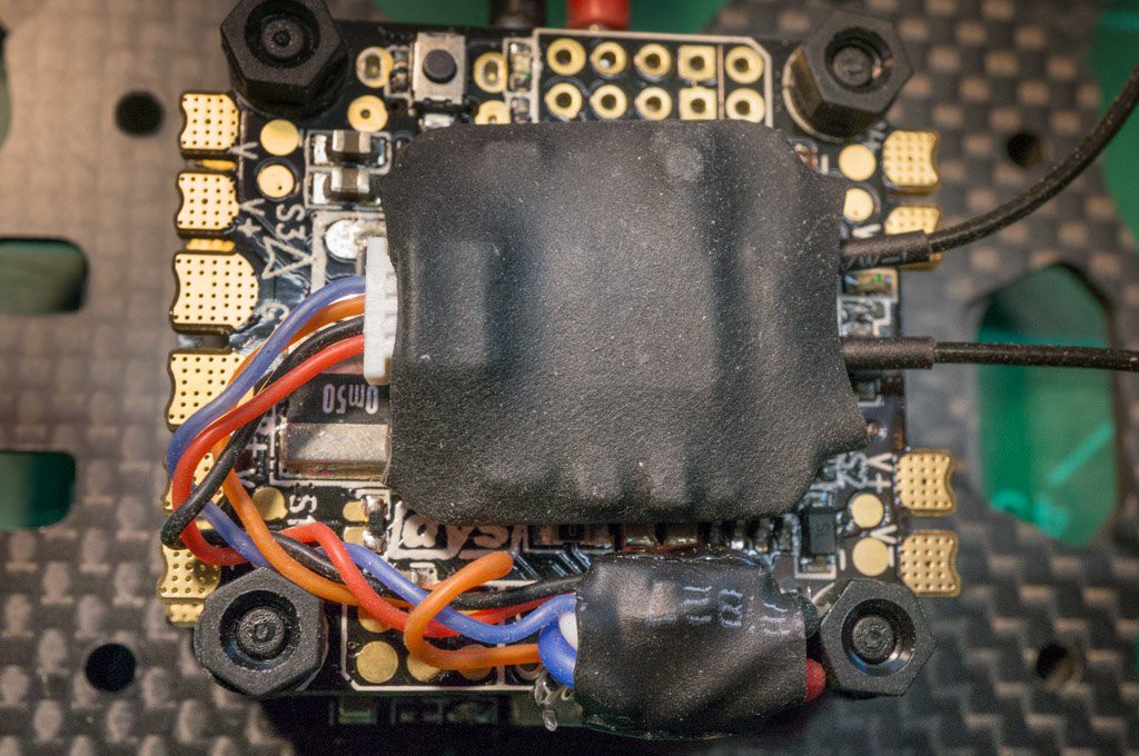
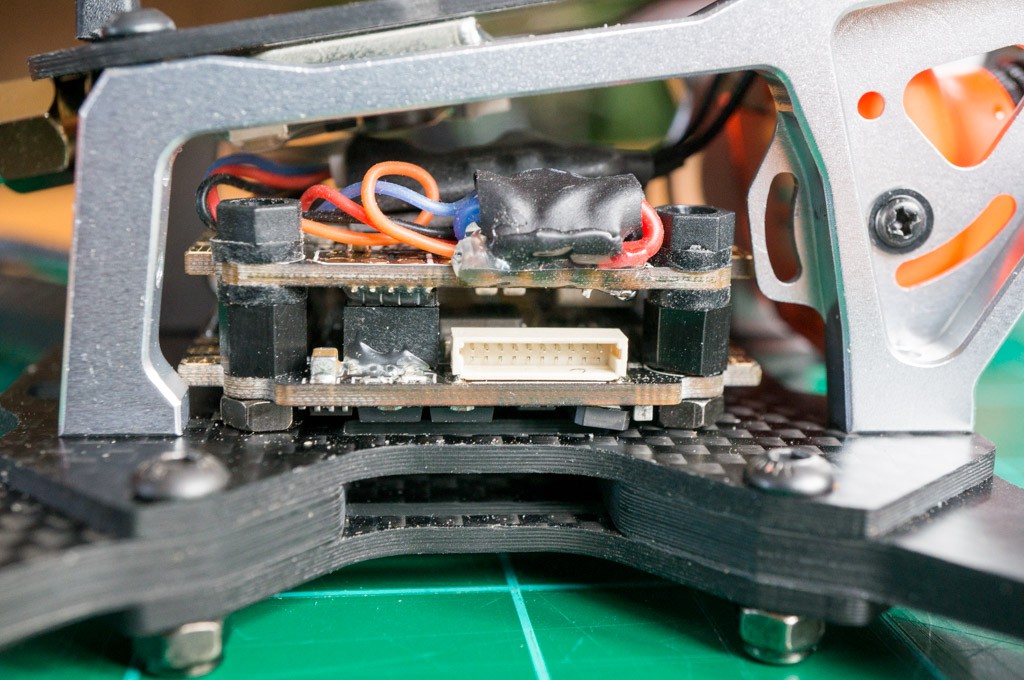
I then hot-glued the inverter to the flight controller board to reduce stress on the wiring. I attached the receiver with double-sided sticky foam tape. Both items are pretty small compared to the flight controller. Here's a side view of the stack:
![]()
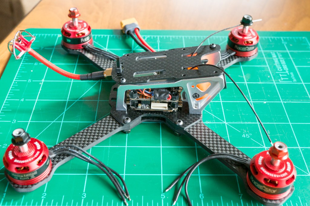
This quad uses a Transtek Frog Lite frame so there is very little room within the housing. Fortunately, everything fits fine. Here's a top view of the entire quad in a mock-up state (I'm waiting for some 20AWG silicone wire so I can hook up the ESC to the motors.) There's not much room.
![]()
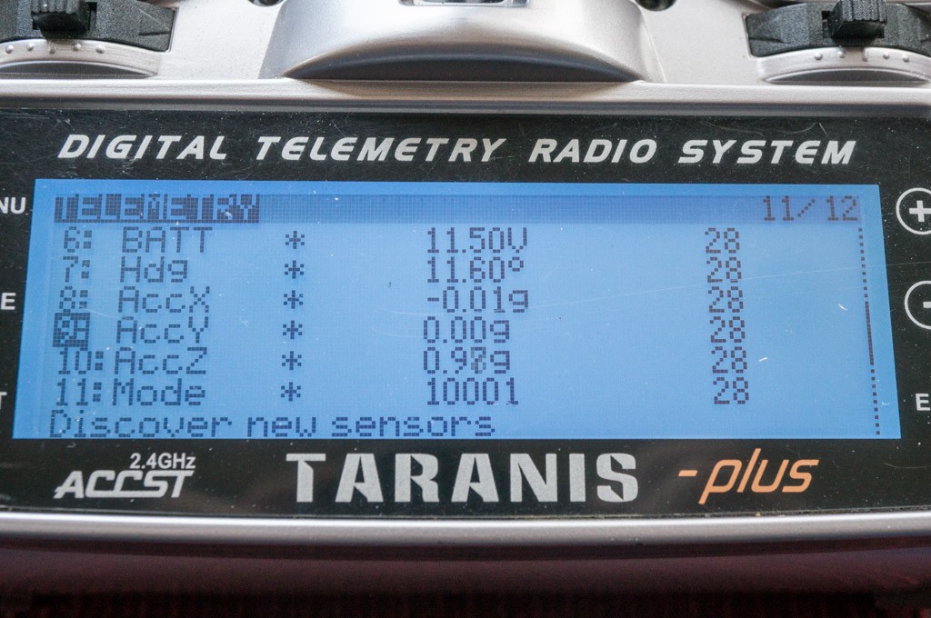
The next step was to configure the telemetry properly in the iNav configurator. I assigned the smart port telemetry to UART3. It took me a while to realize that I had to "set smart port_uart_unidir = ON" in the command line interface. After that, the Taranis was able to get the telemetry from the quad:
![]()
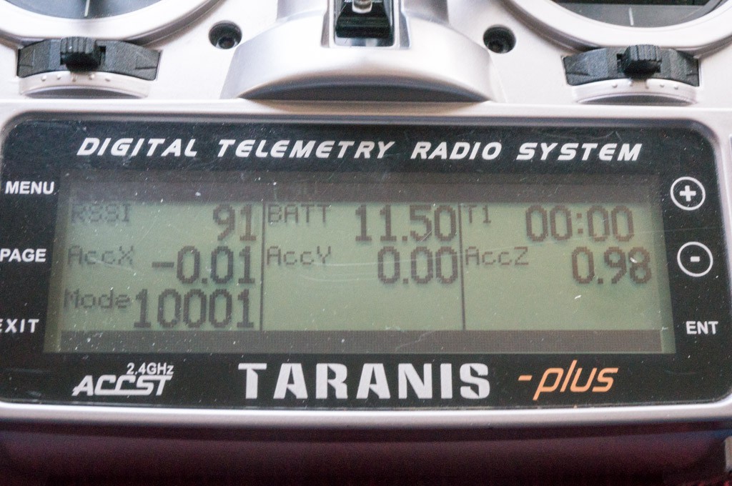
And I set up the sensor display temporarily:
![]()
At this point I'm pretty much done with this project. Things are working and I don't expect any problems with the smart port inverter going forward.
FrSky SmartPort Inverter
A compact hardware solution for interfacing the FrSky SmartPort to a F4 (or possibly other) flight controller.