 andrew
-
1hackaday.io fix build instruction sorting bug
I tried adding all of the build steps but due to a sorting bug they ended up in a random order. The bug is supposed to be corrected soon so hopefully I can try adding them again this weekend.
-
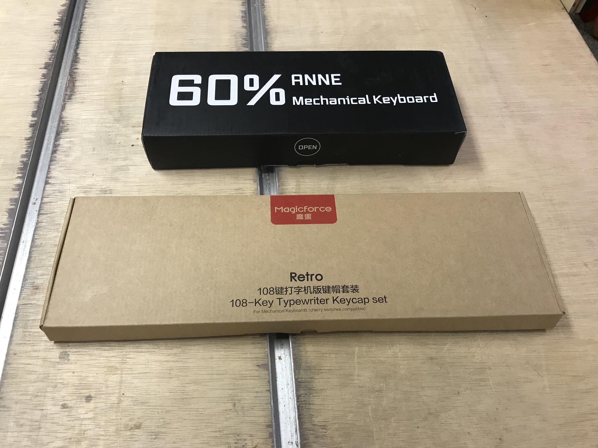
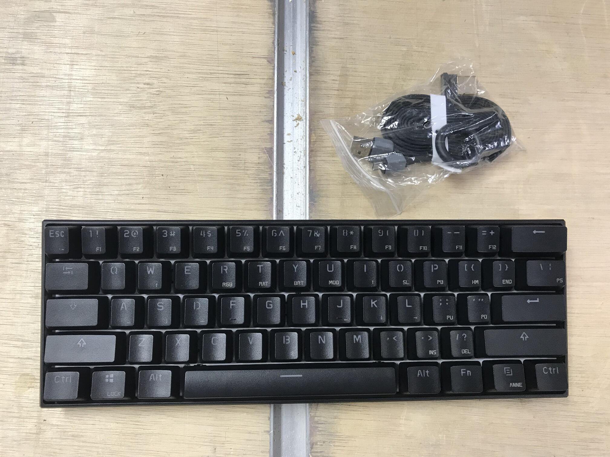
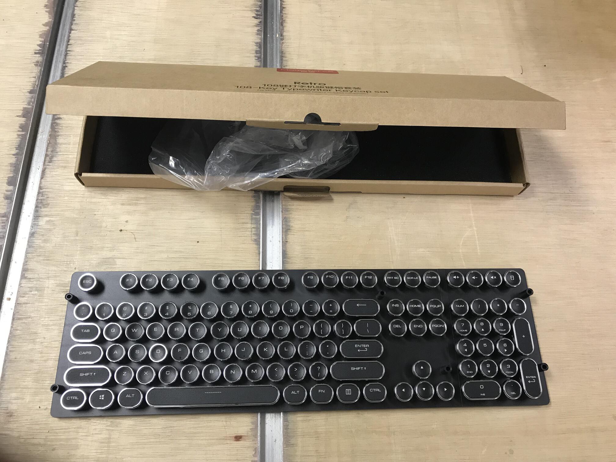
2Unboxing
![]()
![]()
![]()
-
3Make circuit board standoffs
![]()
![]()
![]()
![]()
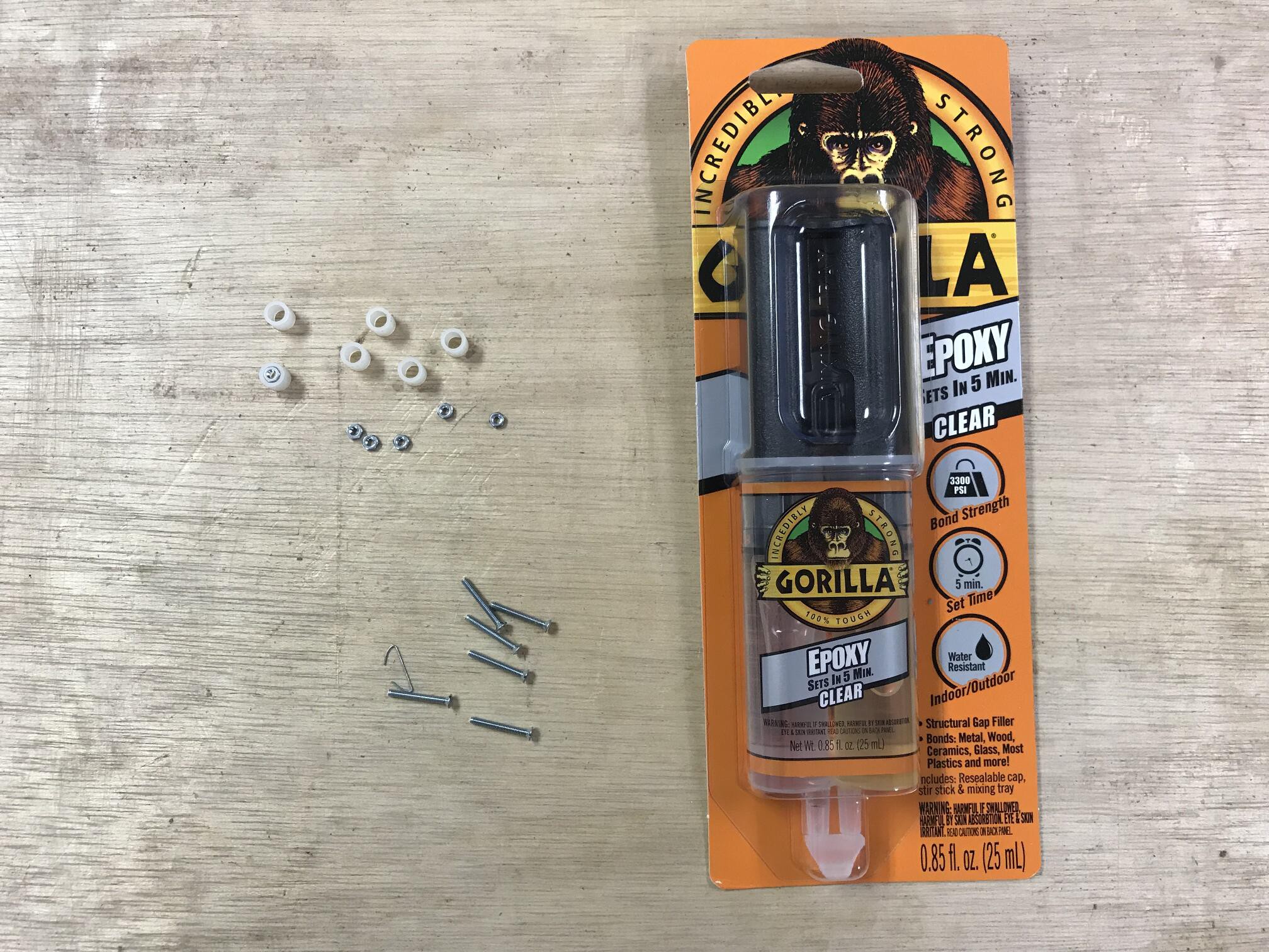
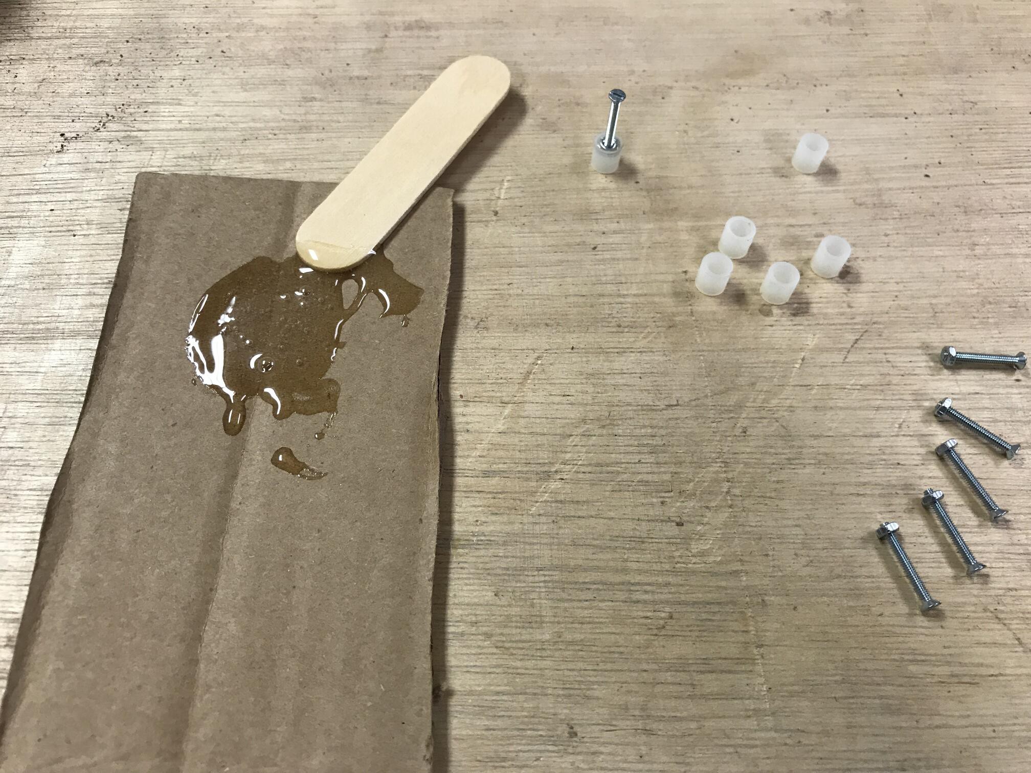
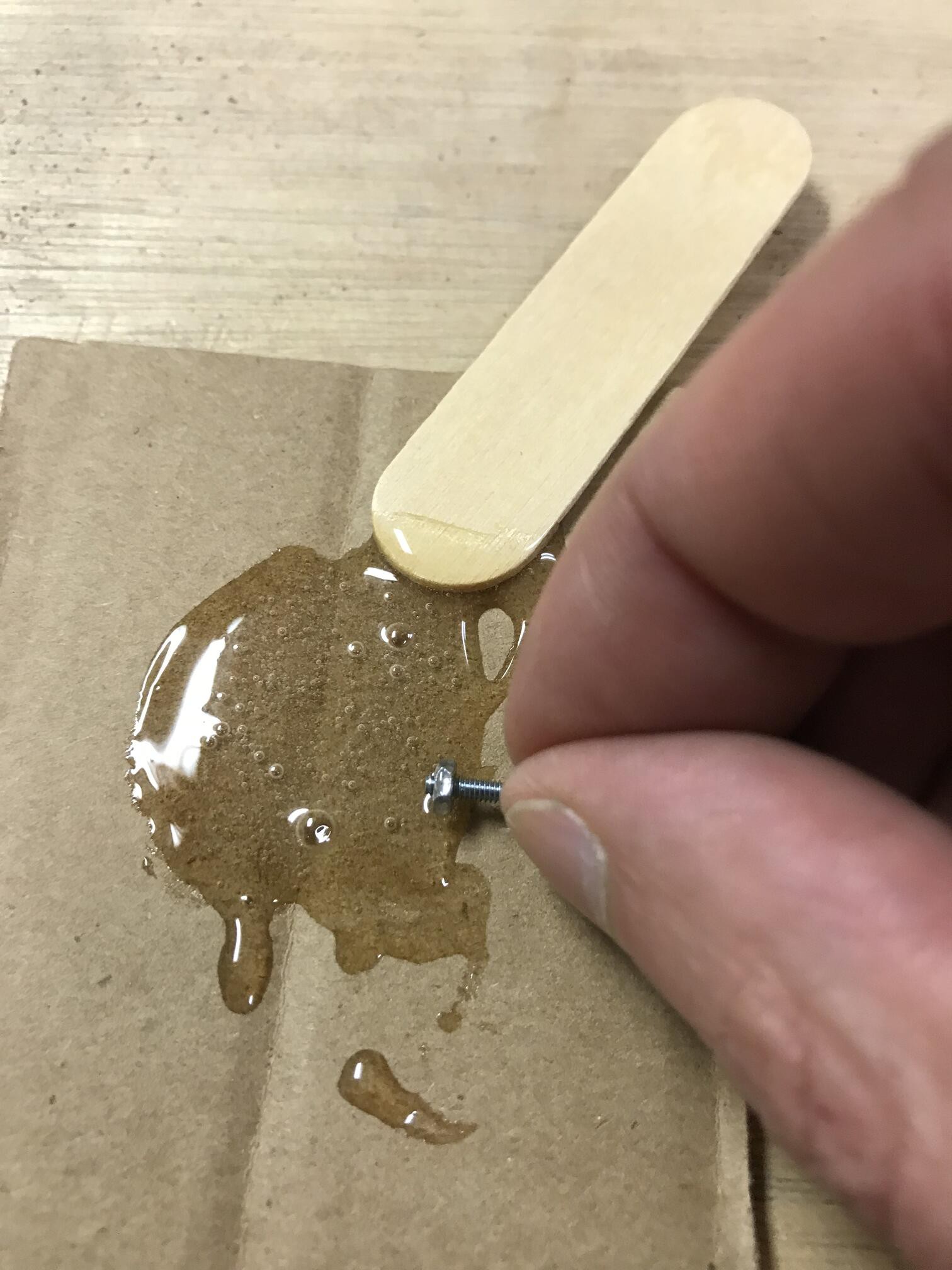
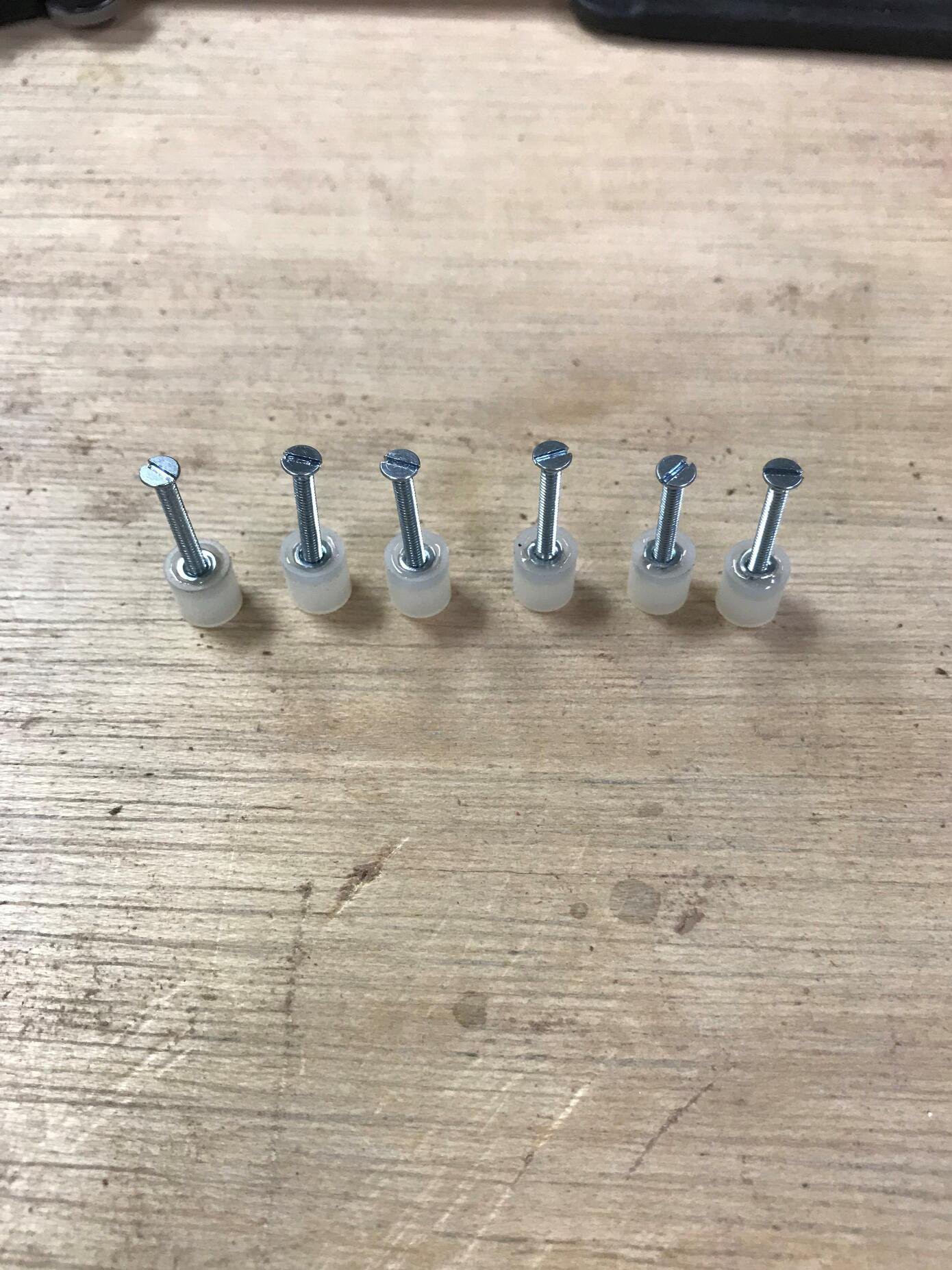
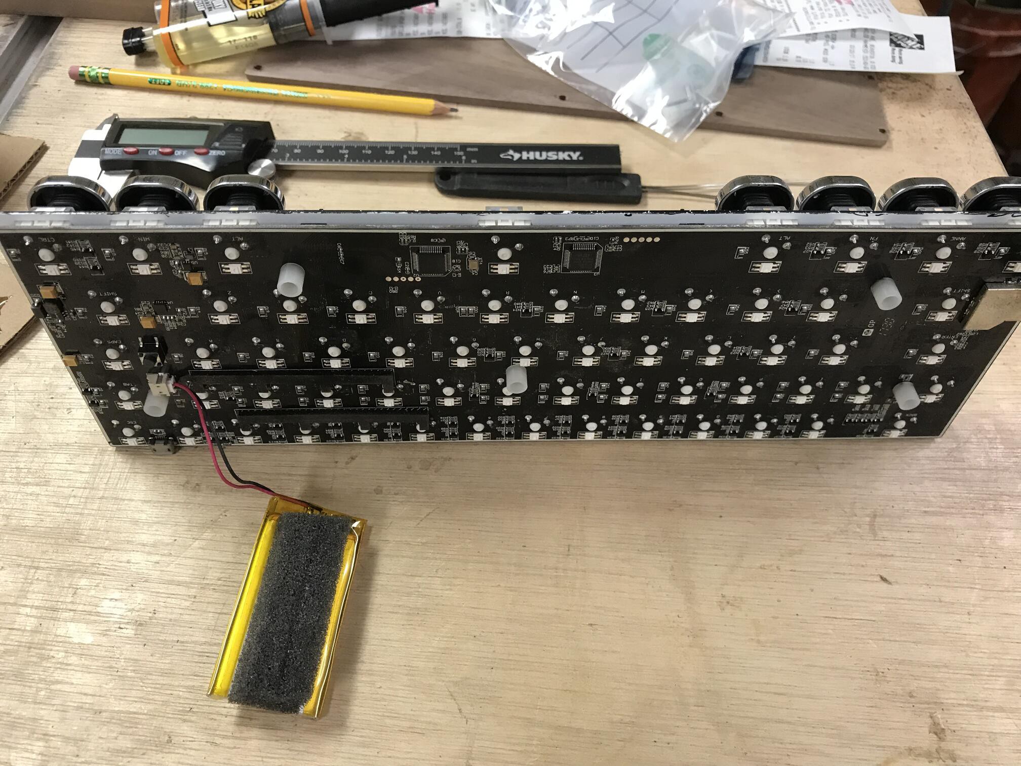
For the circuit board standoffs, I found nuts that were the same size as the anne keyboard screws (m1 I believe, but i cant recall now maybe m2?). Next I found some nylon spacers that were just large enough for the nuts to snugly fit into. Even though I only needed 5, I grabbed 6 of each planning for an oops with the epoxy. I also grabbed some screws of the same size but longer length just to use as handles during this process. I threaded the nut a few turns onto the screw, then rolled the outer edges of the nut through epoxy before pressing it into the insert. I aimed to get the nut in just a bit further than flush with the top edge of the space so that when attached the circuit board, there would be no risk of the nut itself touching anything. I left the long screws in while the standoffs dried to ensure that no epoxy was pulled into the threads of the nuts.
-
4Replace key caps
![]()
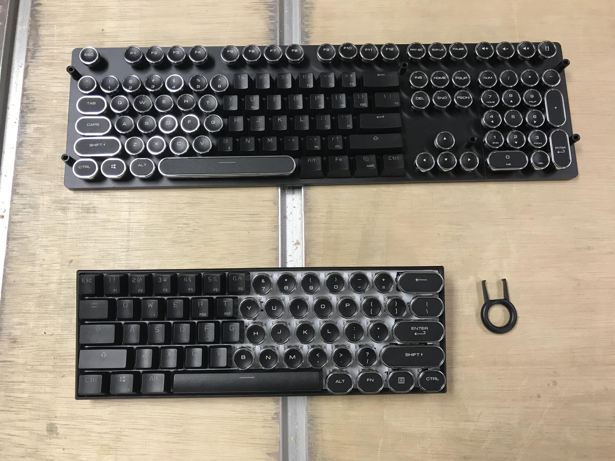
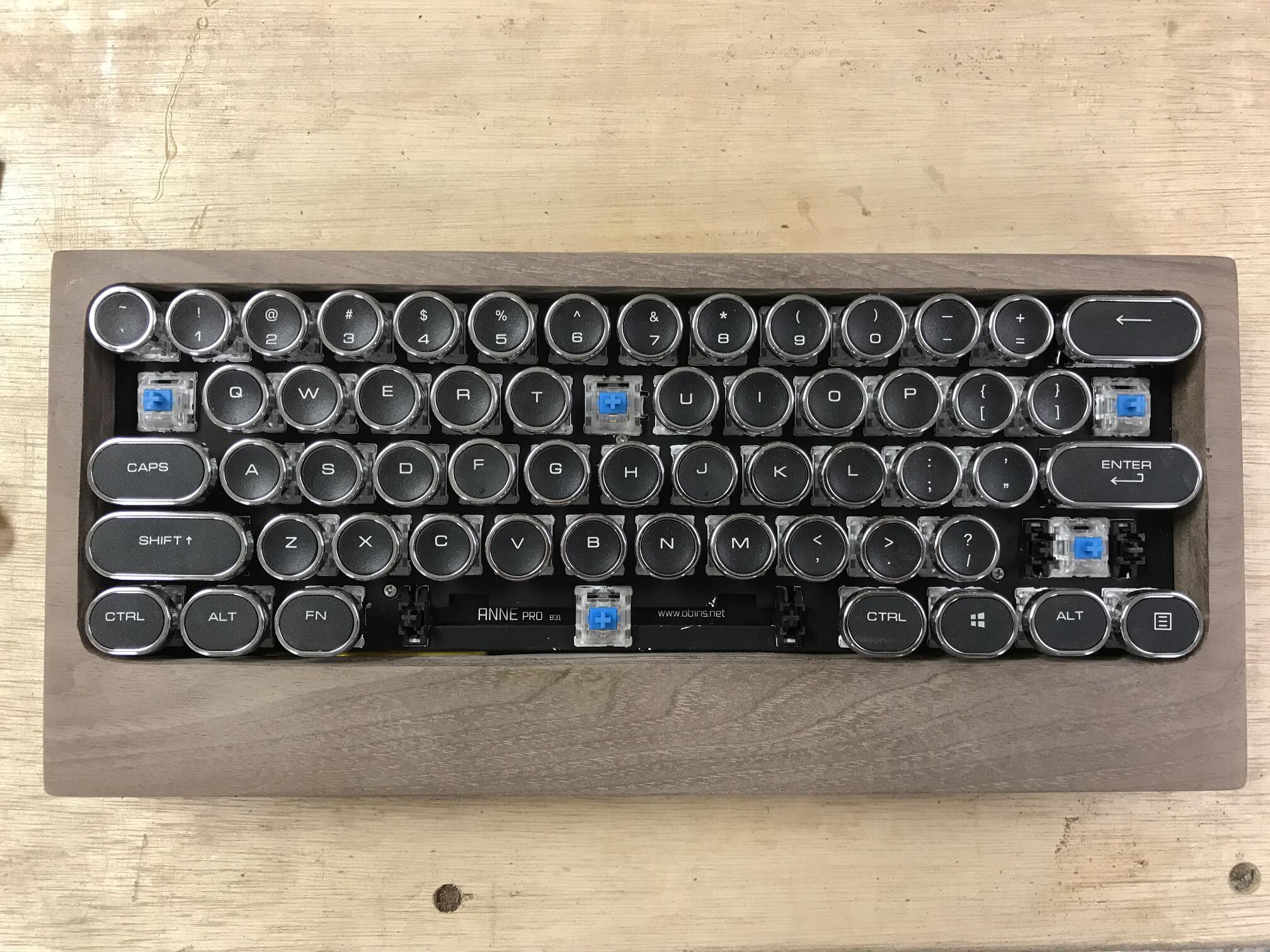
There was no reason to replace the key caps at this stage and it just meant that I would need to take them off again but I was impatient to see how they looked. Note key puller that came with the anne to the right of the keyboard. No complaints about a free puller but, the wire loop ones are much nicer and I did end up buying one because when I tried to use the one in the picture on the new keys, it began to pull the silver rims off of the keys
-
5Epoxy standoffs to the case bottom layer
![]()
![]()
![]()
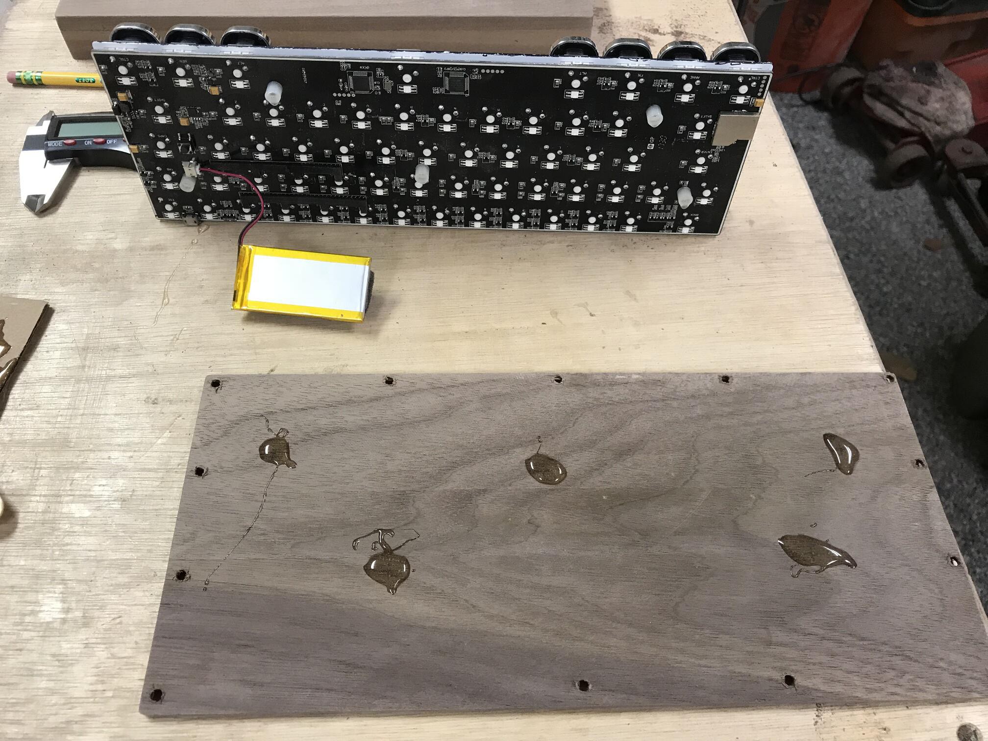
Once the standoffs were dry, I used the original anne screws to attach the standoffs to the back of the circuit board. I then laid the board down on the case back layer in roughly the right location. I marked the spots where the standoffs made contact. Next I dropped some large puddles of epoxy at those locations and then placed the board back in place so the standoffs were in the epoxy puddles. Finally, I played the top two layers of the case in place around the circuit board and aligned the outer edges of the case. I then aligned the circuit board to ensure that space between the case and the corner keys was even all the way around. I then left it for the standoffs to dry in the epoxy puddles.
-
6Remove the circuit board from the case
![]()
To remove the board, pull of the key caps as shown in the photo and remove the 5 screws that attach the board to the case. The board is free after that but its a very snug fit. I ended up holding the back of the case in one hand and slapping it face down in my other hand until the keyboard fell out into my free hand.
-
7Adjust case thickness and test fit
![]()
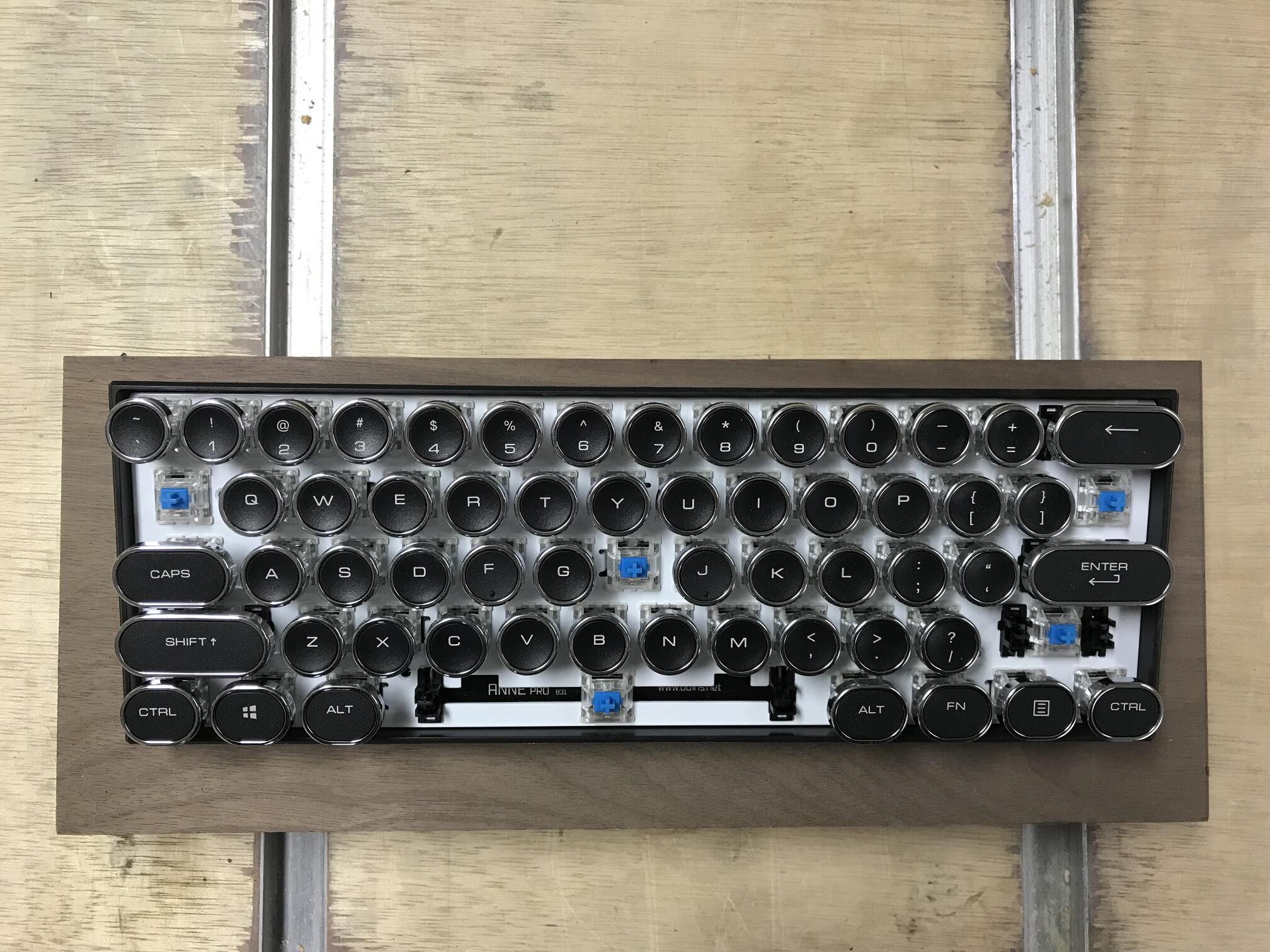
Once the standoffs were dry, I removed the back layer (with circuit board attached) and trimmed a bit of material off of the back of the top portion of the case to make final adjustments to the overall case thickness. Once I was happy, I added a slight bevel to the "wrist rest" area of the board and reassembled. Phase 1 complete!
-
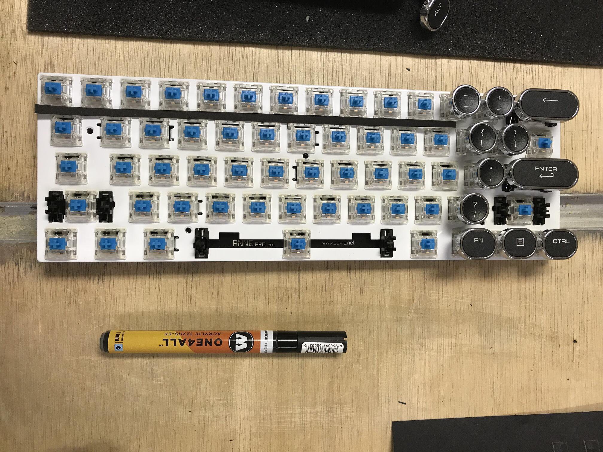
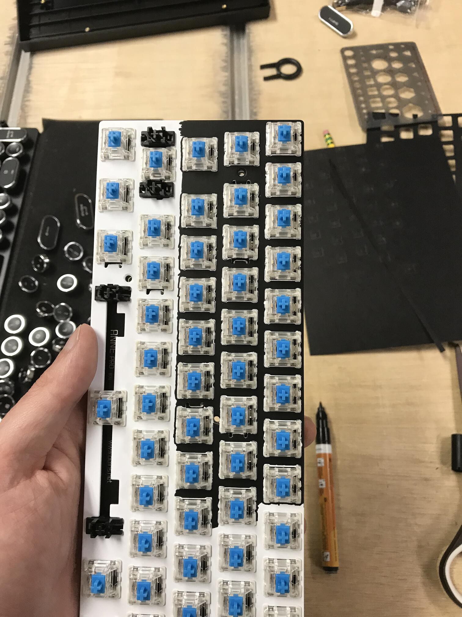
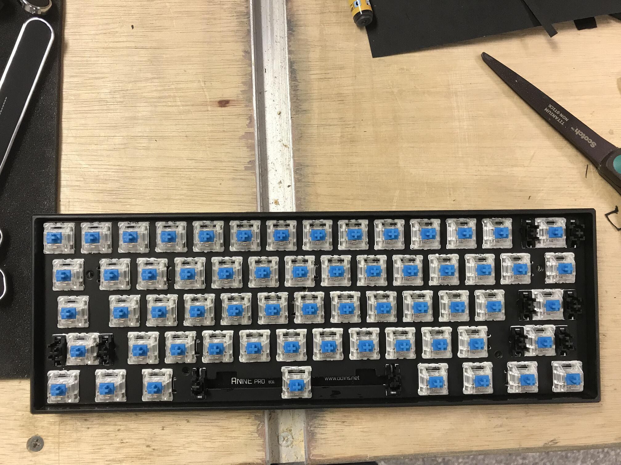
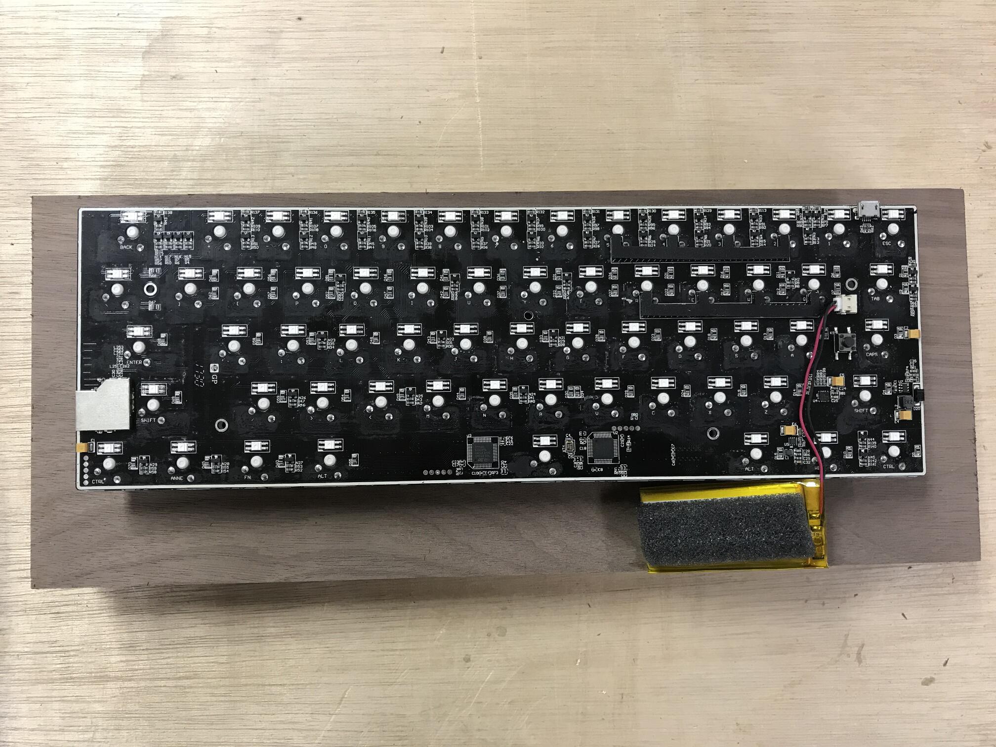
8Paint the circuit board black
![]()
![]()
![]()
I didn't like the look of the white circuit board behind the keys. It might look great on another build but I thought with the dark walnut case I had planned it wouldn't be a good fit. After looking at a few options, I ended up deciding the easiest way to solve the issue was just to use a black paint pen to paint the front of the board black.
-
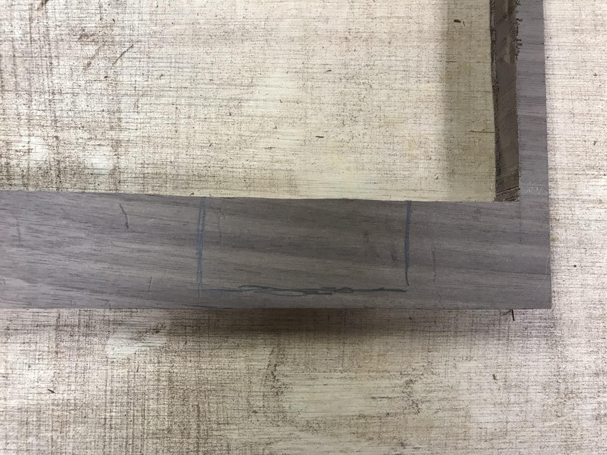
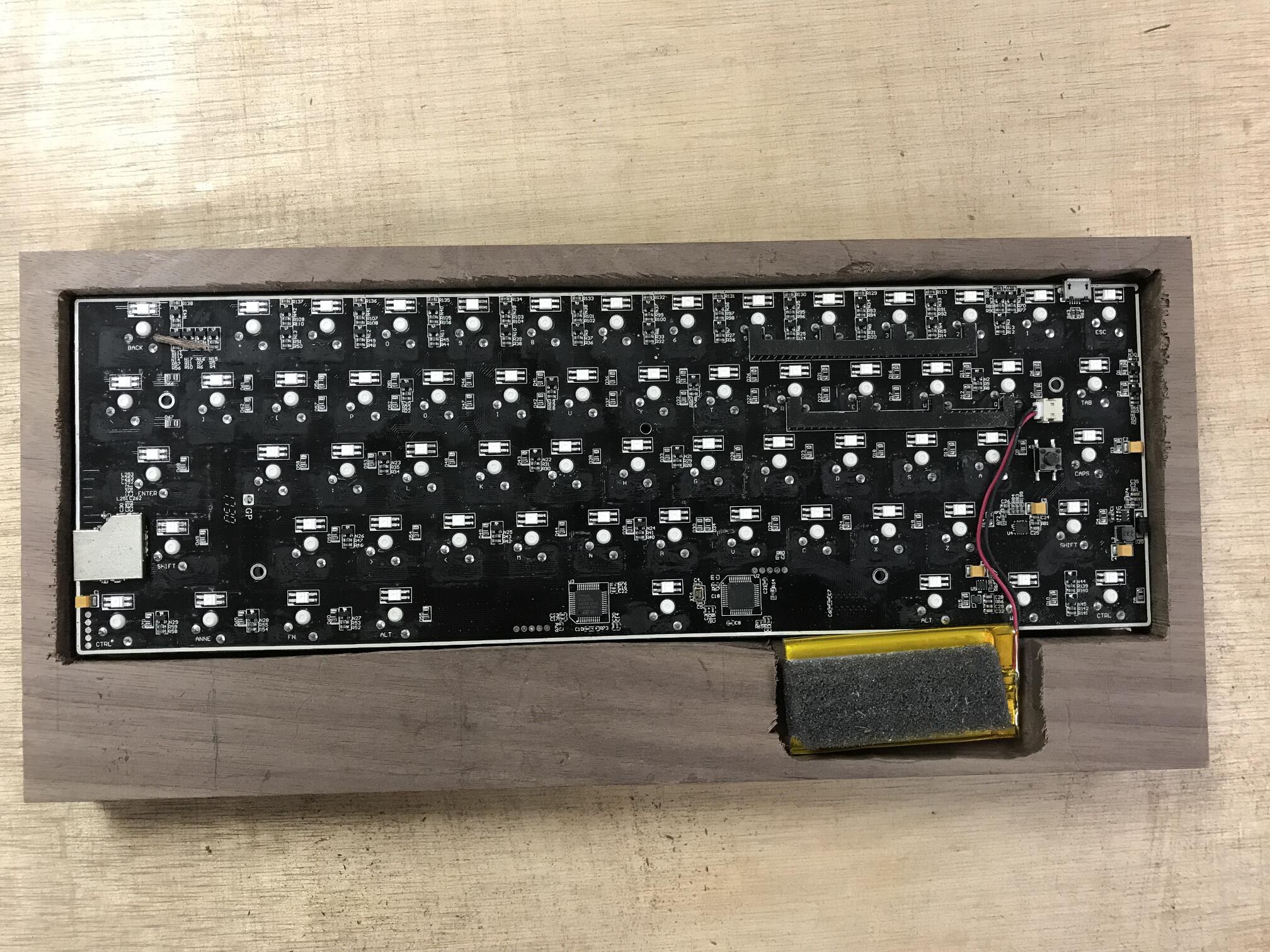
9Make the middle layer of the case
![]()
![]()
![]()
For the center layer of the case, I just rough cut an opening in the center large enough to house the circuit board and then routed out a small area for the battery to sit. This layer will form the bulk of the case but will be sandwiched between a top and bottom layer so I am not concerned with the cuts looking especially nice.
-
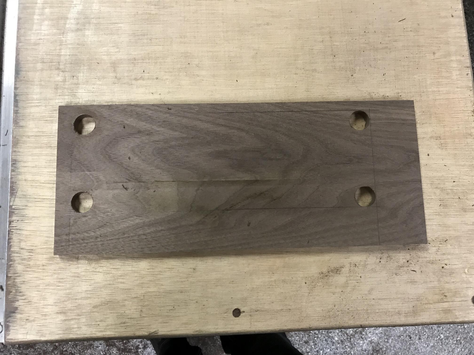
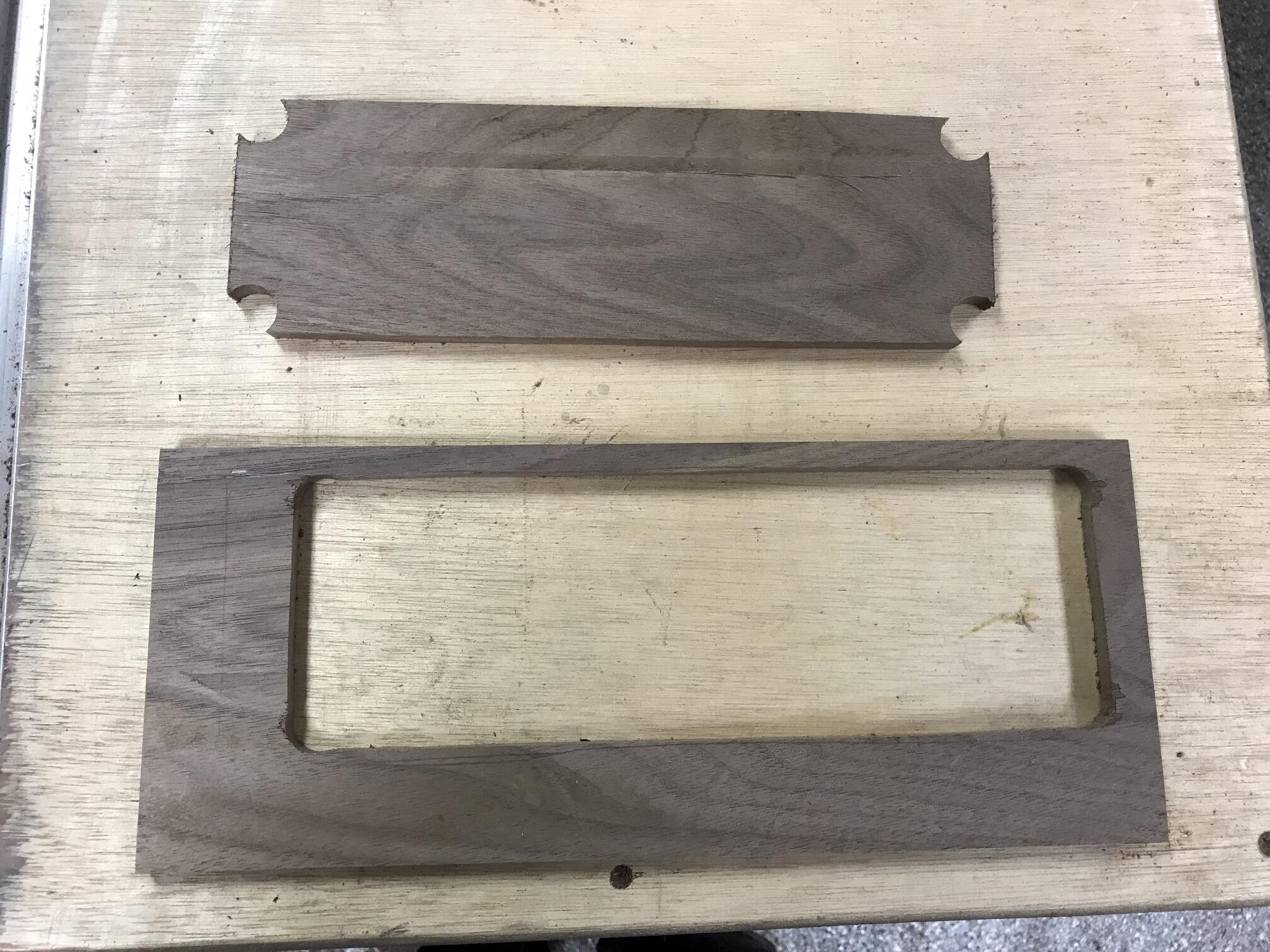
10Make the top layer
![]()
![]()
For the top layer, I cut the opening with rounded corners to match the profile of the keys. Note the outside edges of the top layer are still uneven at this point. Once all three layers are assembled, then I will trim all of the edges to be even. This layer is thinner then the center, roughly 3/8"
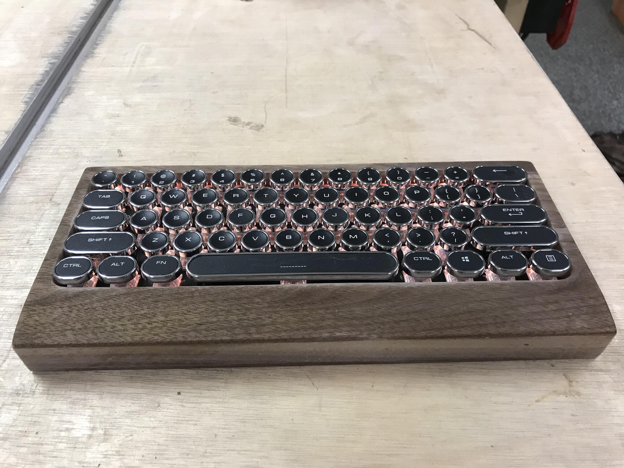
Customized wireless mechanical keyboard
I needed a custom keyboard to match an antique radio project I am working on. This was the result.
Discussions
Become a Hackaday.io Member
Create an account to leave a comment. Already have an account? Log In.