hackaday
-
Characterizing A New Sensor
03/12/2018 at 19:32 • 0 commentsI got a promising candidate as a substitue for the GUVA-S12D. I have a 405nm UV LED which tracks a GUVA and VELM sensor in daylight well. It has a further advantage of outputting a voltage almost in range of the 2.56V internal reference. I find a 1 M resistor in parallel with the LED is enough to pull down the voltage within the upper bound of 2.56V.
This will enable me to get the parts count down siginificantly. I can drop the op-amp and the associated passives. My LED is $0.18 in quantity.
I noticed it is more sensitive to my 385nm LED flashlight than the GUVA, so I'm using real sunlight to gather readings. I'll need to wait for the sun to get higher in the sky (or a sunny day in the mountains) to get up into the 9-11 UVI range. 11 will be enough to get to the "extreme" range. I plan on simplifying the readout into the four cateories of "low", "moderate", "high", and "extreme". -
Rev 0.1 Boards In - Qualified Success
12/27/2017 at 00:33 • 0 commentsI got the boards back from Seeed about a month ago and was waiting on the delivery of the GUVA-512D sensors from China. Wish I could afford to buy them direct from Roitner Technik, but not at >$5 each.
Once the UV photodiodes arrived, I built a board. It makes little sense to order a stencil so early on when there are bound to be mistakes, so I just put a fine needle on the solder paste syringe and crushed my thumb squeezing it out onto the pads while watching through my Wolfvision VZ-8light4 at highest magnification.
Quick trip to the reflow oven, and... it did not work! One quick blip from the LED is all I got upon inserting the battery.
Such a simple board! What could have gotten screwed up? I had to look at my schematic and veroboard prototype for a while, but it finally dawned on me I'd assigned the power/wake button to the wrong pin. I think this was due to copying my Sunburn Monitor code and design, where there were two buttons (50/50 chance to screw up and copy the wrong one).
Not the best result, since the board has the button on PB3 vs PB2 where nice INT0 is available. I was able to find a working example of wake on pin change interrupt for PCINT3/PB3. I guess there's really nothing wrong with it, I just prefer waking up on INT0 if possible. Oh well this will be fixed in rev 0.2 of the board.
![]()
![]()
The LED was a bit of a surprise. It was described as 'edge view'. I was hoping it would mount with the die facing the side, but what it means is that the die is in a little clear box pointing up with the pads on the bottom, and you can see the die light up from all around.
I took it outside in the rather weak winter sun, and it is clearly visible. I'd prefer a cheaper LED and one in a bigger package, but this will do for now.
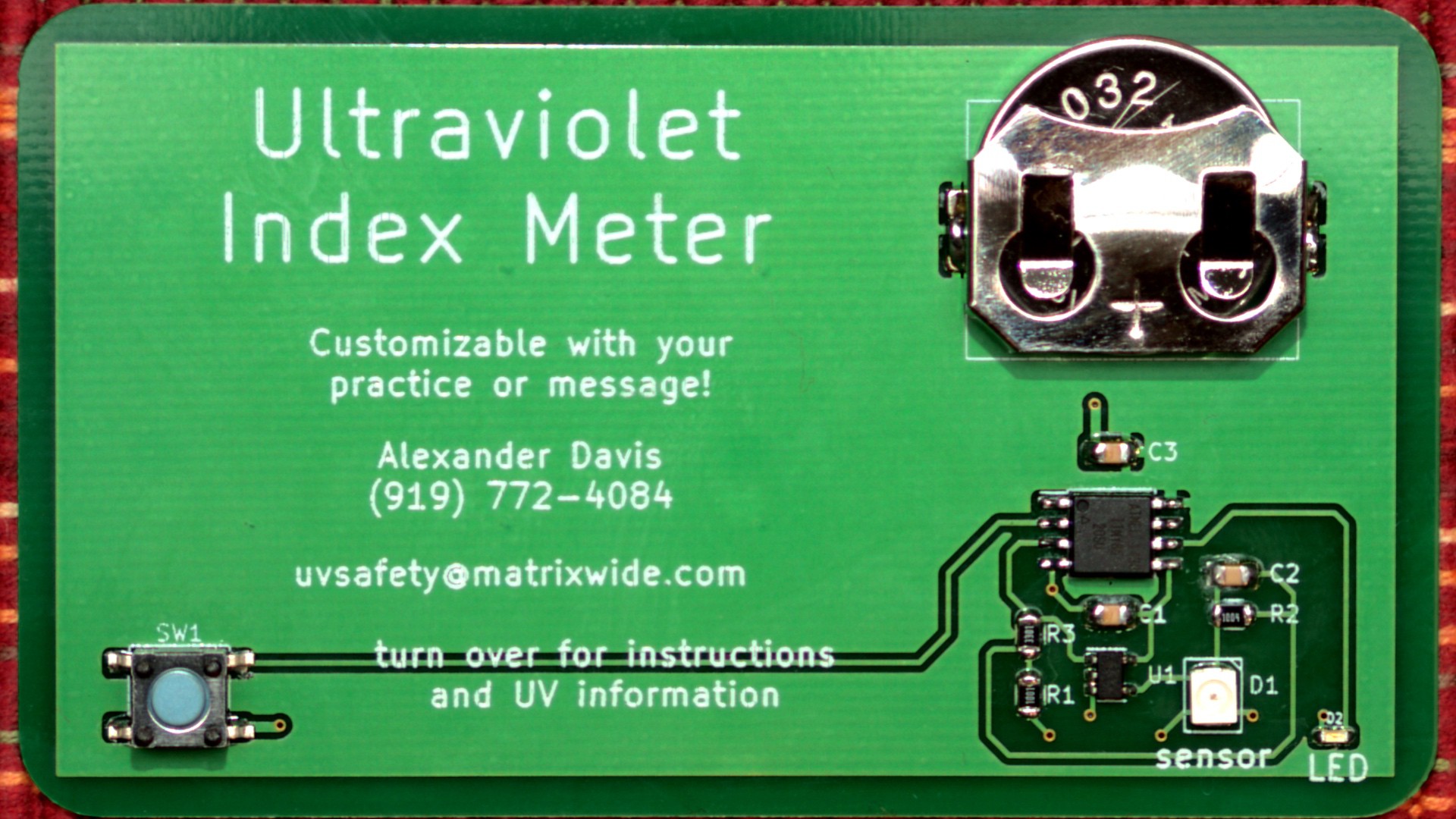
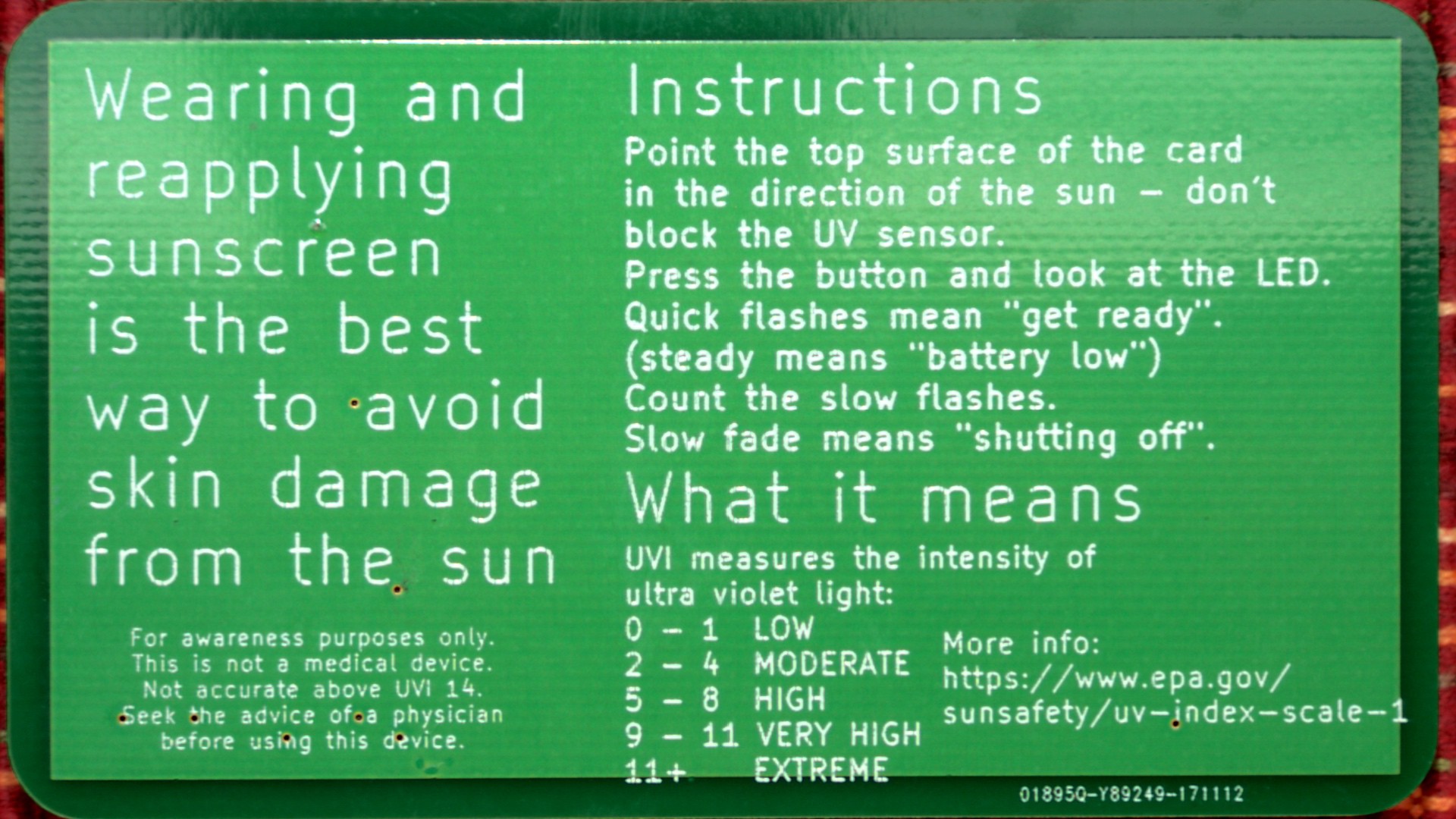
UVI Meter Business Card
An Ultra Violet Light Index (UVI) meter in business card format.