Maave
Maave-
Still alive, new nrf module, USB-C version
05/17/2019 at 15:52 • 0 commentsThis project has been on hold for over a year so I could deal with life stuff. I'm getting back on track.
It's time for a new module. I'm upgrading to the nrf52 series which should fix RAM usage, allow me to use an updated SoftDevice, and possibly use mbed OS 5.
I bought a cheap Chinese nRF52832 module similar to my nrf51822 so that I can hand solder it. If the pinout is reasonably close I'll transplant it onto my existing perfboard prototype.
Planning ahead for production, I found the Fanstel BM832 (nRF52832, 64KB RAM) and the reduced-cost BM832a (nRF52810, 24KB RAM). We'll see if I can keep the RAM under 24KB but it's not a priority. These modules are already FCC certified so I won't have to foot that bill if I ever sell these. The modules are BGA so I'd have to set up a reflow oven.
In other news, I'm attempting a USB-C version! This idea has been on the backburner for a while but there's a flex PCB contest going on right now. Using a flex PCB will allow the controller to reshape for multiple phone sizes - a key feature of this project. The deadline is fast approaching so hopefully I can crank it out and win a prototype.
I've made a new project page for the USB-C version. More updates to come so hit that Follow button.
-
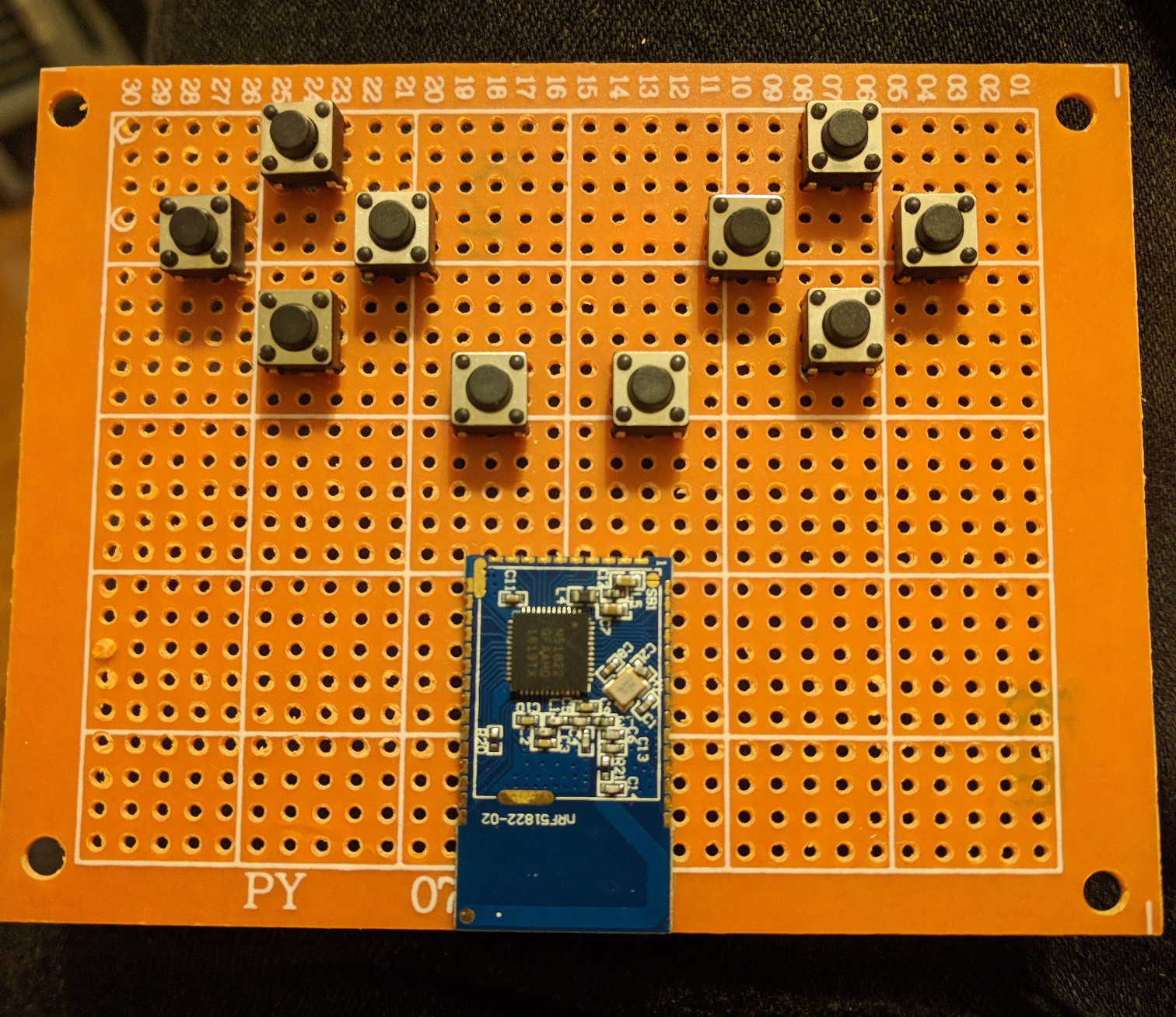
Perfboard prototype with WT51822-S2
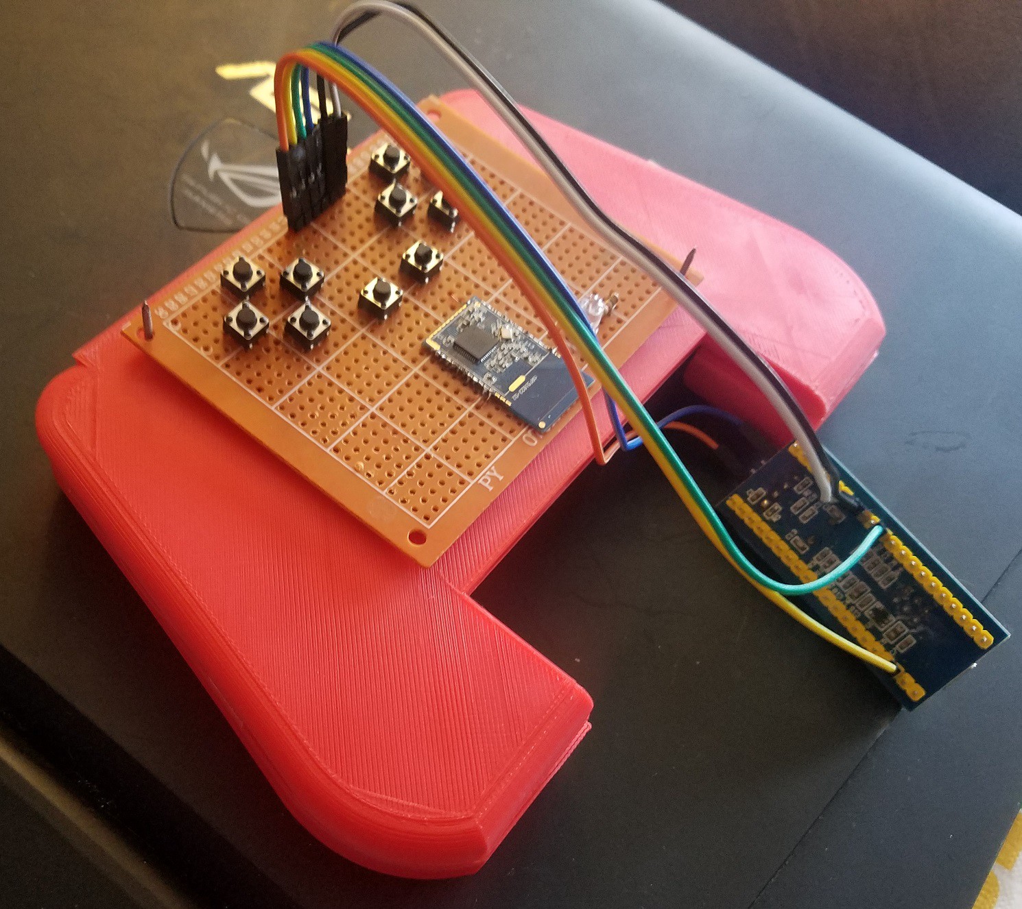
03/19/2018 at 21:06 • 0 commentsHere's the current state of development. The test hardware mostly works! I've been using through-hole components on perfboard and connecting them to the WT51822-S2 with magnet wire. My soldering skills are low but it's getting the job done. Inspiration comes from NE555's beautiful perfboard work.
Here's an early pic with no wiring.
![]()
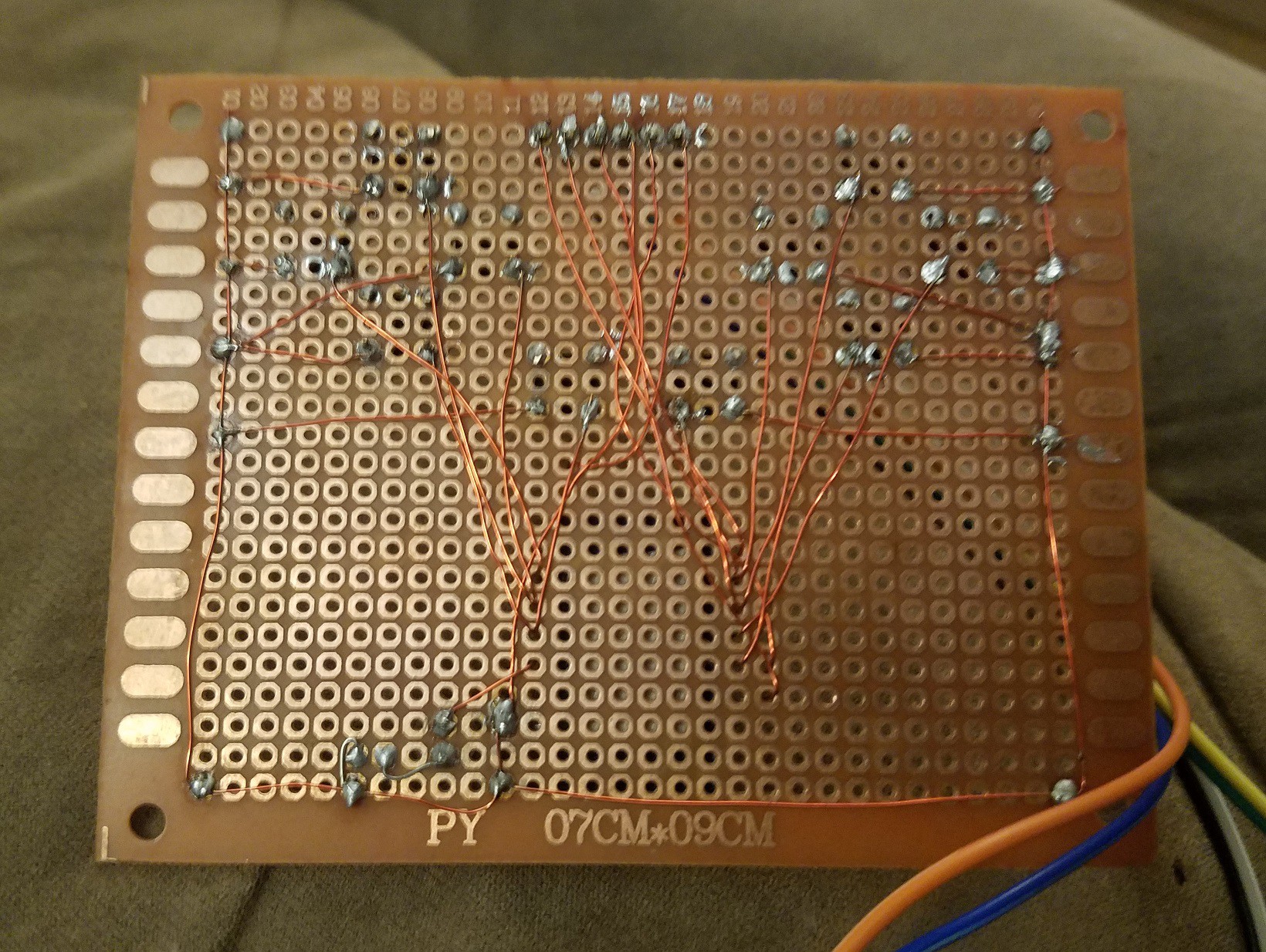
Current version's backside. The ground wire runs around the perimeter so that I can easily wire buttons to ground. Two buttons don't work - I probably didn't strip the enamel well enough for those wires - but all the rest works.
![]()
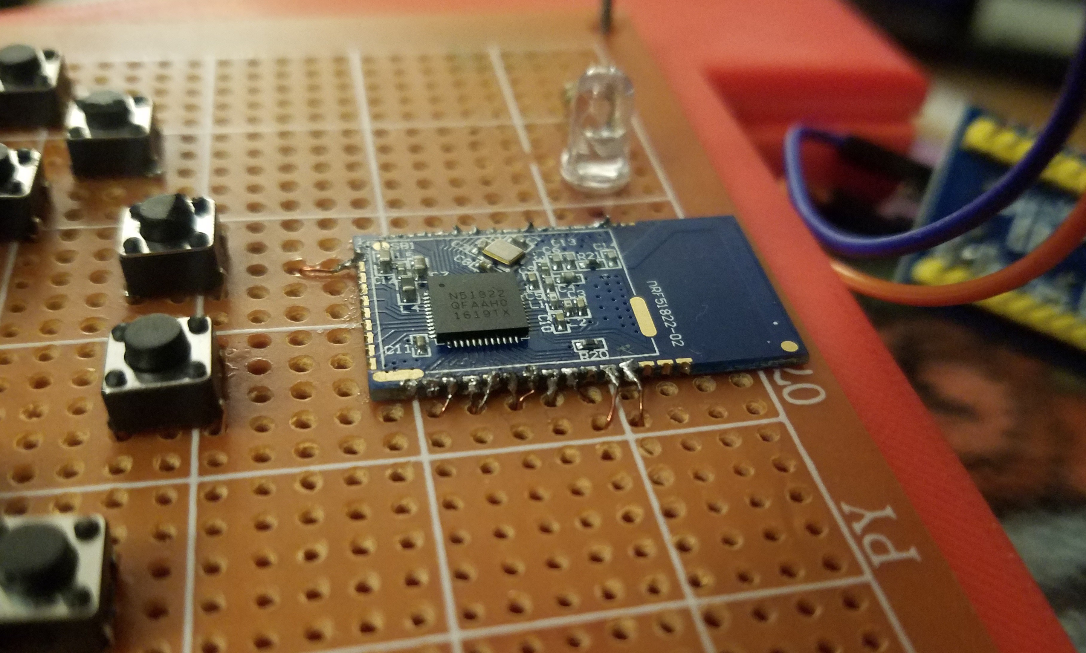
Close up to the module:
![]()
Ugly soldering but functional. The low temp enameled wire is pretty easy to work with (I had some high temp and gave that up very quickly). Flux and tin the contact. Strip and tin the end of the wire with a blob of solder. Solder the wire to the contact. Helping hands would make this easier to solder.
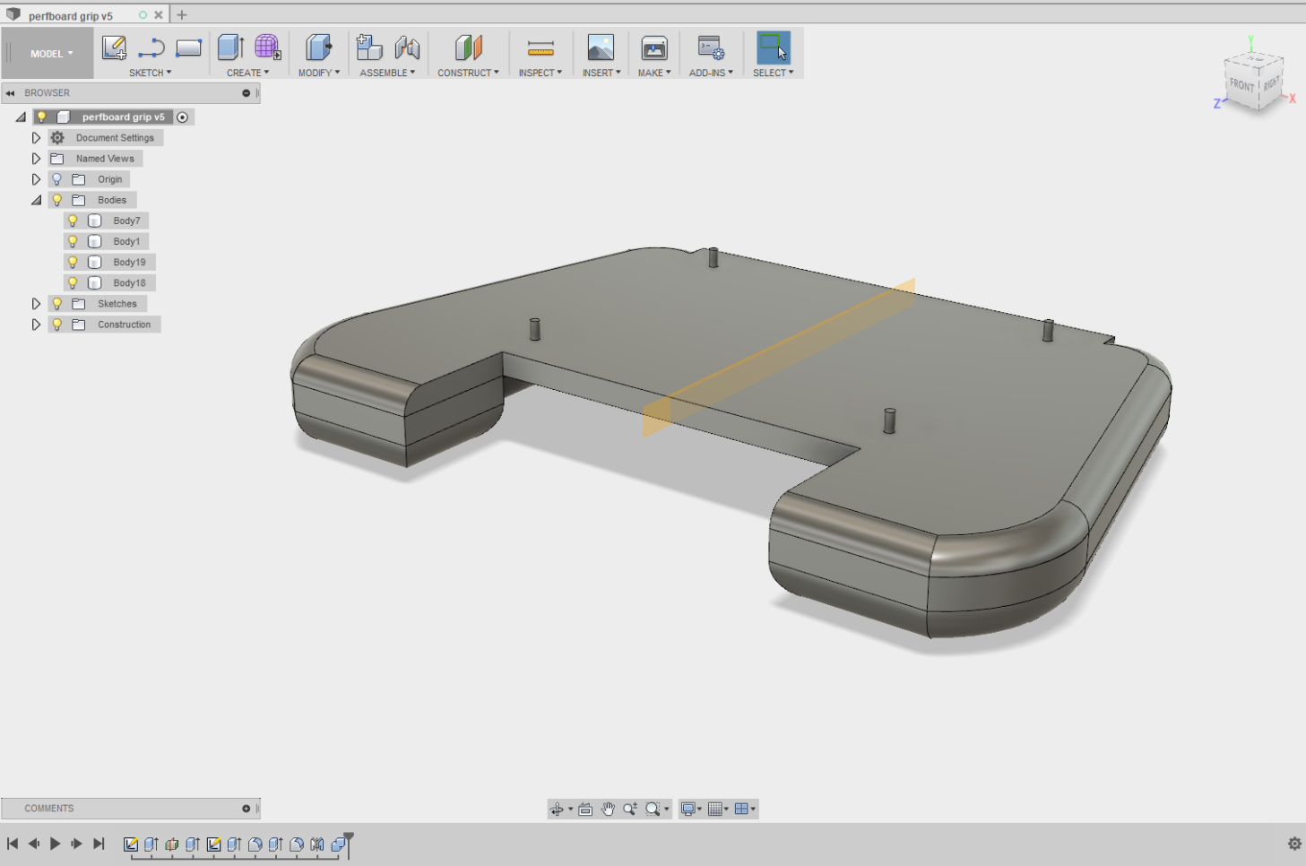
I modeled this grip in Fusion 360 and 3d printed on our CEL Robox.
![]()
Those pegs were meant to hold the perfboard. They broke off in a heartbeat. In their place I tapped some nails through the grip to hold the board. The grip itself isn't really comfortable but it's better than holding the perfboard. Good enough - I'll conserve my effort for other tasks.
![]()
Here you can see the BlackMagic Probe reflashed STM32 that I'm using for development. SWD is used for programming and UART for serial output, both running simultaneously on the same device thanks to BMP firmware.
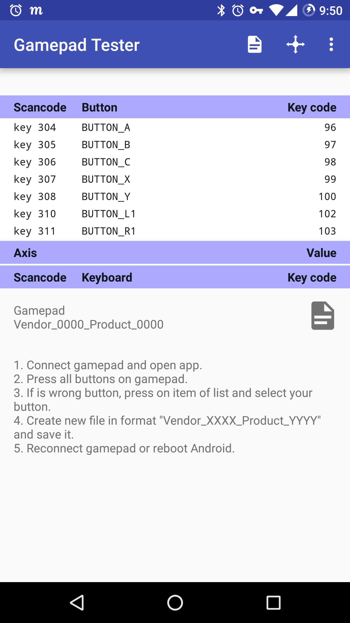
The software sorta works. I'm using Gamepad Tester on Android to verify.
![]()
Using mbed OS I managed to get it to work although there are some bugs and quirks. Fixing these are my main work right now
RAM usage - Mbed + the SoftDevice (Nordic's BLE stack) runs dangerously close to 16k RAM. Newer versions of mbed will throw out-of-memory errors. Build 131 has been working fine. Unfortunately mbed dropped support for SoftDevice S110 which uses 2k less RAM. According to some guide (which I lost, gotta re-find that) I should be able to allocate less RAM to the SoftDevice in the linker as long as I don't use the Central role.
HID Report Descriptor - My HID Report Descriptor isn't working with multiple bytes. The BLE API gives me BLE_ERROR_INVALID_STATE when I try, even when using the working source from Ozan's nrf51822 controller. I have a vague idea what the issue is. Right now I'm using a single byte, with 1 bit per button. This is my main priority since I need to send the d-pad buttons separately from the regular buttons - either as a pair of X/Y axis or as a hat switch.
Windows 10 quirks - Win10 has two issues. First is that the buttons aren't coming through to the gamepad configuration thing. Second is that sometimes the BLE will instantly disconnect after connecting. For now I'm simply ditching Windows as a target. It would be nice for testing but in the end this all intended for Android use. I have no idea what's causing either issue.
That's all for now! More updates later when I have some solid software written.
-
core51822 breadboarding, part 2
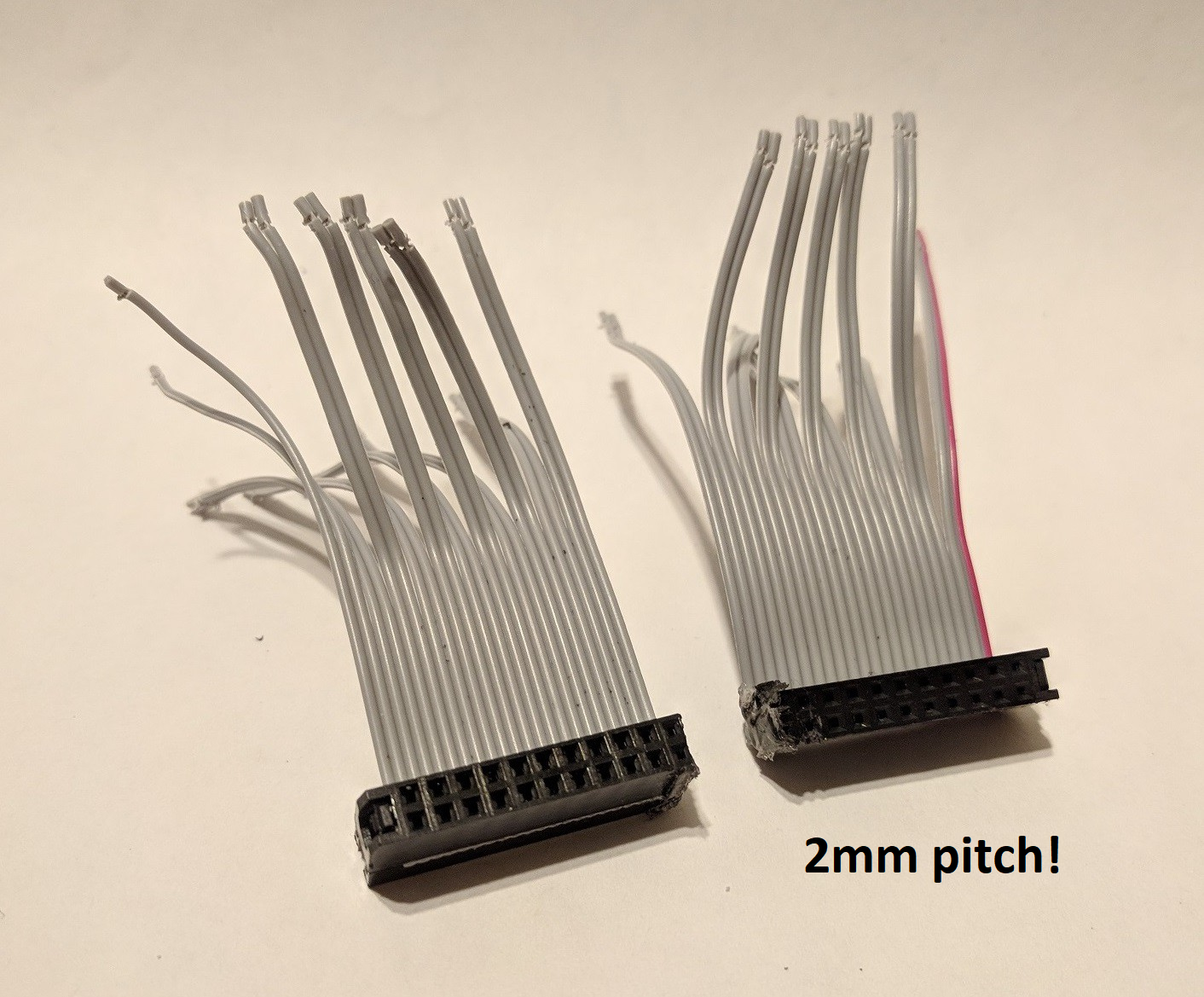
02/05/2018 at 02:24 • 0 commentsMy core51822's headers have been annoying me for a while. I did get a cable to convert these 2mm pitch headers. Unfortunately (or maybe fortunately) I accidentally killed the board! Whoops. I'll keep this log short since the cable isn't relevant to the project anymore - full details are on my blog.
![]()
It's a 44-pin laptop IDE cable. The original connector is 2x24. I sawed it half, mangling only a few of the rows and leaving me with a 2x10 and 2x11 connector. Just right for the core51822's 2x9 headers. The wire is stranded which doesn't play nicely with the breadboard - before using it I soldered a tiny bit of solid wire to the end. I should've bought the longer cable - mine is 2", I should've bought the 8".
Anyway I killed that board so it's on to the next board:
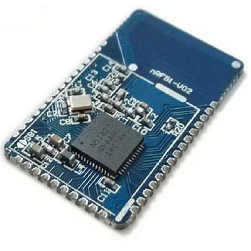
![]()
This one is a little harder to find info on but I believe it's a Wireless-Tag WT51822-S2 module. At the very least Wireless-Tag has the best documentation on the chip. I'll put this module on perfboard and try to get an actual functioning controller.
-
mbed OS for the nrf51822
02/05/2018 at 00:16 • 0 commentsAfter way too much struggling I'm abandoning nrf5 SDK in favor of mbed OS. The Nordic tutorials are sorely lacking. The example code doesn't help since I don't have in-depth knowledge of BLE packet structure. Even if I persist and get it working, the barrier to entry will make it more difficult as a community project: harder to maintain, contribute to, or fork. Meanwhile mbed OS supports the nrf51822 and is MUCH easier.
I was tuned-in thanks to this project, which code-wise is doing exactly what I need.
https://hackaday.io/project/27380-bluetooth-arcade-controller
it's using mbed to simplify everything and a BLE_HID libraryStarting a project:
-sign up for https://os.mbed.com/compiler
-new project
-when it asks for a board, follow the link, find "nrf51822" which is 16k (use the BLE checkbox in the filters on the left)
-click, add
-create a new test project. My template was BLE_Button, you can use whatever you want
-hit Compile. It'll compile (rather quickly!) and provide a flashable .hex file
-download the file, load and run it with gdb
it works!Importing the BLE HID library
-click Import
-Libraries tab
-search "BLE"
-find "BLE_HID", double click to import into projectbam done, start coding. Code samples for the BLE HID can be found on github:
https://github.com/jpbrucker/BLE_HIDSo far I've only used mbed's online IDE and compiler. It's not mind blowing but it's better than Notepad. There is a project gcc4mbed which I can try later with Eclipse, but right now my focus is on getting a prototype.
There are a few versions of mbed OS availble right now. The 16k nrf51822 chips require mbed OS 2 (mbed classic) due to limited RAM. I don't think it will impact the project at all, it seems like the latest OS features are intended for networked/IoT applications. mbed classic has plenty of features and has already simplified my job.
Ozan's arcade controller code is already working but I'm going to try rewriting it from scratch so thata) I learn C++,mbed, and the HID library
b) I can license the code myself (instead of being a derivative of ARM Ltd's Apache-licensed code)
The code is so straight-forward that I can't reasonably re-write it. I'll just make it a derivative work.
Onward to victory!
-
core51822 breadboarding
12/21/2017 at 21:41 • 1 commentUnfortunately the core51822 modules use a 2.00mm (0.787") pitch rather than regular breadboard 0.1" (2.54mm). It's double row (2x9 pin) as well which makes DIY adapters more difficult.
There are a couple solution.
- buy an Waveshare BLE400 breakout board ($9)
- soldering wires to the headers / replacing the headers ($0)
- modding a pre-existing adapter ($?)
- make an adapter on perfboard (sub $2)
- get a PCB made like this or this
- 44-pin (laptop) ATA cable ($1 from China, $6 from US after shipping)
- 2x10 pin 2mm pitch IDC cable ($4)
- 2x20 pin 2mm pitch headers only (10pk $4) and make your own cable
- buy 2.00mm to 0.1" jumper cables ($5-7)
edit: after using it for a few days my 0.1" jumpers have failed. Scratch that method. I've instead swapped some headers with an inch of 24 AWG wire. More attempts to come later.
-
nrf5 SDK setup, compiling/running sample applications
12/21/2017 at 17:41 • 0 commentsHere's how to get applications for the nrf compiling on Windows. Linux and Mac users will require some small changes the home directory (%USERPROFILE% to ~), serial port (COM8 to /dev/ttyACM0), etc. I'm still working on some of these settings - I'll add it to a Github Wiki later for updating and versioning.
There are some quick start guides
http://redbearlab.com/nrf51822-sdk/
http://floe.butterbrot.org/matrix/hacking/nrf/
And read Nordic's actual docs
http://infocenter.nordicsemi.com/topic/com.nordic.infocenter.nrf51/dita/nrf51/nrf51_series.html?cp=3
The section "Application Notes > nAN36 - Creating Bluetooth Low Energy Applications Using nRF51822" is helpful for programming even though it's on an older SDK.
Read the specs for which SoftDevice version you're using. Mine is S130 V2.0
http://infocenter.nordicsemi.com/pdf/S130_SDS_v2.0.pdf
Acquiring / unpacking everything
Software we'll need:
- nrf5 SDK v12 (I may change to v10 or v11 later)
- nrf SoftDevice S130 (I may change to S110 later)
- nrf5x Command Tools (contains mergehex.exe)
- make v3.81
- gcc-arm-none-eabi v4.9
All theNRF downloads:
https://www.nordicsemi.com/eng/Products/Bluetooth-low-energy/nRF51822#DownloadsI'm calling my main directory "nrf" and placing it in my user directory. After unpacking everything it looks like this:
/make-3.81/
/gcc-arm-none-eabi-4_9-2015q3-20150921-win32/
/s130_nrf51_2.0.1_API/
/nRF5_SDK_12.3.0_d7731ad/
/mergehex.exe
/s130_nrf51_2.0.1_softdevice.hex
my nrf makefile location:
/nRF5_SDK_12.3.0_d7731ad/components/toolchain/gcc/Makefile.windowsWhen I edited Makefile.windows I saw this line:
GNU_VERSION := 4.9.3
I assume that all makefiles are written for gcc 4.9.3 so I specifically got that version (4_9-2015q3).
I only needed to change my GNU_INSTALL_ROOT variable. I might change this later to match Eclipse, once that is finally configured.GNU_INSTALL_ROOT := C:/Users/Maave/nrf/gcc-arm-none-eabi-4_9-2015q3-20150921-win32
PROGFILES lines were not needed. I didn't need to make any changes to Makefile.common
Configure makefile to match chip
I went to compile the example programs and found more directories such as "pca10028" etc. There are different types of nRF5* chips and these extra directories are the particular dev boards. The latest SDK should work for this chip, it's just not configured by default. So we make some tweaks.
Finding chip model
My two modules have chips:
- nRF51822-QFAAh0
- nRF51822-QFAAh1
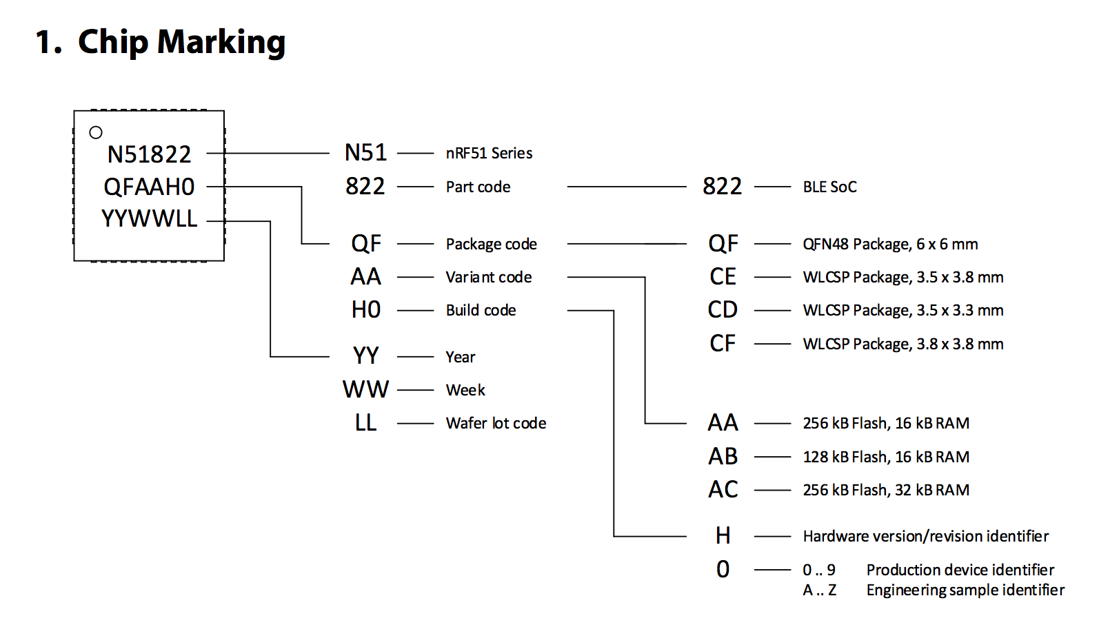
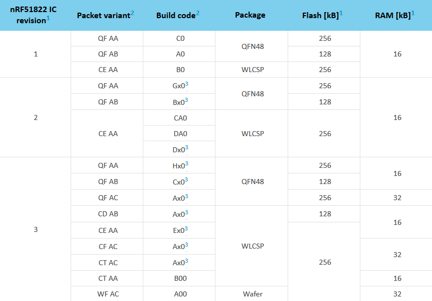
to find your chip details, check the chip marking (source):
![]()
Then compare it to Nordic docs:
![]()
Packet variant and the first two digits in the build code can be read from markings on top of the nRF51 IC.
aka only "h0" and "h1" are actually written on the IC. The last digit is not written.
so now with the chart I know all my chip details
packet variant: qfaa
build code: h00 and h10
package: QFN48
flash: 256kb
ram: 16kb
These specs match the pca10001 development board. The latest SDKs don't have samples for the pca10001 but they do have samples for the similar pca10028 (nrf51422). I still don't know exactly which SDK or SoftDevice is ideal for this project.
https://devzone.nordicsemi.com/question/90024/ic-rev-vs-compatibility-table-vs-sd-vs-sdk/
QFAAH1 is a rev 3 chip. To save yourself a lot of headache I recommend that you use the rev 3 chip, and the latest SDK and SoftDevice. SDK 11 and SoftDevice S132.
https://devzone.nordicsemi.com/question/51402/difference-between-pca10001-pca10028/
PCA10001 uses the nRF51822-QFAA, PCA10028 uses nRF51422-QFAC, Should be the same XTAL and LFCLK
PCA10028 has more RAM (32k instead of 16k in PCA10001), so you need to change the IRAM settings in your project. Flash seems same so IROM values should be same.https://devzone.nordicsemi.com/question/71733/using-pca10001-board-with-nrf51-sdk-on-mac-os-x/
Copy one of board directories, eg pca10028, to pca10001, then go edit the makefile in there to change the board define to BOARD_PCA10001. You may also need to look at the linker script and ensure it matches your board.
The following boards are supported:
Board #define
PCA10001 (part of nRF51822 Evaluation Kit) BOARD_PCA10001Depending on the device on the legacy board, you might need to change the memory layout. For example, all nRF51 examples assume that you are using the 32 kB variant of nRF51, so if you are using a variant with 16 kB RAM, you must decrease the size of IRAM1 by 16 kB (0x4000 in hex) .... For GCC, change the linked *.ld file in the Makefile.
time to copy a pca10028 example. So I go into my examples dir I picked a simple one. Two notes
- pick a simple application like blinky, not the heartrate sensor (I ran out of memory trying to run that)
- our device is a peripheral so check /peripheral or /ble_peripheral
nRF5_SDK_12.3.0_d7731ad\examples\ble_peripheral\experimental_ble_app_blinky\
copy the pca10028 folder and name the new copy pca10001.
edit the makefile:
nRF5_SDK_12.3.0_d7731ad\examples\ble_peripheral\experimental_ble_app_blinky\pca10001\s130\armgcc\Makefilereplace:
xxac with xxaaThese replacements appear optional:
51422 with 51822
10028 with 10001 (this will change features of the board like how many buttons are available)
Linker settings
The Softdevice reserves some amount of RAM and ROM on the chip depending on the features used. The linker decides what memory addresses to use. I'm using S130 SD v2:
http://infocenter.nordicsemi.com/pdf/S130_SDS_v2.0.pdf
Chapter 15 (p51)
SoftDevice memory usageFlash Value
Required by the SoftDevice 104 kB
Required by the MBR 4 kB
APP_CODE_BASE address (absolute value) 0x0001B000RAM
Required by the SoftDevice (in bytes):
0x1288 + Configurable Resources
Minimum: 0x13C8 (5064)APP_RAM_BASE address (minimum required value):
0x20000000 + SoftDevice RAM consumption
Minimum: 0x200013C8in the linker file we adjust the memory values
\nRF5_SDK_12.3.0_d7731ad\examples\ble_peripheral\experimental_ble_app_blinky\pca10001\s130\armgcc\ble_app_hrs_gcc_nrf51.ldhttps://devzone.nordicsemi.com/question/129276/nrf51822_xxaa-sdk12-s130-v201-irom-and-iram-settings/
The IROM number is correct for S130 V2.0.1
The IRAM varies depending on how you configure the SoftDevice, how many services/characteristics you add, etc. For experimental_ble_app_blinky the default IRAM base should be 0x20001fe8 in SDK 12.1, if you add something extra to the default example, you need to increase the number.so depending on the application I'm making I'll have to change the RAM sizes. The pca10028 that I copied has 32kb RAM so I'll have to tweak it. The Windows calculator's programmer mode was handy here
RAM (rwx) : ORIGIN = 0x20001fe8, LENGTH = 0x6018
the RAM value starts at 0x20000000, so the SoftDevice is consuming 0x1fe8. Quick verification:
0x1fe8 -> 8168 (for soft device)
0x6018 -> 24600 (for application)
total: 32768 aka 32 KiBnow I tweak for the nrf51822's 16 KiB RAM
RAM (rwx) : ORIGIN = 0x20001fe8, LENGTH = 0x2018
0x1fe8 -> 8168 (for soft device)
0x2018 -> 8216 (for application)
total: 16384 aka 16 KiBHere's another sample from the S110 softdevice on an nrf51822. S110 uses less RAM. This guy takes advantage of GNU ld's notation to make it much easier to read. I'll use this notation later.
https://devzone.nordicsemi.com/question/75936/nrf52-sdk11-how-to-manage-linker-file/
The linker script defines the available memory of your chip, so it will be different for a 16k or 32k RAM IC, etc. It must be configured depending on the IC version you use and also depends on the SoftDevice you use because some memory is reserved for it.
Here is a linker script I use for my nRF51 (16k RAM, 256k FLASH with SoftDevice S110)FLASH (rx) : ORIGIN = 0x0 + 96K, LENGTH = 256K - 96K
RAM (rwx) : ORIGIN = 0x20000000 + 8K, LENGTH = 16K - 8KOne more example of linker settings
https://devzone.nordicsemi.com/question/59215/nrf51822-flash-programming-problem/
Example .ld file for 256K/32K RAM variants running s110 v.8.0.0:
...
and same for 256K/16K:MEMORY
{
FLASH (rx) : ORIGIN = 0x18000, LENGTH = 0x28000
RAM (rwx) : ORIGIN = 0x20002000, LENGTH = 0x2000
}
Compiling
now that it's all configured it can be compiled
cd nRF5_SDK_12.3.0_d7731ad\examples\ble_peripheral\experimental_ble_app_blinky\pca10001\s130\armgcc\
make-3.81\bin\make.exe -f Makefile
that creates our binaries in _build. If the code utilizes the Softdevice (necessary for Bluetooth) then we merge the hex files. If it doesn't use Softdevice then we can skip this step.
cd %USERPROFILE%\nrf
mergehex.exe --merge s130_nrf51_2.0.1_softdevice.hex .\nRF5_SDK_12.3.0_d7731ad\examples\ble_peripheral\ble_app_beacon\pca10001\s130\armgcc\_build\nrf51822_xxaa.hex --output blink.hex
Flashing
https://github.com/blacksphere/blackmagic/wiki/Useful-GDB-commands
https://devzone.nordicsemi.com/blogs/1149/flashing-and-debugging-nrf5152-with-a-cheap-blackm/
arm-none-eabi-gdb.exe
(gdb) target extended-remote COM8
(gdb) monitor swdp_scan
(gdb) attach 1
(gdb) cd whatever/directory/_build
(gdb) load blink.hex
(gdb) run
My LED blinks!
-
STM32 Black Magic Probe flashing
12/07/2017 at 18:28 • 1 commentI'll be using Black Magic Probe to program/debug my "core51822" nrf51822 modules. Cheap STM32 boards can be flashed with the BMP firmware. (Note: Maple Mini board didn't work, stick to STM32F103C8T6 boards). HaD gave a brief summary about BMPs:
https://hackaday.com/2016/12/02/black-magic-probe-the-best-arm-jtag-debugger/
Quick cost comparison of dev options:
-STM32F103C8T6 ($3) + FTDI serial adapter clone ($2) + core51822 or similar modules ($6) = $11
-NRF51 DK ($34)
-Segger J-Link EDU ($60 not incl shipping) + core51822 or similar modules ($6) = $66+
The STM32 parts were sourced from China. It'll be $15-$20 if shipped from the US. I already had the serial adapter from the Arduino work so this was cheapest route bay far. Also I swear the NRF51 DK was $100 when I first checked and that's why I went the STM32/core51822 route. Now it's only $34. This is a very tempting option since it's officially supported and easier to set up. The DK has SWD pins so it can flash other modules as well.
On to the Black Magic Probe flashing. All of the guides were for Linux so I used my VM, Thinking about it now I probably could have compiled using the Windows build of gcc. Oops, too late. If other people get into this I'll find/write a build script so that people can download the prebuilt firmware.
The two guides I mostly followed:
https://medium.com/@paramaggarwal/converting-an-stm32f103-board-to-a-black-magic-probe-c013cf2cc38c
https://gojimmypi.blogspot.com/2017/07/BluePill-STM32F103-to-BlackMagic-Probe.htmin terminal:
mkdir mbp
cd mbp
wget https://raw.githubusercontent.com/jsnyder/stm32loader/master/stm32loader.py
chmod 774 stm32loader.py
sudo apt install python-pip
pip install pyserial --assume-yes
sudo apt install arm-none-eabi-gdb
Wiring pic from the Medium guide. If you check STM32 board pinouts you'll see that A9 and A10 are TX and RX respectively.
Wire up the boards according to the guide, plug in the FTDI USB, pass through the FTDI in VirtualBox to the VM. It connects as /dev/ttyUSB0 as shown in dmesg:
dmesg | grep tty
sudo ./stm32loader.py -p /dev/ttyUSB0
Test build BMP firmware:
sudo apt-get install gcc-arm-none-eabi --assume-yes
sudo apt-get install dfu-util --assume-yes
git clone https://github.com/blacksphere/blackmagic.git
cd blackmagic
make
If that completes without errors then build the STM32 versioncd src make clean && make PROBE_HOST=stlink
That creates blackmagic_dfu.bin and blackmagic.bin. Now the firmware is built and can be flashed to the STM32. Either hit reset on the STM32 or unplug/replug. Then flash:sudo ./stm32loader.py -p /dev/ttyUSB0 -V -e -w -v ./blackmagic/src/blackmagic_dfu.binUnplug it all. We don't need the USB to serial anymore. Reset the STM32's boot1 jumper to 0. Plug it through USB. The BMP updater firmware doesn't work with Win10 so I have to install the libusbK drivers using Zadig as mentioned here:
https://docs.particle.io/faq/particle-tools/installing-dfu-util/core/#windows-32-bitHave the STM32 plugged in, start Zadig, select Black Magic (Upgrade) in the dropdown, use the arrows to select libusbK, install driver. VirtualBox still didn't pass through, and I'm being dumb and lazy, so I just used the dfu-util Windows build and transferred blackmagic.bin to Windows. Use dfu-util v0.9. Some other guide I had been following used v0.6 but that caused issue for me.
http://dfu-util.sourceforge.net/releases/dfu-util-0.9-win64.zip
Check the device ID with:
dfu-util.exe -lwhich returned "Found DFU: [1d50:6017]" etc, I guess that's it. Time to flash:
dfu-util.exe -d 1d50:6017 -s 0x08002000:leave -D blackmagic.binMine succeeded, the Black Magic device shows in Windows. If you get errors, check gojimmypi's account of fiddling with the memory.
I gave it a quick test in gdb as well. I was able to start gdb and set the target.
https://github.com/blacksphere/blackmagic/wiki/Useful-GDB-commands -
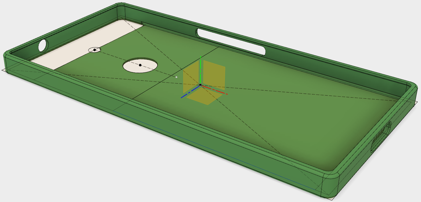
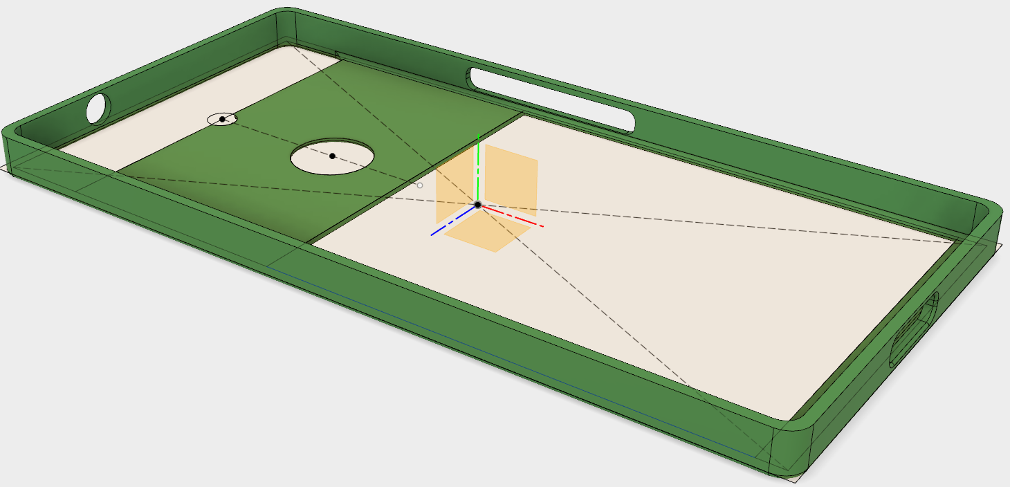
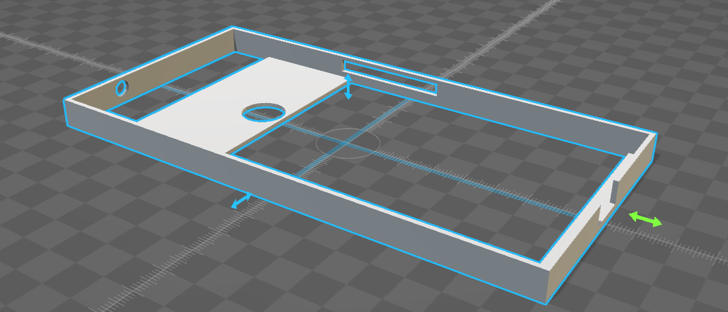
Phone case modeling
12/04/2017 at 20:48 • 0 commentsPhone case design time. I'll be 3d printing this, first in ABS, then in TPU, and eventually using it as a daily driver. I chose Fusion 360 this time to make it easier to edit the model. This is sooo much better than Sketchup, doesn't royally screw the model when I apply fillets, and it allows me to suppress feature later in development.
Here's the best tutorial I found. The only thing he forgot to mention is the camera controls (middle mouse to pan, shift+middle to orbit).
https://www.youtube.com/watch?v=A5bc9c3S12g&list=PL40d7srwyc_Ow4aaOGXlP2idPGwD7ruKgHere's a supplementary tutorial following the designer's natural workflow
https://www.youtube.com/watch?v=E0bhdr84FNUScreenshot of the case:
The "test" version with top lip removed so that I can print in hard ABS and a filament-saving space:
This will be printed on a CEL Robox using ABS. If the test print goes well then I'll print in TPU. I group bought a printer with friends but it's currently down. I'm waiting for my friend to calibrate the bed after installing a new sticky print bed. We'll still have to mod the feed system to work with TPU.
-
Prior attempt
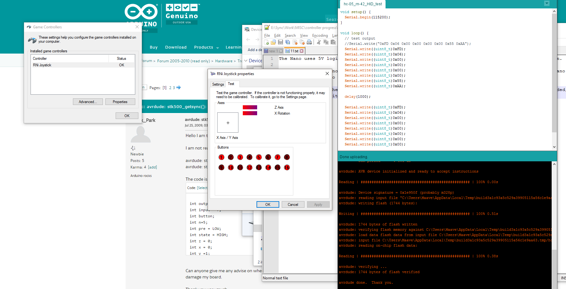
12/04/2017 at 14:39 • 0 commentsI documented my prior attempt but the results weren't great. Here's the summary for historic purposes. This is my first real electronics project so I wanted it easy. I used an Arduino with an HC-05 Bluetooth module reflashed with RN-42 firmware, and Sketchup for the phone case modeling. The HC-05 worked but I don't think that reflashing the firmware is appropriate for a community project. Sketchup was entirely inadequate.
I ordered parts, breadboard components, and soldering iron. I learned microcontroller basics on the Arduino - blinking LEDs, voltage dividers, button input, debouncing buttons, pull up / pull down, bitpacking. The Arduino was great for learning that. I re-learned soldering which I haven't done in years, and breadboarding. Pro tip, don't buy bottom of the barrel jumpers, half of mine are dead and it caused endless frustration.
EEVblog how to solder:
https://www.youtube.com/playlist?list=PL2862BF3631A5C1AAConcepts and mindset of soldering:
https://www.youtube.com/watch?v=vIT4ra6Mo0sI had the parts ready when mitxela's guide appeared on HaD so my HC-05 attempt was based off this guide:
https://mitxela.com/projects/bluetooth_hid_gamepadI got the controller to show as an HID gamepad in Windows. This is where I stopped with the Arduino/HC-05 and ordered nrf51822 gear. It can definitely work, I just don't think it's ideal.
![]()
Here's the phone case I started for my Nexus 6P. My friends and I had already been using Sketchup for other projects however it turned out to be a poor choice for small models - I had issues with keeping faces flat and with Sketchup combining nearby lines.
![]()
My new attempt is using the nrf51822 BLE SoC and Fusion 360. I got nrf51822 compiling and flashing working but no code of my own yet. I've made great progress with Fusion 360, parametric modeling rocks. More updates to come.
Bluetooth Gamepad Phone Case
A bluetooth gamepad integrated into a phone case.
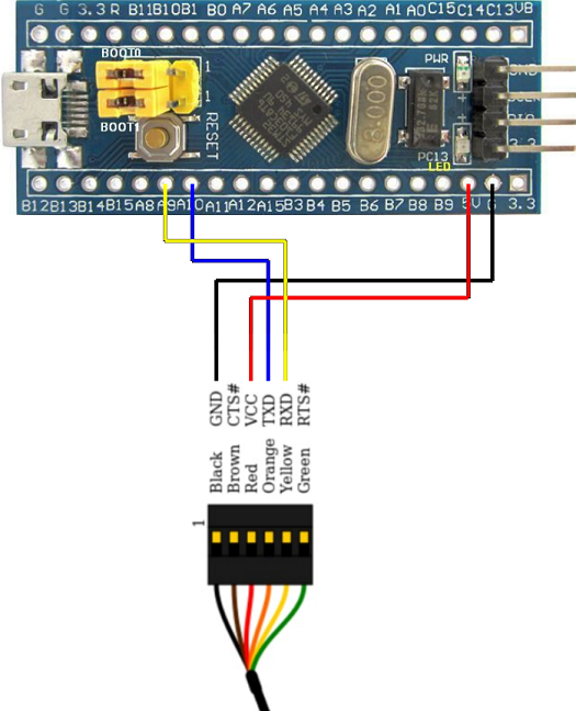 Wiring pic from the Medium guide. If you check STM32 board pinouts you'll see that A9 and A10 are TX and RX respectively.